Table of Contents
Advertisement
Quick Links
SERVICE MANUAL
Ver. 1.0 2008.07
CD player section
System
Compact disc digital audio system
Laser diode properties
Emission duration: Continuous
Laser output: Less than 44.6 μW
(This output is the value measurement at a distance of
200mm from the objective lens surface on the
Optical Pick-up Block with 7mm aperture.)
Spindle speed
200 r/min (rpm) to 500 r/min (rpm) (CLV)
Number of channels
2
Frequency response
20 - 20 000 Hz +1/–2 dB
Wow and fl utter
Below measurable limit
Radio section
Frequency range
FM: 87.5 - 108 MHz
AM: 531 - 1 611 kHz (9 kHz step)
530 - 1 610 kHz (10 kHz step)
Antennas
FM: Telescopic antenna
AM: Built-in ferrite bar antenna
Sony Corporation
9-889-220-01
2008G04-1
Audio&Video Business Group
©
2008.07
Published by Sony Techno Create Corporation
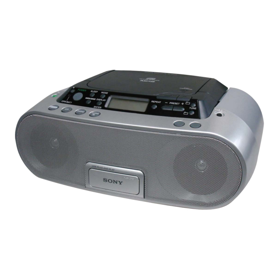
ZS-PS20CP
Model Name Using Similar Mechanism
CD
CD Mechanism Type
Section
Optical Pick-up Name
SPECIFICATIONS
USB section
Supported bit rate
MP3 (MPEG 1 Audio Layer-3):
32 - 320 kbps, VBR
WMA:
16-320Kbps,VBR
Sampling frequencies
MP3 (MPEG 1 Audio Layer-3):
32/44.1/48 kHz
WMA:
32/44.1/48kHz
(USB) port
USB-A (Full Speed)
General
Speaker
Full range: 8 cm (3
Input
(USB) port: Type A, maximum
current 500 mA
AUDIO IN jack (stereo minijack)
Outputs
Headphones jack (stereo minijack)
For 16 - 68 Ω impedance headphones
Power output
1.7 W + 1.7 W (at 4 Ω, 10% harmonic distortion)
PERSONAL AUDIO SYSTEM
AEP Model
UK Model
Australian Model
Singapore Model
Korea Model
Thai Model
ZS-S2iP
KSM-213CDP
KSS-213C
inches) dia., 4 Ω, cone type (2)
1/4
– Continued on next page –
Advertisement
Table of Contents

Related Manuals for Sony ZS-PS20CP


Summary of Contents for Sony ZS-PS20CP
- Page 1 1.7 W + 1.7 W (at 4 Ω, 10% harmonic distortion) AM: Built-in ferrite bar antenna – Continued on next page – PERSONAL AUDIO SYSTEM Sony Corporation 9-889-220-01 2008G04-1 Audio&Video Business Group © 2008.07 Published by Sony Techno Create Corporation...
- Page 2 COMPONENTS IDENTIFIED BY MARK 0 OR DOTTED LINE WITH MARK 0 ON THE SCHEMATIC DIAGRAMS AND IN THE PARTS LIST ARE CRITICAL TO SAFE OPERATION. REPLACE THESE COMPONENTS WITH SONY PARTS WHOSE PART NUMBERS APPEAR AS SHOWN IN THIS MANUAL OR IN SUPPLEMENTS PUBLISHED BY SONY.
- Page 3 ZS-PS20CP UNLEADED SOLDER CAUTION Boards requiring use of unleaded solder are printed with the lead- Use of controls or adjustments or performance of procedures free mark (LF) indicating the solder contains no lead. other than those specifi ed herein may result in hazardous radia- tion exposure.
-
Page 4: Table Of Contents
ZS-PS20CP TABLE OF CONTENTS SERVICING NOTES ..........GENERAL Basic Operations ............. Other Operations ............. DISASSEMBLY 3-1. Cabinet (Rear) Assy ............3-2. Cabinet (Front) Assy, Cabinet (Upper) Assy ....3-3. Main Board ..............10 3-4. CD Block Assy ..............10 3-5. Optical Pick-up, CD Board ..........11 3-6. -
Page 5: Servicing Notes
ZS-PS20CP SECTION 1 SERVICING NOTES LASER DIODE AND FOCUS SEARCH OPERATION CHUCK PLATE JIG ON REPAIRING CHECK On repairing CD section, playing a disc without the lid (CD), use 1. Turn ON the [OPERATE] button and press [CD] button to CD Chuck Plate Jig. -
Page 6: General
ZS-PS20CP SECTION 2 GENERAL This section is extracted from instruction manual. Basic Operations Listening to music of a USB device You can listen to music stored on an optional USB device (digital music player or USB storage media). this unit. -
Page 7: Other Operations
Press DISPLAY/ENTER on the unit while playing an the program. You can use the following Sony USB devices on this unit. Repeat to program other tracks in the order that you Other USB devices are not playable on this unit. -
Page 8: Disassembly
ZS-PS20CP SECTION 3 DISASSEMBLY • This set can be disassembled in the order shown below. 3-1. CABINET (REAR) ASSY (Page 9) 3-2. CABINET (FRONT) ASSY, 3-10. POWER BOARD CABINET (UPPER) ASSY (Page 13) (Page 9) 3-3. MAIN BOARD 3-8. USB TRAY ASSY 3-9. -
Page 9: Cabinet (Rear) Assy
ZS-PS20CP Note: Follow the disassembly procedure in the numerical order given. 3-1. CABINET (REAR) ASSY handle telescopic antenna cabinet (rear) assy CN906 (3P) screw ((+) BV tapping (B2.6)) two screws ((+) BV tapping (B2.6)) CN1 (2P) screw ((+) BV tapping (B2.6)) three screws ((+) BV tapping (B2.6)) -
Page 10: Main Board
ZS-PS20CP 3-3. MAIN BOARD HEADPHONE board CN307 (4P) cabinet (upper) section AUDIO IN board CN805 (2P) holder (jack) CN301 (3P) wire (flat type)(20 core) (CN803) wire (flat type)(20 core) connector (CN804) (S801) MAIN board two screws ((+) BV tapping (B2.6)) two screws ((+) BV tapping (B2.6)) -
Page 11: Optical Pick-Up, Cd Board
ZS-PS20CP 3-5. OPTICAL PICK-UP, CD BOARD CD cover two vibration rubbers (RED) optical pick-up two vibration rubbers (GREEN) Remove the four solders. wire (flat type) (16 core) (CN701) CD board screw (+BVTT 2 × 6) 3-6. LCD BOARD four screws ((+) BV tapping (B2.6)) -
Page 12: Cd Lid
ZS-PS20CP 3-7. CD LID CD lid cabinet (upper) section CD spring damper screw ((+) BV tapping (B2.6)) 3-8. USB TRAY ASSY cabinet (front) assy CN1006 (2P) wire (flat type)(6 core) (CN1004) two screws ((+) BV tapping (B2.6)) USB tray assy two screws ((+) BV tapping (B2.6)) -
Page 13: Key (Vol) Board, Key (Func) Board
ZS-PS20CP 3-9. KEY (VOL) BOARD, KEY (FUNC) BOARD CN401 (2P) cabinet (front) assy KEY (FUNC) board button (function) screw ((+) BV tapping (B2.6)) two screws ((+) BV tapping (B2.6)) KEY (VOL) board two hold boards screw ((+) BV tapping (B2.6)) -
Page 14: Electrical Adjustments
ZS-PS20CP SECTION 4 ELECTRICAL ADJUSTMENTS TUNER SECTION 0 dB = 1 μV AM IF ADJUSTMENT Adjust for a maximum reading on level meter. • AM Section Setting: RADIO BAND•AUTO PRESET button: AM 450 kHz AM RF signal generator AM FREQUENCY COVERAGE ADJUSTMENT... - Page 15 ZS-PS20CP Adjustment Location: L3: AM FREQUENCY COVERAGE L2: FM FREQUENCY COVERAGE ADJUSTMENT ADJUSTMENT CT1: FM TRACKING ADJUSTMENT ANT1: AM TRACKING ADJUSTMENT – MAIN BOARD (Component Side) – CT3: AM TRACKING ADJUSTMENT L6: FM IF ADJUSTMENT L1: FM TRACKING ADJUSTMENT T1: AM IF ADJUSTMENT...
-
Page 16: Cd Section
ZS-PS20CP CD SECTION CD section adjustments are done automatically in this set. In case of operation check, confi rm that focus bias. FOCUS BIAS CHECK 1. Connect the oscilloscope between IC701 pin 2 and pin qa (or TP (RF OUT) and TP (VC)). -
Page 17: Diagrams
ZS-PS20CP SECTION 5 DIAGRAMS 5-1. BLOCK DIAGRAM – CD Section – RF OUT LCHO A IN DIGITAL SYNCHRONIZATION MAIN FILTER DETECTION SECTION C IN & EFM DEMODULATION (Page 18) 1-bit DAC RCHO B IN D IN SYSTEM SERVO PROCESSOR, DIGITAL SIGNAL PROCESSOR... -
Page 18: Block Diagram -Main Section
ZS-PS20CP 5-2. BLOCK DIAGRAM – MAIN Section – INPUT SELECT ELECTRONIC VOLUME IC302 IN L3 IN R3 R-CH SECTION R-CH (Page 17) POWER AMP IC303 R-CH J321 J322 OUT1 L R-CH AUDIO IN IN L1 OUT2 R 18 R-CH IN R1... - Page 19 ZS-PS20CP THIS NOTE IS COMMON FOR PRINTED WIRING BOARDS AND SCHEMATIC DIAGRAMS. • Circuit Boards Location (In addition to this, the necessary note is printed in each block.) For Printed Wiring Boards. For Schematic Diagrams. POWER board Note: Note: LCD board CD board •...
-
Page 20: Printed Wiring Board -Cd Section (1/2)
ZS-PS20CP 5-3. PRINTED WIRING BOARD – CD Section (1/2) – • See page 19 for Circuit Boards Location. • : Uses unleaded solder. CD BOARD (SIDE A) C776 C778 C505 R761 C503 C766 R501 R510 R509 C792 R508 R507 R789... -
Page 21: Printed Wiring Board -Cd Section (2/2)
ZS-PS20CP 5-4. PRINTED WIRING BOARD – CD Section (2/2) – • See page 19 for Circuit Boards Location. • : Uses unleaded solder. (Page 23) MAIN BORD CN801 • Semiconductor CD BOARD (SIDE B) Location Ref. No. Location D701 E-10... -
Page 22: Schematic Diagram -Cd Section
ZS-PS20CP 5-5. SCHEMATIC DIAGRAM – CD Section – • See page 19 for waveforms. • See page 32 for IC Block Diagrams. • See page 36 for IC Pin Function Description of IC702. CN702 R518 C519 R521 TP701 TP702 R514... -
Page 23: Printed Wiring Board -Main Section
ZS-PS20CP 5-6. PRINTED WIRING BOARD – MAIN Section – • See page 19 for Circuit Boards Location. • : Uses unleaded solder. (Page 30) (Page 27) (Page 30) (Page 27) (Page 21) POWER HEADPHONE POWER USB RELAY (1) BOARD BOARD... -
Page 24: Schematic Diagram -Main Section (1/3)
ZS-PS20CP 5-7. SCHEMATIC DIAGRAM – MAIN Section (1/3) – • See page 19 for waveform. • See page 33 for IC Block Diagram. IC B/D (VT) ANT1 ANT2 TP103 R170 C163 TP203 R270 C263 (Page 26) (Page 31) (Page 25) -
Page 25: Schematic Diagram -Main Section (2/3)
ZS-PS20CP 5-8. SCHEMATIC DIAGRAM – MAIN Section (2/3) – • See page 19 for waveforms. • See page 34 for IC Block Diagram. • See page 37 for IC Pin Function Description of IC801. (Page 24) (Page 26) L803 TP811... -
Page 26: Schematic Diagram -Main Section (3/3)
ZS-PS20CP 5-9. SCHEMATIC DIAGRAM – MAIN Section (3/3) – • See page 34, 35 for IC Block Diagrams. R251 R151 CN301 CN302 FB102 R177 TP161 TP102 FB101 FB301 J322 FB202 C164 TP202 FB201 R161 R261 IC B/D TP261 FB302 C264... -
Page 27: Printed Wiring Boards -Audio In, Hp, Usb Section
ZS-PS20CP 5-10. PRINTED WIRING BOARDS – AUDIO IN, HP, USB Section – • See page 19 for Circuit Boards Location. • : Uses unleaded solder. J321 J322 (Page 21) (Page 23) AUDIO IN MAIN BOARD BOARD CN703 CN904 USB RELAY (1) -
Page 28: Printed Wiring Boards -Key, Lcd Section
ZS-PS20CP 5-11. PRINTED WIRING BOARDS – KEY, LCD Section – • See page 19 for Circuit Boards Location. • : Uses unleaded solder. (Page 23) (Page 23) LCD BOARD MAIN MAIN BOARD BOARD CN804 CN803 IC401 S407 S406 R422 R421... -
Page 29: Schematic Diagram -Key, Lcd Section
ZS-PS20CP 5-12. SCHEMATIC DIAGRAM – KEY, LCD Section – LCD401 CN406 (Page 25) (Page 25) R435 R401 R403 R406 R407 R408 R409 R410 R402 R404 S401 S402 S403 S404 S405 D401 R405 CN405 R411 R412 R413 R414 R415 R416 R417 R418 R419... -
Page 30: Printed Wiring Boards -Power Section
ZS-PS20CP 5-13. PRINTED WIRING BOARDS – POWER Section – • See page 19 for Circuit Boards Location. • : Uses unleaded solder. POWER BOARD BATTERY (1) BOARD T901 FH901 FH902 F902 CN907 C907 1-876-996- (11) C901 D901 CN903 D904 C908... -
Page 31: Schematic Diagram -Power Section
ZS-PS20CP 5-14. SCHEMATIC DIAGRAM – POWER Section – CN1004 CN1003 (Page 22) CN1005 CN1006 (Page 26) CN909 FH904 F901 CN902 CN903 FH903 CN907 J901 T901 F902 FH902 FH901 CN905 (Page 24) CN901 R908 R910 C908 (Page 26) ZS-PS20CP... - Page 32 ZS-PS20CP • IC Block Diagrams IC703 LA6548NHL-TE-L-E (CD Board) VCC1 1 VCC2 IC701 LC786924T-US-H (CD Board) MUTE CONTROL MUTE VREF VIN1 3 VIN4 VG1 4 VO1+ 5 VO4+ CLOCK EFMIN 1 LRCY VO1– 6 VO4– GENERATOR PCM Output Control RF OUT 2...
- Page 33 ZS-PS20CP IC1 LV23003VA (MAIN Board (1/3)) 36 FM RF-IN AM RF-IN 35 GND2 34 FM RF-OUT 33 VCC2 FM MIX-OUT 32 FM OSC GND1 AM MIX-OUT 31 AM OSC VCC1 30 BO2 29 BO1 BUFFER LOW-PASS 28 LP-OUT FILTER 27 LP-IN...
- Page 34 ZS-PS20CP IC802 S-24CS02AFT-TB-G (MAIN Board (2/3)) START/STOP DETECT CIRCUIT HIGH VOLTAGE SERIAL CLOCK GENERATOR CONTROL CIRCUIT LOAD DATA DEVICE COMP REGISTER ADDRESS COMPARATOR LOAD EEPROM ADDRESS COUNTER Y DECODER SELECTOR DATA OUTPUT/ ACK OUTPUT/ CONTROL CIRCUIAT DOUT IC302 BD3499FV-E2 (MAIN Board (3/3))
- Page 35 ZS-PS20CP IC303 UTC8227 S (MAIN Board (3/3)) VCC2 VCC1 CH-2 L-OUT R-OUT – L-BS R-BS P.GND P.GND POWER GND RIPPLE CH-1 L-NF – R-NF L-IN R-IN IC901 PQ1C21H2ZPH (MAIN Board (3/3)) CONSTANT VOLTAGE CIRCUIT ERROR AMP COMPARATOR OVER HEAT DETECT...
- Page 36 ZS-PS20CP • IC Pin Function Description CD BOARD IC702 LC87F1HC4AU-SQFP-E (USB I/F) Pin No. Pin Name Description P73/INT3 — Not used (Open) Reset signal input XT1/AN10 — Not used (Connected to ground) XT2/AN11 — Not used (Open) VSS1 — Ground...
- Page 37 ZS-PS20CP MAIN BOARD (2/3) IC801 LC87F7DC8AU-QIP-E (SYSTEM CONTROL) Pin No. Pin Name Description — Not used (Open) M-MUTE Motor driver mute signal output O-CD DO CD DSP serial data output I-CD DI CD DSP serial data input O-CD CLK CD DSP serial transfer clock signal output...
- Page 38 ZS-PS20CP Pin No. Pin Name Description I-CA CHECK AC IN check signal input VSS3 — Ground VDD3 — Power supply (+3.3 V) USB-TXD USB I/F command serial data output USB-RXD USB I/F command serial data input O-CD RES CD DSP reset signal output...
-
Page 39: Exploded Views
ZS-PS20CP SECTION 6 EXPLODED VIEWS Note: • -XX and -X mean standardized parts, so • Color Indication of Appearance Parts Ex- The components identifi ed by mark 0 they may have some difference from the ample: or dotted line with mark 0 are critical for original one. -
Page 40: Front Cabinet Section
ZS-PS20CP 6-2. FRONT CABINET SECTION upper cabinet section SP101 not supplied USB tray assy section not supplied (USB RELAY (1) board) not supplied SP201 Ref. No. Part No. Description Remark Ref. No. Part No. Description Remark 3-254-140-01 SCREW (B2.6), (+) BV TAPPING... -
Page 41: Upper Cabinet Section (1)
ZS-PS20CP 6-3. UPPER CABINET SECTION (1) upper cabinet section (2) S801 Ref. No. Part No. Description Remark Ref. No. Part No. Description Remark 2-654-053-91 LID, CD 3-252-827-01 SCREW (B2.6), (+) BV TAPPING 1-452-899-11 MAGNET A-1552-840-A MAIN BOARD, COMPLETE (EXCEPT AUS,KR) -
Page 42: Upper Cabinet Section (2)
ZS-PS20CP 6-4. UPPER CABINET SECTION (2) not supplied not supplied not supplied 167 168 LCD401 IC401 not supplied S701 not supplied Ref. No. Part No. Description Remark Ref. No. Part No. Description Remark 3-923-736-01 COVER, CD 2-673-399-01 SHEET (IR), ADHESIVE... -
Page 43: Usb Tray Assy Section
ZS-PS20CP 6-5. USB TRAY ASSY SECTION not supplied not supplied not supplied Ref. No. Part No. Description Remark Ref. No. Part No. Description Remark 3-252-828-01 SCREW (B2.6), (+) PWH TAPPING 1-692-960-11 SWITCH, PUSH (1 KEY) 3-252-827-01 SCREW (B2.6), (+) BV TAPPING... -
Page 44: Electrical Parts List
ZS-PS20CP SECTION 7 AUDIO IN BATTERY (1) ELECTRICAL PARTS LIST BATTERY (2) Note: • Due to standardization, replacements in • RESISTORS When indicating parts by reference num- the parts list may be different from the All resistors are in ohms. - Page 45 ZS-PS20CP Ref. No. Part No. Description Remark Ref. No. Part No. Description Remark C743 1-164-858-11 CERAMIC CHIP 22PF IC702 (Not supplied) IC LC87F1HC4AU-SQFP-E C744 1-164-858-11 CERAMIC CHIP 22PF IC703 6-713-078-01 IC LA6548NHL-TE-L-E C745 1-164-858-11 CERAMIC CHIP 22PF IC704 6-710-887-01 IC R5523N001B-TR-F...
- Page 46 ZS-PS20CP HEADPHONE KEY (FUNC) KEY (VOL) Ref. No. Part No. Description Remark Ref. No. Part No. Description Remark R732 1-218-945-11 RES-CHIP 1/16W R799 1-218-990-81 SHORT CHIP R733 1-218-969-11 RES-CHIP 1/16W R734 1-218-973-11 RES-CHIP 1/16W < SWITCH > R735 1-218-973-11 RES-CHIP...
- Page 47 ZS-PS20CP KEY (VOL) MAIN Ref. No. Part No. Description Remark Ref. No. Part No. Description Remark < RESISTOR > S402 1-786-050-21 SWITCH, KEYBOARD (SLEEP) S403 1-786-050-21 SWITCH, KEYBOARD (MODE) R428 1-216-825-11 METAL CHIP 2.2K 1/10W S404 1-786-050-21 SWITCH, KEYBOARD (DISPLAY/ENTER)
- Page 48 ZS-PS20CP MAIN Ref. No. Part No. Description Remark Ref. No. Part No. Description Remark 1-162-970-11 CERAMIC CHIP 0.01uF C367 1-165-176-11 CERAMIC CHIP 0.047uF 1-162-915-11 CERAMIC CHIP 10PF 0.5PF C368 1-107-826-11 CERAMIC CHIP 0.1uF 1-162-915-11 CERAMIC CHIP 10PF 0.5PF C801 1-107-826-11 CERAMIC CHIP 0.1uF...
- Page 49 ZS-PS20CP MAIN Ref. No. Part No. Description Remark Ref. No. Part No. Description Remark C888 1-162-927-11 CERAMIC CHIP 100PF FB801 1-414-445-11 FERRITE, EMI (SMD) (1608) C889 1-162-923-11 CERAMIC CHIP 47PF FB802 1-414-445-11 FERRITE, EMI (SMD) (1608) C905 1-162-970-11 CERAMIC CHIP 0.01uF...
- Page 50 ZS-PS20CP MAIN Ref. No. Part No. Description Remark Ref. No. Part No. Description Remark 1-216-829-11 METAL CHIP 4.7K 1/10W R257 1-216-864-11 SHORT CHIP 1-216-801-11 METAL CHIP 1/10W R261 1-216-864-11 SHORT CHIP 1-216-821-11 METAL CHIP 1/10W R266 1-216-833-11 METAL CHIP 1/10W...
- Page 51 ZS-PS20CP MAIN Ref. No. Part No. Description Remark Ref. No. Part No. Description Remark R477 1-216-864-11 SHORT CHIP R858 1-216-853-11 METAL CHIP 470K 1/10W R478 1-216-845-11 METAL CHIP 100K 1/10W R862 1-216-841-11 METAL CHIP 1/10W R479 1-216-821-11 METAL CHIP 1/10W...
- Page 52 ZS-PS20CP MAIN POWER USB RELAY (1) Ref. No. Part No. Description Remark Ref. No. Part No. Description Remark < VIBRATOR > MISCELLANEOUS ************** 1-795-449-11 VIBRATOR, CRYSTAL (75kHz) X801 1-814-180-21 VIBRATOR, CERAMIC (10MHz) 1-500-868-11 CORE, FERRITE X802 1-795-915-11 VIBRATOR, CRYSTAL (32.768kHz)
- Page 53 ZS-PS20CP MEMO...
- Page 54 ZS-PS20CP REVISION HISTORY Checking the version allows you to jump to the revised page. Also, clicking the version at the top of the revised page allows you to jump to the next revised page. Ver. Date Description of Revision 2008.07...