
Related Manuals for Raymarine YachtSense Link


Summary of Contents for Raymarine YachtSense Link
- Page 1 YachtSense Link Marine 4G Router INSTALLATION & OPERATION INSTRUCTIONS English (en-US) Date: 06-2022 Document number: 81397 (Rev 5) © 2022 Raymarine UK Limited...
- Page 3 This document does not contain export-controlled information. Publication copyright Copyright ©2022 Raymarine UK Ltd. All rights reserved. No parts of this material may be copied, translated, or transmitted (in any medium) without the prior written permission of Raymarine UK Ltd.
-
Page 5: Table Of Contents
Canada (ISED) ......... 20 ................10 Innovation, Sciences et Développement Chartplotter file transfer ..........20 économique Canada (Français) ......... 10 Connect to your YachtSense Link router ....20 Declaration of Conformity ............ 10 Geofencing ................. 21 IMO and SOLAS ............... 10 Data view and channel control ........ - Page 6 CHAPTER 6 OPERATIONS ............. 46 ........31 Mounting the 5-in-1 antenna .........32 Getting started ..............47 Accessing the web interface from a Raymarine CHAPTER 5 CONNECTIONS ..........33 General cabling guidance ..................47 ..........34 Accessing the web interface using a wired Cable types and length ..........34...
- Page 7 Changing the admin password ......... 59 Basic settings ..............53 Help ..................59 Wi-Fi connection page YachtSense Link router account transfer / ...........53 ownership transfer ..............59 Mobile data & SIM management page ....53 Boat system and router removal Access point page ............54...
- Page 8 ..........69 Routine equipment checks ......... 69 Product cleaning .............. 69 Product returns ..............69 CHAPTER 9 TECHNICAL SUPPORT ........70 Raymarine product support and servicing ....71 Frequently Asked Questions (FAQs) ......72 Learning resources ............72 Product returns ..............72 CHAPTER 10 TECHNICAL SPECIFICATION ....... 73 YachtSense Link technical specification 10.1...
-
Page 9: Chapter 1 Important Information
Raymarine does not warrant that this product is error-free or that it is • Raymarine highly recommends certified installation by compatible with products manufactured by any person or entity other than a Raymarine approved installer. -
Page 10: Compliance Statement (Part 15.19)
The original Declaration of Conformity certificate may be viewed on the 3. Connect the equipment into an outlet on a circuit different from that to relevant product page at www.raymarine.com/manuals. which the receiver is connected. 4. Consult the dealer or an experienced radio / TV technician for help. -
Page 11: Yachtsense Link Router Account Transfer / Ownership Transfer
Local authorities in many regions have established Yachtsense Link routers can only be linked to one account at a time. collection schemes under which residents can dispose of To link the router to a different account it must first be removed waste electrical and electronic equipment at a recycling center or other collection point. -
Page 12: Chapter 2 Document And Product Information
CHAPTER 2: DOCUMENT AND PRODUCT INFORMATION CHAPTER CONTENTS • 2.1 Product documentation — page 13 • 2.2 Product overview — page 13 • 2.3 Parts supplied — page 14... -
Page 13: Product Documentation
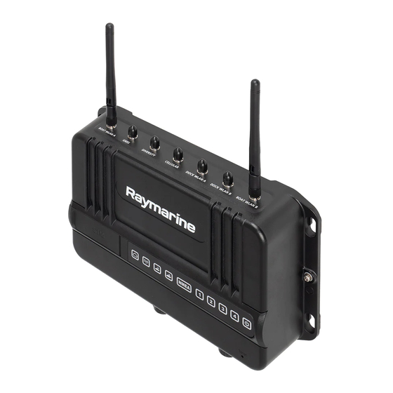
The following documentation is applicable to your product: smart router that provides a Wi-Fi hotspot and/or Ethernet internet connection This and other Raymarine product documents are available to download in to other devices on your vessel, and also enables remote monitoring and PDF format from www.raymarine.com. -
Page 14: Yachtsense Link System Diagram
Mandatory grounding connection above. 8. 12 V / 24 V dc router power supply 9. RayNet connection to MFD (direct or via Raymarine network switch) YachtSense Link system diagram 10. Router output channel connections (rated at 200 mA; for controlling... - Page 15 YachtSense ™ Link Marine Cloud Router (supplied with grounding point fixings and protective caps fitted). 2. 4 x mounting fixings (PA 4 x 25 mm self tapping screws). 3. Documentation pack 4. 5-in-1 antenna (GNSS, Cellular, Diversity, DOCK WLAN) with 5 m (16.4 ft) cables and M20 nut and mounting gasket.
-
Page 16: Chapter 3 Yachtsense Ecosystem
3.3 Off boat premium features — page 19 • 3.4 Raymarine app — page 19 • 3.5 Removing a boat system — page 22 • 3.6 Removing a router — page 22 • 3.7 YachtSense Link router account transfer / ownership transfer — page 23... -
Page 17: Yachtsense Ecosystem
On boat monitoring and control can be • The router also requires a RayNet connection to the YachtSense Digital achieved using a Raymarine Axiom MFD or the Raymarine app installed on Control System’s master module and any MFDs. - Page 18 Raymarine app connected to YachtSense ™ Link router with YachtSense ™ Digital Control System The following features are available when using the Raymarine app on a mobile device that is connected to the YachtSense ™ Link router’s Wi-Fi access point: •...
-
Page 19: Off Boat Premium Features
The YachtSense ™ ecosystem provides off-boat features that can be used installed from the relevant app store. whilst away from your vessel. You will need to create a Raymarine account to log in to the app. Note: How to connect guide •... -
Page 20: Transferring Lighthouse Charts
(Wi-Fi and / or cellular (mobile) connections) you can use the 2. Select Charts. Raymarine app to create a boat system and link your router to your Raymarine account. Linking allows off boat monitoring and control of compatible If you have already purchased charts then the My charts menu will show systems connected to your router. -
Page 21: Geofencing
Router’s network. Geofencing is available with a premium Raymarine app subscription. • When connected to a boat system that includes a YachtSense Link router you can view the status of the input channels and switch the output Geofence channels on and off from the Control tab. -
Page 22: User Access Management
Boat systems 4. Select Remove and then confirm the removal You can create / connect up to 10 boat systems to the Raymarine app. With 5. You must also unsync the MFD from the Raymarine app by accessing an active premium Raymarine app subscription up to 2 boat systems can be the My data menu on your MFD and selecting Mobile sync and Cancel configured to receive premium features. -
Page 23: Yachtsense Link Router Account Transfer / Ownership Transfer
3.7 YachtSense Link router account transfer / ownership transfer Yachtsense Link routers can only be linked to one account at a time. To link the router to a different account it must first be removed from the existing account (“Offboarding”). For instructions refer to: p.22 —... -
Page 24: Chapter 4 Installation
CHAPTER 4: INSTALLATION CHAPTER CONTENTS • 4.1 Tools required — page 25 • 4.2 Selecting a location — page 25 • 4.3 YachtSense ™ Link product dimensions — page 28 • 4.4 5-in-1 antenna dimensions — page 29 • 4.5 Inserting SIM cards — page 29 •... -
Page 25: Tools Required
4.1 Tools required YachtSense ™ Link location requirements The installation location must take into account the following requirements: The following tools are required for installation. This product is not suitable for installation in above decks locations, unless installed in a suitable protective enclosure. In this scenario, it’s important to avoid using enclosure materials that will have a significant impact on the wireless signals, such as conductive materials like steel or carbon fibre, for example. -
Page 26: Mounting Surface Requirements
• Other wireless-enabled products Note: • Transmitting products that send wireless signals in the same frequency Crew members (especially when wet) can also be obstructive to wireless range signals, if their bodies pass through the signal area between wireless sensor and any associated displays. •... -
Page 27: Rf Interference
Correct installation is required to ensure that EMC performance is not maintenance), it must be replaced in the original position before the compromised. product is used. • Use only ferrites of the correct type, supplied by Raymarine or its authorized dealers. Installation... -
Page 28: Connections To Other Equipment
Requirement for ferrites on non-Raymarine cables. If your product is to be connected to other equipment using a cable not supplied by Raymarine, a suppression ferrite MUST always be attached to the end of the cable nearest to the Raymarine product. -
Page 29: 5-In-1 Antenna Dimensions
• J = 229.00 mm (9.02 in) 1. Open the SIM card door. • K = 242.00 mm (9.53 in) • L = 63.00 mm (2.48 in) 4.4 5-in-1 antenna dimensions 2. Slide the SIM card holder(s) into the unlocked position. SIM 1 slides to the left and SIM 2 slides to the right. - Page 30 6. Slide the SIM card holder(s) into the locked position. 4. Ensuring correct orientation, insert your Micro SIM card(s) into the holders. SIM 1 slides to the right and SIM 2 slides to the left. 7. Close the SIM card door, ensuring that it is correctly seated all the way around the edge.
-
Page 31: Mounting The Yachtsense ™ Link
4.6 Mounting the YachtSense ™ Link Follow the instructions below to mount the YachtSense ™ Link. 1. Fix the supplied mounting template to the chosen location using masking or self-adhesive tape. Before mounting the product ensure that you have: 2. Drill 4 holes as indicated on the template to accept the fixings. •... -
Page 32: Mounting The 5-In-1 Antenna
4.7 Mounting the 5-in-1 antenna 3. Feed the cables and thread through the hole in the mounting surface so that the gasket and antenna sit flush on the mounting surface. The supplied 5-in-1 antenna must be installed in a location which has a clear 4. -
Page 33: Chapter 5 Connections
CHAPTER 5: CONNECTIONS CHAPTER CONTENTS • 5.1 General cabling guidance — page 34 • 5.2 YachtSense Link system diagram — page 34 • 5.3 Connections overview — page 35 • 5.4 MFD connections — page 35 • 5.5 YachtSense ecosystem — page 36 •... -
Page 34: General Cabling Guidance
It is important to use cables of the appropriate type and length. • Unless otherwise stated only use cables supplied by Raymarine. • Where it is necessary to use non-Raymarine cables, ensure that they are of correct quality and gauge for their intended purpose. (e.g.: longer power cable runs may require larger wire gauges to minimize voltage drop along the run). -
Page 35: Connections Overview
9. RayNet connection to MFD (direct or via Raymarine network switch) 5. Dock WLAN A (External dock Wi-Fi antenna connection) 10. Router output channel connections (rated at 200 mA; for controlling 6. Dock WLAN B (External dock Wi-Fi antenna connection) -
Page 36: Yachtsense Ecosystem
5.6 Power connection connected vessel systems and data. On boat monitoring and control can be achieved using a Raymarine Axiom MFD or the Raymarine app installed on a mobile phone or tablet. Off boat monitoring and control can be achieved The supplied power cable must be connected to a 12 V dc or 24 V dc power using the Raymarine app. -
Page 37: In-Line Fuse And Thermal Breaker Ratings
Implementation — connection to distribution panel (Recommended) number of devices you are connecting. If in doubt consult an authorized Raymarine dealer. • Your product’s power cable may have an in-line fuse fitted, if not then you must add an in-line fuse / breaker to the positive wire of your product’s power connection. - Page 38 • If the power cable is NOT supplied with a fitted inline fuse, you MUST fit a suitably rated fuse or breaker between the red wire and the battery’s positive terminal. • Refer to the inline fuse ratings provided in the product’s documentation. •...
-
Page 39: Grounding Connection
Power cable extension • BMEA Code of Practice for Electrical and Electronic Installations in Boats If you need to extend the length of the power cable supplied with your • NMEA 0400 Installation Standard product, ensure you observe the following advice: •... -
Page 40: 5-In-1 Antenna Connections
5.8 5-in-1 antenna connections The supplied 5-in-1 antenna is connected to the antenna connections on the top of the YachtSense ™ Link unit. Vessel grounding point. 2. M3 size ring crimp (not supplied). 3. Grounding strap connected to vessel RF ground (not supplied). 4. -
Page 41: Antenna Extension Kit
5.9 Boat Wi-Fi antenna connections Antenna extension kit The 5 m (16.4 ft) antenna cables on the supplied 5-in-1 antenna can be The supplied Wi-Fi antennas are connected to the BOAT Wi-Fi connections extended by 5 m (16.4 ft), using the antenna cable extension kit (A80701). on the top of the YachtSense ™... -
Page 42: Raynet Connections
SeaTalkng ® spur cable. Connection to a SeaTalkng ® backbone enables compatible data to be received and transmitted by the router. The SeaTalkng ® connection also enables communications with Raymarine Axiom™ MFDs and Raymarine YachtSense ™ Digital Control Systems. -
Page 43: Input And Output Channels
• The router’s input and output channels enable creation of a simple digital monitoring / control system. As device connections are outside of Raymarine’s control the company will not be held liable for damage or injury caused due to incorrect connections. -
Page 44: Output Channel Wiring
• Gray = Output 3 Common terminal (COM) • Red = Output 4 Normally open terminal (N/O) • Brown = Output 4 Common terminal (COM) The output channels can be controlled from the YachtSense ™ Link web interface or from the Raymarine app. -
Page 45: Output Channel Connections
Output channel connections Example automotive 4 or 5 pin relay type B connection diagram The output connection includes 4 configurable output channels. Output channels are intended to be connected to devices via an automotive relay. It is NOT intended that devices are connected directly to the output channels. Note: •... -
Page 46: Chapter 6 Operations
6.5 Connected devices page — page 55 • 6.6 Advanced settings — page 55 • 6.7 Help — page 59 • 6.8 YachtSense Link router account transfer / ownership transfer — page 59 • 6.9 Boat system and router removal (Offboarding) — page 59... -
Page 47: Getting Started
The router’s settings are accessed using the built-in web interface. The web Accessing the web interface using a wired connection interface can be accessed using a wired connection to a Raymarine MFD The router’s settings are accessed using the built in web interface. The web running the LightHouse™... -
Page 48: Accessing The Web Interface Using A Wi-Fi Connection
IP address. Your router’s IP address can be found on an MFD’s Network settings tab: Homescreen > Settings > Network. Then select Raymarine Yachtsense Link from the list of network devices, and select the Product Info option, alternatively you could use a network discovery tool to identify the router’s IP address. -
Page 49: Accessing Settings Pages
5. Open a web browser on your connected mobile device. Note: Enter ‘http://yachtsense.raymarine.com’ or your router’s IP address into Pre-pay / Pay As You Go (PAYG) SIM cards require activation and top up your web browser’s address bar and press Enter/Return. -
Page 50: Connecting To An Available Wi-Fi Network
Connecting to a Wi-Fi network manually 8. To save all changes, select the Save button located at the top of the page. You can connect to a network that is not in the list but is in range, i.e.: a Wi-Fi Manual APN settings configuration network that is not broadcasting its SSID. -
Page 51: Network Security
• Use a strong router access point password (i.e. a longer password such as a memorable phrase). • Change your password periodically. • Be cautious who you share your password with. • If you need to write down your password, ensure it is kept in a secure place where it is not easily viewable. -
Page 52: Connecting An Ios Device To The Router's Wi-Fi Access Point
(Wi-Fi and / or cellular (mobile) connections), you can use the Open your iOS device’s Wi-Fi settings from the top drop down menu or via Raymarine app to create a boat system and link your router to your Settings. -
Page 53: Status Page
• The Cloud section identifies the status of the router’s connection to the to the router’s cellular connection, SIM management options and mobile data Raymarine cloud service. usage statistics. When a SIM card is inserted in to the router’s SIM card slot •... -
Page 54: Access Point Page
• Data warning and limit — set data warning and limit so that you do not Important: If the APN you require is not listed or you’re unable to exceed your data allowance. You will be notified by the Raymarine app connect to the Internet using the current APN settings, you will need to when the specified data warning and data limit for the month has been modify an existing APN by selecting the “pencil”... -
Page 55: Info Page
A QR code is available at the bottom of the Info page that can be used to link connecting devices to be automatically assigned an IP address within the your router to a Raymarine cloud account. range you specify in the DHCP server. -
Page 56: Wi-Fi Configuration Page
Wi-Fi configuration page • Satellites in use — Provides details of the positioning satellites currently being tracked. The Wi-Fi configuration page provides IP address details and configuration settings for the router’s Wi-Fi access point connection. Inputs and outputs Important: Settings and status pages are available for the management of devices IP configuration is for advanced users and should not be changed, unless connected to the router’s inputs &... -
Page 57: Output Channel Configuration
Channel name field. In low power mode the router can be woken by: Alert notifications page • a remote device connected to the Raymarine cloud service, via the Raymarine app. Alert notifications can be configured for the router’s supply voltage and input •... -
Page 58: Performing A Router Software Upgrade
NOT disconnect the device you are upgrading from until the process is complete. 1. Open the Raymarine app on your mobile device and log in if required. Once the process is complete the router will reboot. 2. Select the menu icon located on the left of the screen to open the side... -
Page 59: Changing The Admin Password
6. Access the router’s web interface: 7. Select Restart & factory reset from the router’s Advanced settings menu. Yachtsense Link routers can only be linked to one account at a time. 8. Select Reset to factory defaults. To link the router to a different account it must first be removed 9. -
Page 60: Removing A Router
Removing a router You can remove a YachtSense Link router from a boat system in the Raymarine app by following the steps below. 1. Select the menu icon located on the left of the screen to open the side menu. -
Page 61: Chapter 7 Troubleshooting
CHAPTER 7: TROUBLESHOOTING CHAPTER CONTENTS • 7.1 Troubleshooting — page 62 • 7.2 LED diagnostics — page 62 • 7.3 Power up troubleshooting — page 63 • 7.4 Wi-Fi troubleshooting — page 64 • 7.5 Web interface access troubleshooting — page 65 •... -
Page 62: Troubleshooting
(Amber) Connected to 2G/3G. Before packing and shipping, all Raymarine products are subjected to comprehensive testing and quality assurance programs. If you do experience problems with your product, this section will help you to diagnose and correct problems to restore normal operation. -
Page 63: Power Up Troubleshooting
Dock WLAN LED (Amber) Port connected 10/100 Mbits/s. (Green) Connected to Wi-Fi. (Amber) Transferring data 10/100 Mbits/s. (Green) Connected to Wi-Fi and transferring data. Power LED (Red) Unable to connect to Wi-Fi / No signal. (Green) Powered up / Ok. (Off) Wi-Fi switched off. -
Page 64: Wi-Fi Troubleshooting
2. Check the condition of relevant / additional fuses and breakers and • Router not broadcasting — Ensure that the router you are trying to connections; replace if necessary. connect to is broadcasting its SSID. If you have no control over the router’s settings or do not want the router to broadcast its SSID then you will need 3. -
Page 65: Web Interface Access Troubleshooting
IP address can be found on an MFD’s Network settings tab: Homescreen > signal. Temporarily switch off devices in turn until you have identified the Settings > Network. Then select Raymarine Yachtsense Link from the list of device causing the interference, then remove or reposition the offending network devices, and select the Product Info option, alternatively you could device(s). -
Page 66: Password Reset (Forgotten Password)
If the APN you require is not listed or you’re unable to connect to the Internet using the current APN settings, you will need to modify an existing APN by selecting the “pencil” Edit icon on the right: You will need to obtain the APN settings from the SIM card network provider. -
Page 67: Performing A Network Settings Reset
7.8 Performing a network settings reset 7.9 Performing a hard reset If you have lost or can no longer remember the router’s admin password you If the router’s web user interface becomes inaccessible then you can perform can perform a networking reset following the steps below. a hard reset of the router following the steps below. -
Page 68: Chapter 8 Maintenance
CHAPTER 8: MAINTENANCE CHAPTER CONTENTS • 8.1 Service and maintenance — page 69 • 8.2 Product cleaning — page 69 • 8.3 Product returns — page 69... -
Page 69: Service And Maintenance
• Do NOT use a jet wash. 8.3 Product returns If you need to return your YachtSense Link router for service or repair you must remove it from your boat system first. For instructions refer to: 6.9 Device removal... -
Page 70: Chapter 9 Technical Support
CHAPTER 9: TECHNICAL SUPPORT CHAPTER CONTENTS • 9.1 Raymarine product support and servicing — page 71 • 9.2 Frequently Asked Questions (FAQs) — page 72 • 9.3 Learning resources — page 72 • 9.4 Product returns — page 72... -
Page 71: Raymarine Product Support And Servicing
Raymarine offers dedicated service departments for warranty, service, and • E-Mail: support.it@raymarine.com repairs. • Tel: +39 02 9945 1001 Don’t forget to visit the Raymarine website to register your product for Spain (Authorized Raymarine distributor): extended warranty benefits: http://www.raymarine.co.uk/display/?id=788. • E-Mail: sat@azimut.es United Kingdom (UK), EMEA, and Asia Pacific: •... -
Page 72: Frequently Asked Questions (Faqs)
9.2 Frequently Asked Questions (FAQs) 9.4 Product returns A range of FAQs is available on the Raymarine website to assist you in using If you need to return your YachtSense Link router for service or repair you and troubleshooting your product. -
Page 73: Chapter 10 Technical Specification
CHAPTER 10: TECHNICAL SPECIFICATION CHAPTER CONTENTS • 10.1 YachtSense Link technical specification — page 74 Technical specification... -
Page 74: Yachtsense Link Technical Specification
10.1 YachtSense Link technical specification Wireless networks specification BOAT Wi-Fi: Wi-Fi access point mode Power specification frequencies: • 2.4 GHz:(2412 MHz to 2472 MHz Nominal supply voltage: 12 / 24 V dc / 2422 MHz to 2462 MHz): Operating voltage range: 8 V dc to 32 V dc 13.28 dBm... -
Page 75: Chapter 11 Spares And Accessories
CHAPTER 11: SPARES AND ACCESSORIES CHAPTER CONTENTS • 11.1 Spares and Accessories — page 76 • 11.2 RayNet to RayNet cables and connectors — page 77 • 11.3 RayNet to RJ45 adapter cables — page 78 • 11.4 SeaTalkng ® cables and accessories — page 80 Spares and accessories... -
Page 76: Spares And Accessories
• R70835 — YachtSense Link router only. • R70836 — Replacement Wi-Fi antenna pair. • R70799 — YachtSense Link power cable 1.5 m (4.9 ft) with 8 A fitted fuse. • R70837 — replacement 5-in-1 antenna. • R70870 — 5-in-1 antenna replacement gasket and nut. -
Page 77: Raynet To Raynet Cables And Connectors
11.2 RayNet to RayNet cables and connectors Standard RayNet connection cable with a RayNet (female) socket on both ends. 2. Right-angle RayNet connection cable with a straight RayNet (female) socket on one end, and a right-angle RayNet (female) socket on the other end. Suitable for connecting at 90°... -
Page 78: Raynet To Rj45 Adapter Cables
11.3 RayNet to RJ45 adapter cables Adapter cable with a RayNet (female) socket on one end, and a waterproof (female) socket on the other end accepting the following cables with an RJ45 SeaTalkhs ® waterproof locking (male) plug: • A62245 (1.5 m). •... - Page 79 2. Adapter cable with a RayNet (female) socket on one end, and a waterproof (female) RJ45 socket on the other end, along with a locking gland for a watertight fit. 3. Adapter cable with a RayNet (male) plug on one end, and an RJ45 SeaTalkhs ® waterproof (male) plug on the other end. 4.
-
Page 80: Seatalkng ® Cables And Accessories
11.4 SeaTalkng ® cables and accessories 2 x 5 m (16.4 ft) Backbone cables (A06036). Used to create and extend the SeaTalkng backbone. SeaTalkng ® cables and accessories for use with compatible products. 1 x 20 m (65.6 ft) Backbone cable (A06037). Used to create and extend the SeaTalkng backbone. - Page 81 2. 1 x 1 m (3.3 ft) Spur cable (A06039). Used to connect a device to the SeaTalkng backbone. 3. 1 x 1 m (3.3 ft) NMEA 0183 VHF stripped-end (2 wire) to SeaTalkng adapter cable (A06071). Used to connect an NMEA 0183 VHF radio to the SeaTalkng backbone via the NMEA 0183 VHF to SeaTalkng converter.
- Page 82 3. 1 m (3.3 ft) Elbow (right angled) to straight spur cable (A06081). Used in 2. 2 m (6.6 ft) Elbow (right angled) power cable (A06070). confined spaces where a straight spur cable will not fit. SeaTalkng ® connectors 4. SeaTalkng to stripped-end spur cables (Connects compatible product SeaTalkng connectors are used to connect SeaTalkng devices to the that do not have a SeaTalkng connector such as transducer pods): SeaTalkng backbone and to create and extend the backbone.
- Page 83 • 1 m (3.3 ft) SeaTalkng to DeviceNet (male) adaptor cable (A06076). • 1.5 m (4.92 ft) SeaTalkng to DeviceNet (male) adaptor cable (A06046). 6. 1 m (3.3 ft) NMEA 0183 VHF stripped-end (2 wire) to SeaTalkng adapter cable (A06071). Used to connect an NMEA 0183 VHF radio to the SeaTalkng backbone via the NMEA 0183 VHF to SeaTalkng converter.
-
Page 85: Appendix A Nmea 2000 Pgn Support
Appendix A NMEA 2000 PGN support • 127498 — Engine parameters, static (Receive) • 127501 — Binary status report (Receive) Administration PGNs • 127502 — Switch bank control (Receive/Transmit) • 59392 — ISO Acknowledge (Receive / Transmit) • 127503 — AC input status DEPRECATED (Receive) •... -
Page 86: Appendix B Document Change History
• Updated output channel connection details. • Added Raymarine app linking details. • Added router transfer of ownership details. • Added Raymarine app device removal details. • Updated input channel monitoring and configuration details using the web interface. • Updated alert notification details. - Page 89 Antenna extension cable................41 Voltage monitor ................... 44 APN settings....................50 Wi-Fi...................... 41 YachtSense Digital Control System ..........17, 36 YachtSense Link .................. 35 Contact details..................71 Beidou ..................... 56 Boat Wi-Fi connection LED diagnostics........... 62 Data limit....................54 Data roaming ................... 53 Data usage ....................
- Page 90 5-in-1 antenna ..................29 YachtSense Link .................. 28 Link router ....................52 Dock WLAN LED..................63 Location requirements Documentation 5-in-1 antenna ..................28 Installation instructions ................. 13 Wireless ..................25–26 Mounting template................13 Wireless interference................26 Operation instructions ................13 YachtSense ™...
- Page 91 Distribution ..................37 SIM info....................54 Distribution panel................. 37 Sleep ....................... 57 Grounding.................... 39 Software updates ................26, 58 Sharing a breaker ................37 Spares ..................... 76 Power cable extension ................39 Status page ..................... 53 Power LED diagnostics................63 Support forum ..................72 Product Suppression ferrites ................
- Page 92 Off-boat features...................19 On-boat features................... 17 YachtSense ecosystem ..............17, 36...
- Page 94 PO15 5RJ. United Kingdom. Tel: (+44) (0)1329 246 700 www.raymarine.co.uk Raymarine (US) 9 Townsend West, Nashua, NH 03063. United States of America. Tel: (+1) 603-324-7900 www.raymarine.com Raymarine Belgium BVBA (EU) Luxemburgstraat 2, 2321 Meer. Belgium. Tel: (+32) (0) 3665 5162 www.raymarine.com...