Samsung MWR-WG00JN Service Manual
Wired remote controller
Hide thumbs
Also See for MWR-WG00JN:
- Service manual (36 pages) ,
- User manual (28 pages) ,
- Installation manual (26 pages)

Related Manuals for Samsung MWR-WG00JN


Summary of Contents for Samsung MWR-WG00JN
- Page 1 Wired Remote Controller MODEL CODE : MWR-WG00JN MWR-WG00KN Wired Remote Controller Contents 1. Cautions 2. Features and Specifications 3. Disassembly and assembly 4. Troubleshooting 5. Parts layout 6. Wiring diagram 7. S/W Download...
-
Page 2: Table Of Contents
Contents 1. Precautions ............................1-1 1-1. Service Precautions ..........................1-1 1-2. Product Safety Precautions ......................1-1 2. Features and Specifications .........................2-1 2-1. Product Features ..........................2-1 2-1-1. Product Features ........................2-1 2-1-2. Changes compared to basic products................. 2-4 2-2. Product structure ..........................2-5 2-3. -
Page 3: Precautions
Cautions 1. Precautions 1-1. Service Precautions • When replacing electrical parts, be sure to use the rated parts. - Check the display of the model name, rated voltage, rated current, etc. of the electrical parts. • When repairing the fault, please repair the connection of HARNESS type firmly. - If the wiring is not good, abnormal noise or abnormal operation may occur. -
Page 4: Features And Specifications
Features and Specifications 2. Features and Specifications 2-1. Product Features 2-1-1. Product Features Color Graphic LCD (4.3 ") wired remote control with large screen - Floating Display for user-desired point function Master Slave Connect up to two wired remote controls. Wired remote control "indoor unit + ERV"... - Page 5 Features and Specifications Simple design to display various information Graphic Display Wired remote control. • TFT Color LCD Display - Provide needed screen / Icon (Provide big screen / Icon to improve visibility) <Fixed type black and white> <Floating Color Graphics> •...
- Page 6 Features and Specifications • Show additional information - Indication of indoor model information - Error list history display <Display of indoor unit model information <Error list display> (model code, S/No>...
-
Page 7: Changes Compared To Basic Products
Features and Specifications 2-1-2. Changes compared to basic products Basic Item Changes (MWR-WE13N) (MWR-WG00JN/MWR-WG00KN) Apply new CASE - CASE TOP - CASE BOTTOM CASE Applying new PBA ASSY Fixed LCD Display Display ASSY DISPLAY - Software code - Software code •... -
Page 8: Product Structure
Features and Specifications 2-2. Product structure [Unit : mm(inch)] 120.0 (4.72) 19.0(0.75) -
Page 9: Product Specification
Features and Specifications 2-3. Product Specification 2-3-1. Environment and Specification Classification Item Specification Remarks Use Aria Region of use (Korea) Refer to User's Manual General Type of use Wall-mount type, air conditioner Indoor unit Remote controller Refer to Conditions Installation Guide Accessory Contact Service Center Supply... -
Page 10: Feature Expansion Specification
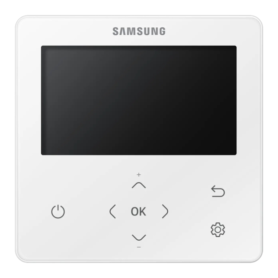
Features and Specifications 2-3-2. Feature expansion specification Indoor Ventilator ① ° ⑤ ⑥ ② ⑦ ③ ④ Name Function Display window Display operation mode and function setting status ① On/Off button (LED) Air conditioner/ERV : on/off ② Adjustment of the temperature of the up and down or function Up and down button ③... - Page 11 Features and Specifications Feature expansion specification Indoor Ventilator OFF Current ① ② ③ ⑤ Cool High Wide Wind-Free ④ ⑥ Name Function Set temperature Set temp ① Current temperature Current temp ② Operation mode Auto, Cool, Dry, Fan, Heat ③ Air flow mode Auto, Turbo, High, Medium, Low ④...
- Page 12 Features and Specifications Feature expansion specification Ventilation system ① ② ③ Name Function Current temperature display Current temperature ① Operation mode display Heat, Auto, Normal, Quiet and Go out ② Wind strength indicator Auto, Turbo, Strong and Weak winds ③ Icon Description Icon Description...
- Page 13 Features and Specifications Feature expansion specification Air conditioner ② ③ Indoor Settings LONG ① ④ Sleep Long WindS chedule OFFO ⑤ ⑦ Purify Air Quality EnergyO ption ⑥ ⑧ Name Function Quiet Quiet mode On/Off ① Sleep Sleep mode On/Off ②...
- Page 14 Features and Specifications Feature expansion specification ② ③ ① ④ E-SaverS chedule Option Name Function Clean-up display Clean-up operation ① Power saving display Power saving operation ② Simple booking, weekly schedule, annual schedule, holiday Schedule setting display ③ setting Additional function display Additional function ④...
- Page 15 Features and Specifications Feature expansion specification Indoor Settings LONG Sleep Long WindS chedule Purify Air Quality Energy Option 1. Press the button. 2. Press the button to select Option, and then press the button. 3. See the following pages to select the desired menu. Major Step 1 Step 2...
- Page 16 Features and Specifications Feature expansion specification Major Step 1 Step 2 Step 3 Step 4 Step 5 Description Default PM10 ON/OFF Air Purify PM2.5 ON/OFF Display PM1.0 ON/OFF All lock ON/OFF Operation ON/OFF Lock All mode ON/OFF Lock Auto mode ON/OFF Lock Cool mode...
- Page 17 Features and Specifications Feature expansion specification Major Step 1 Step 2 Step 3 Step 4 Step 5 Description Default Smart Reset Reset All User modes Use of wired remote ON/OFF controller DSP Cooling Set temp. / Indoor unit (Set temp range for auto Auto change Heating status value...
- Page 18 Features and Specifications Feature expansion specification Service mode Please enter your PASSWORD 1. If you want to use the various additional functions for your Wired Remote Controller, press the buttons at the same time for more than 3 seconds. • The password entry screen appears. 2.
- Page 19 Features and Specifications Feature expansion specification • Unavailable functions are marked inactive and they cannot be set. • If communication initialization is needed after the setting, the system will reset automatically and communication NOTE will be initialized. Major Step 1 Step 2 Step 3 Description...
- Page 20 Features and Specifications Feature expansion specification Major Step 1 Step 2 Step 3 Description Default Micom code Micom code Program version Micom code Device Touch code Touch IC code Information (Wired Remote Program version Modified date Controller) Graphic image Graphic image code Program version Modified date Erase All Service...
- Page 21 Features and Specifications Feature expansion specification Major Step 1 Step 2 Step 3 Description Default By-Pass mode ON/OFF ERV option Auto mode ON/OFF External control ON/OFF ON/OFF ON/OFF alternation operation / ON/OFF Alternation Outdoor air cooling operation for alternation operation different temp.
- Page 22 Features and Specifications Feature expansion specification Indoor unit/Ventilator option Product option Product option (1/5) (2/5) Target Address:20 00 00 Address Target Address Product option Installation option 1 Serial No.: Installation option 2 Press the button to set the current step. Press the button to set the current step.
- Page 23 Features and Specifications Feature expansion specification 1 Press the , and buttons at the same time for more than 3 seconds. 2 Enter the password, “0202,” and then press the button. 3 Press the , and buttons to select “Indoor Unit option,” and then press the button.
-
Page 24: How To Install
Features and Specifications 2-4. How to install 2-4-1. Wired remote control installation 1) Insert the flat-head screwdriver into two square grooves at the bottom of the Wired Remote Controller and rotate it to lift the front cover for removal from the rear cover. 2) Arrange the power cable and the communication cable so that they fit in the housing along the edges of the rear cover. - Page 25 Features and Specifications Wired remote controller installation 3) Using two or more screws, firmly affix the rear cover of the remote controller to the wall, and then cut off the grooves of the front covers for communication and power cables, making sure these cables have reasonable length. .4 inch) or more inch) or more inch) or more...
- Page 26 Features and Specifications Wired remote controller installation 5) Reassemble the Wired Remote Controller. • Align the controller with the upper groove first, and then insert it by turning it downwards as shown in the figure. After assembly, check and confirm that no wires are stuck in the gap between the back and front covers. NOTE 6) Remove the front protective film.
- Page 27 Features and Specifications Wired remote controller installation Scanning… 1 Tracking of your Wired Remote Controller will automatically start when you turn on the power after installation. 2 If you want to perform tracking again after installation, then press the and buttons at the same time for more than 5 seconds.
-
Page 28: Disassembly And Assembly
Disassembly and assembly 3. Disassembly and assembly Photo How to work 1. Use the flat-blade screwdriver to slide the bottom two grooves into the product Push CASE TOP up and remove CASE BOTTOM. • When assembling, assemble the upper side first as shown and lower Assemble with hook. - Page 29 Disassembly and assembly Photo How to work Remove the HOLDER DISPLAY hook assembled with the PBA. 4 Remove the LCD connector to separate the PBA and the ASSY Display.
-
Page 30: Troubleshooting
Troubleshooting 4. Troubleshooting 4-1. Things to check before diagnosis 4-1-1. Errors displayed on the Wired Remote Controller Error codes for the Wired Remote Controller and the product connected to your Wired Remote Controller will be displayed in the LCD display. Indication Description Remarks... -
Page 31: Action By Symptom
Troubleshooting 4-2. Action by symptom 4-2-1. When the LCD screen does not come out Start Is the connection to the Check the connection between F3F4 terminal block OK? F3 F4 cable and terminal block Is the voltage across the Check indoor power Replacement of Assy PCB C108 Is the voltage (DB92-04639A) due to 21V... -
Page 32: Parts Layout
Parts layout 5. Parts layout MICOM EEPROM IMAGE IC TOUCH IC ① ② ③ ④ MICOM (MB9BF416R) MEMORY Processor Display image Processor TOUCH Processor RTC IC Transformer Communicator part Super Capacitor ⑤ ⑥ ⑦ ⑧ Schedule, Time Processor Communicator signal Two Wired Communication Super capacitor for current Processor... -
Page 33: Wiring Diagram
Wiring diagram 6. Wiring diagram microSD SLOT Download Connecter Temperature Sensor Connecter F3F4 TerminalBlock... -
Page 34: S/W Download
S/W Download 7. S/W Download 1 Download the wired remote controller image, change the file name to “IMAGE.BIN,” and then download to microSD Card. 2 Download the wired remote controller program, change the file name to “MICOM.BIN,” and then download to microSD Card. 3 Insert the microSD Card with the Wired Remote Controller active, and then reset the system. - Page 35 China china.samsungportal.com © Samsung Electronics Co., Ltd. April. 2019. This Service Manual is a property of Samsung Electronics Co., Ltd. Printed in Korea. Any unauthorized use of Manual can be punished under Code No.AC-00241E_1 applicable International and/or domestic law.