Table of Contents
Advertisement
Quick Links
Advertisement
Table of Contents

Related Manuals for Epson EU-m30 Series


Summary of Contents for Epson EU-m30 Series
- Page 1 Developer’s Guide *Includes information on OT-BU30. M00139800 EN Rev.A...
- Page 2 Neither is any liability assumed for damages resulting from the use of the information contained herein. Neither Seiko Epson Corporation nor its affiliates shall be liable to the purchaser of this product or third parties for damages, losses, costs, or expenses incurred by the purchaser or third parties as a result of: accident, misuse, or abuse of this product or unauthorized modifications, repairs, or alterations to this product, or (excluding the U.S.) failure to strictly comply with Seiko Epson Corporation’s operating and maintenance...
- Page 3 Important Safety Information This document presents important information intended to ensure safe and effective use of this product. Read this section carefully and store it in an accessible location. Safety Precautions WARNING: Handling the product improperly by ignoring this symbol can lead to death or serious injury. In the following cases, immediately turn off the power and contact qualified service personnel.
- Page 4 Caution Labels The caution labels on the product indicate the following precautions. CAUTION: Do not touch the thermal head and the frame on its side because it can be very hot after printing. CAUTION: The sharp edge can cut your fingers. Restriction of Use When this product is used for applications requiring high reliability/safety, such as transportation devices related to aviation, rail, marine, automotive, etc.;...
- Page 5 Product Overview This chapter describes features of the product. Features This product (printer unit) is intended to be integrated into a self-service terminal. For details on how to integrate it into a self-service terminal, refer to the following: Appendix M PRINTER INSTALLATION DESIGN GUIDE ...
- Page 6 Product Configurations Models Standard model Models for specified customers Accessories Included Main unit Roll paper (φ 35 mm) Switch cover For power switch For power/feed switch Small cover open lever, including 1 spare screw ...
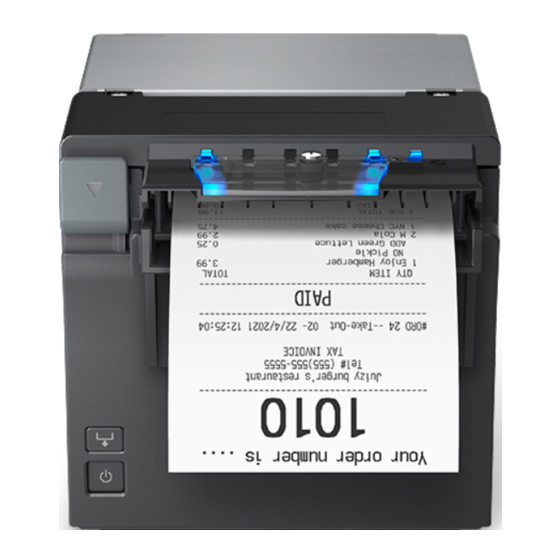
- Page 7 Part Names and Function Front Cover open lever Operate this lever to open the roll paper cover. Feed button Pressing this button once feeds roll paper for one line. Hold down this button to continue feeding roll paper. Power switch Turns the printer on or off.
-
Page 8: Outline
OUTLINE Scope of this document This document applies to the EU-m30 and bezel option OT-BU30. Product safety precautions Do not allow a voltage that exceeds the absolute maximum rating to be applied to the power connector. If the applied voltage exceeds the absolute maximum rating, excess current may flow, causing thermal damage to components. - Page 9 Caution Caution: Hot Surface (See Appendix B.) Caution: Sharp Edges (See Appendix P.)
-
Page 10: Table Of Contents
TABLE OF CONTENTS OUTLINE ....................................1 Scope of this document ............................1 Product safety precautions ............................1 TABLE OF CONTENTS ................................3 GENERAL SPECIFICATIONS ........................6 Print Specifications ..............................6 Character Specifications ............................6 Autocutter .................................. 6 Paper Sensor ................................7 Roll Paper Supply Device ............................ - Page 11 3.8.1 NV graphics information print mode ......................35 3.8.2 R/E (receipt enhancement) information print mode ................36 3.8.3 Software setting mode ........................... 36 3.8.4 Initial setting restoration mode ........................37 Error Processing ..............................37 3.9.1 Errors that recover automatically ........................ 37 3.9.2 Recoverable errors ............................
- Page 12 S.2.3 OPOS (OCX Driver) ............................75 S.2.4 OPOS for .NET ............................... 75 S.2.5 Epson ePOS SDK for Android ........................76 Controlling the Optional External Buzzer (Model for specified customer only) .......... 76 S.3.1 ESC/POS Command ............................76 S.3.2 For Windows Printer Drivers (APD) ......................76 S.3.3...
-
Page 13: General Specifications
GENERAL SPECIFICATIONS Print Specifications Print speed The maximum is 100 mm/s {3.94"/s} when printing ladder bar codes, 2-dimensional symbols, or multi-tone graphics. The print speed changes automatically depending on the voltage applied to the printer and the condition of the head temperature. -
Page 14: Paper Sensor
Paper Sensor Function Detects whether paper is present in the paper path. Method Microswitch Roll Paper Supply Device Use roll paper that is not deformed, and ensure there is no slack when setting. Function Supplies paper with a width of 80 mm {3.15"} or 58 mm {2.28"} Method Drop-in roll paper Paper Specifications... -
Page 15: Print Area
Print density adjustment depending on the specified original paper In order to ensure optimal print quality and reliability, we recommend using the print density settings in the table below. The initial setting is 100% print density. The print density can be changed using customized values. ... - Page 16 Emergency cutting position Autocut position Print position Figure 1.8.1 Printing and Cutting Positions These values are the design center values for the position of the structures, and vary from the top margin values. When setting the cut position, take into account that values may vary as a result of paper slack or variations in the paper.
-
Page 17: Internal Memory
Internal Memory Receive buffer 4 KB or 45 bytes (Select using software settings) Downloaded character area 12 KB (Shared with the downloaded bit image area) Macro area 2 KB NV graphics area 384 KB Downloaded graphics area 208 KB NV user memory area 1 KB 1.10 Electrical Characteristics... - Page 18 (a) When paper width is set to 80mm {3.15"} Table 1.10.1 Current Consumption (Operating) (when paper width is set to 80 mm {3.15"}) Print ratio Approximately 18% (with 100% the print pattern below) (Printing length: 20 mm (Printing length: 20 mm Font A, ANK rolling {0.79"}) {0.79"})
-
Page 19: Emi And Safety Standards Applied
Note: Printing with this product is assumed to be receipts or the equivalent. If printing is continuously performed with a high print ratio, the overcurrent limitation may be operated. Therefore, the printing length must not exceed 20mm {0.79"} when printing with 100% print ratio. AC power consumption (AC100 to 230 V / 50 to 60 Hz) ... -
Page 20: Reliability
1.12 Reliability Life Printer mechanism: 17 million lines (Repeating 10 line-printing + 5 line-paper feeding) Print head 150 km Autocutter 1,500,000 cuts (At room temperature and normal humidity with specified original paper type no. being TF50KS-EY, PD160R, KT55FA) Note: End of life is defined as the point at which the component reaches the beginning of the wearout period. - Page 21 Test result No visible exterior or interior damage, and no abnormal operation. Impact resistance (a) When packed Drop conditions Packing method: Epson standard package Height: 60 cm {23.62"} Directions: 1 corner, 3 edges, and 6 surfaces Test method After dropping under the above conditions, visually inspect the interior and exterior and check operation.
-
Page 22: Installation
X direction Figure 1.13.2 Direction of Impact Acoustic noise (a) Operation noise Test conditions: Epson standard Test method: Epson standard Measuring result: Approx. 60 dB (Bystander position) Note: Measured value fluctuates depending on the paper used and the print conditions (print pattern, print speed, print density, etc.). -
Page 23: Usb Interface
1.15.2 USB interface USB connector Type USB upstream port connector (USB type-B connector) Pin assignments Pin number Signal name VBUS Shell Shield USB communication specifications (a) USB functions Overall specifications: Complies with USB 2.0 Communication speed: Full-Speed (12 Mbps) ... - Page 24 [00H][XXH] *1 MFG:EPSON; CMD:ESC/POS; MDL:EU-m30; *2 CLS:PRINTER; DES:EPSON[SP]EU-m30; *2 CID:EpsonTM00001021; *2 *1: DeviceID character string size *2: The character string depends on the language model and mode. SOFT RESET The host computer uses this USB Device Request when initializing the printer input buffer.
-
Page 25: Rs-232 Serial Interface
1.15.3 RS-232 serial interface Connectors Type D-SUB9 (Male) Pin assignments Pin number Function – – – Shell Shield Specifications (Complies with RS-232) Data transmission method: Serial Synchronization: Asynchronous Handshaking: DTR/DSR or XON/XOFF control Signal levels: MARK = -3 to -15 V: Logic "1"/ OFF SPACE = +3 to +15 V: Logic "0"/ ON Transmission speeds: 2400, 4800, 9600, 19200, 38400, 57600, 115200 bps... - Page 26 Interface connector terminal assignments and signal functions Table 1.15.1 Signal Layout and Functions Signal Signal Function number name direction Input Data reception Output Data transmission Output When DTR/DSR control is selected: This signal indicates whether the printer is busy. SPACE indicates that the printer is ready to receive data, and MARK indicates that the printer is busy.
- Page 27 (1) If Memory switch 5-2 is OFF: The printer status becomes "buffer full" from when the remaining space in the receive buffer drops to 128 bytes until such time that the remaining space in the receive buffer increases to 256 bytes. (2) If Memory switch 5-2 is ON: The printer status becomes "buffer full"...
-
Page 28: Connectors
When setting Memory switch 1-3 to ON to enable handshaking with the printer, be sure to check the printer status using the GS a command and the automatic status back function of the data dependent on that command. In this setting, the default value of n for GS a is 2. The printer automatically transmits the printer status when the online/offline status changes. -
Page 29: Drawer Kick Connector (Modular Connector) *For Specified Customer Only
1.16.3 Drawer kick connector (modular connector) *For specified customer only Function Connect to the drawer or the optional external buzzer. The pulse specified by the ESC p or DLE DC4 command is output to this connector. The host computer can confirm the status of the input signal by using the DLE EOT, GS a, or GS r command. Pin assignments Pin number Signal name... - Page 30 Drawer open/close signal Drawer-kick connector F. G Shielded Drawer-kick solenoid Control device P-GND +24V Drawer open/close switch P-GND Printer side User side (Drawer side) Figure 1.16.2 Drawer Kick Connection Diagram Use a shielded cable for the drawer connector cable. ...
-
Page 31: Allowable Interface/Power Supply Cable Dimensions
1.16.4 Allowable interface/power supply cable dimensions <USB cabel> <Serial cable> (Type-B Plug) <Power supply cable> Note: User must confirm that the connector plug and cable fit in the storage space. -
Page 32: Structure
Structure EU-m30, Standard model Exterior 1: Cover open lever 2: Feed button 3: Power switch Interfaces equipped USB and serial (RS-232, D-Sub 9 pin) Connector layout 1: Power supply connector 2: USB connector (Type-B) 3: Serial connector Accessories Roll paper (φ 35 mm) ... -
Page 33: For Specified Customer
For specified customer Exterior Same as EU-m30 (See 2.1.(1).) Interfaces equipped USB and serial (RS-232, D-Sub 9 pin) Connector layout 1: Power supply connector 2: USB connector (Type-B) 3: Serial connector 4: DK connector Accessories Roll paper (φ 35 mm) ... -
Page 34: Function
Function Control Commands See "ESC/POS Command Reference" (www.epson-biz.com/pos/reference/). Character Code Tables See "Character Code Tables for TM Printers"(www.epson-biz.com/pos/reference/). Switches 3.3.1 Power switch Type Locking push switch Function (a) Turn the power on or off. Notes: Operate the power switch with the power connector connected. -
Page 35: Indicators
Indicators 3.4.1 Displayed color and icon 1: POWER LED (Blue) 2: ERROR LED (Orange) 3: Flashing LED (Blue) 3.4.2 Displayed patterns Printer status icon POWER ERROR Flashing Normal status On or [Off]*3 Initializing after power-on Executing self-test Continued self-test standby Flashing - (1) Paper is being fed by the Feed button Macro execution standby... -
Page 36: Printer Setting
Change settings with GS ( E <Function 3>. Step 3: End the user setting mode with GS ( E <Function 2>. For details, see "ESC/POS Command Reference" (www.epson-biz.com/pos/reference/). (b) Software setting mode (except some functions) For details, see 3.8.3 Software setting mode. - Page 37 Change the setting with GS ( E <Function 5>. Step 3: End the user setting mode with GS ( E <Function 2>. For details, see "ESC/POS Command Reference" (www.epson-biz.com/pos/reference/). (b) Software setting mode (except some functions) For details, see 3.8.3 Software setting mode.
- Page 38 Function Selectable values Factory setting Selection of the interface Fixed to serial interface All interfaces enabled Fixed to built-in USB Serial/USB automatic switching All interfaces enabled Command execution (offline) Enabled/Disabled Enabled Specification for the top margin by backfeed *3 9.5 to 2 mm (in 0.5 mm units) 9.5 mm {0.37"} Switchover time for a valid interface 1 to 10 seconds (1 second units)
- Page 39 (1) Moves to the user setting mode with GS ( E <Function 1> command. (2) Change settings with GS ( E <Function 11>. (3) End the user setting mode with GS ( E <Function 2> command. * For details, see "ESC/POS Command Reference" (www.epson-biz.com/pos/reference/). Software setting mode See 3.8.3. Software setting mode.
- Page 40 Receipt enhancement setting Can be changed using one of the following methods. (a) Group of commands for receipt enhancement control: FS ( E For details, see "ESC/POS Command Reference" (www.epson-biz.com/pos/reference/). (b) EU-m30 Utility (except some functions) Table 3.5.7 Receipt Enhancement...
-
Page 41: Self-Test
Self-test 3.6.1 Self-test function Executes printer status printing and rolling pattern printing. (a) Printer status printing Product name Firmware version Product serial number Interface information Built-in character fonts Maintenance information (Head running length, number of times of autocutting) (b) Rolling pattern printing ... -
Page 42: Information Print Modes And Setting Modes
(b) Executing using a command Step 1: Transmit the GS ( A command (Hexadecimal dump print). Step 2: Turn off the power, or press the Feed button three times to complete this procedure. Notes: If no characters correspond to the data received, the printer prints ".". ... -
Page 43: R/E (Receipt Enhancement) Information Print Mode
3.8.2 R/E (receipt enhancement) information print mode R/E (receipt enhancement) information printing function Prints the following R/E information presently registered in the printer. The following information is printed. Auto top logo print setting Auto bottom logo print setting ... -
Page 44: Initial Setting Restoration Mode
Starting the mode Step 1: With the roll paper cover closed, turn the printer power on while pressing the Feed button until printing of the printer status starts. Step 2: After the printer status is printed, press the Feed button until printing of the instructions for operation method starts. -
Page 45: Recoverable Errors
3.9.2 Recoverable errors Autocutter error Error contents: Detected an error in the autocutter operation. LED display pattern: See 3.4.2. Recovery method: Execute DLE ENQ 1 and DLE ENQ 2. Remove any paper jams or foreign objects and close the roll paper cover. Note: See Appendix A if this does not solve the error. -
Page 46: Print Buffer-Full Printing
3.11 Print Buffer-full Printing When in Standard mode When subsequent data is received after the printer processes one line of data in the print buffer, the printer automatically prints the processed line and feeds the paper by one line. When in Page mode When subsequent data is received after the printer processes one line of data in the print buffer, the printer automatically moves the printing position to one line below the processed line. -
Page 47: Printing Using Multiple Interfaces
DLE DC4 (fn = 2), ESC &, ESC ?, GS ( D, GS ( L <Functions 81,82,83>, GS *, GS :, GS D <Function 83>, GS ^, FS 2 (*3) If you are using ePOS-Print SDK or Epson ePOS SDK, the maintaining or initializing of print settings when closing the connection does not affect the operations of the application. (*4) For the method to set the receive buffer capacity, see Section 3.5.2 Software setting, (1) Memory switches. - Page 48 Note: Do not to turn off the printer's power while the firmware update tool is performing the update. Recovery method for when updating the firmware fails If updating the firmware fails, and the Power and Error LEDs flash at the same time when the power is turned on, try updating the firmware again by using the firmware update tool.
-
Page 49: Case Specifications
Width: Approximately 127 mm {5"} Depth: Approximately 155.9 mm {6.14"} Height: Approximately 127 mm {5"} Approximately 129 mm {5.1"} (including protrusions) Mass: Approximately 1.3 kg {2.87 lb} (roll paper excluded) Color EPSON standard color: ENB9, EBCK... -
Page 50: External Dimensions
External Dimensions 4.3.1 Bezel Option Not Equipped [Units: mm] Figure 4.3.1 External Dimensions (Bezel Option Not Equipped) -
Page 51: Bezel Option Equipped
4.3.2 Bezel option equipped [Units: mm] Figure 4.3.2 External Dimensions (Bezel Option Equipped) -
Page 52: Dimensions For Installing To Customer Device
Dimensions for Installing to Customer Device See Appendix M. -
Page 53: Appendix Arecovery From An Autocutter Error
Appendix A RECOVERY FROM AN AUTOCUTTER ERROR If You Can Open the Roll Paper Cover If a foreign object such as a push pin or paper clip drops in the autocutter and causes the autocutter to lock up, the printer enters an error state and begins the recovery operation automatically. ... -
Page 54: Appendix Bprint Head And Platen Roller Cleaning
Appendix B PRINT HEAD AND PLATEN ROLLER CLEANING Thermal Head Paper dust or other foreign objects on the thermal elements may lower the print quality. In this case, clean the print head as follows: Step 1: Open the roll paper cover. Step 2: Clean the thermal elements of the print head using a cotton swab moistened with alcohol solvent (ethanol or IPA). -
Page 55: Appendix Cnotes On Using The Drawer Kick Connector *For Specified Customer Only
Appendix C NOTES ON USING THE DRAWER KICK CONNECTOR *For specified customer only Conditions for Using the Drawer Kick Connector Drawer specifications differ significantly depending on the manufacturer and the model. Make sure that the specifications of the drawer used meet the following conditions when connected to the drawer kick connector. These conditions also apply to any other devices to be connected to the drawer kick connector. -
Page 56: Using A Drawer That Does Not Meet The Conditions In C.2 (Esc P, Dle Dc4)
Figure C.1.1 shows the drive signal waveform generated when the drawer is driven according to the above conditions. t1 × 2 ms t2 ≥ (t1 × 4) × 2 ms Figure C.1.1 Drawer Drive Signal Waveform The ON time depends on the specifications of the drawer used. Be sure to check the drawer specifications and set a suitable time. - Page 57 The drive signal waveform generated when the drawer is driven according to the above conditions is shown in Figure C.1.2. 200 ms 500 ms α = 300 ms Figure C.1.2 Drawer Drive Signal Waveform...
-
Page 58: Appendix D Notes On Updating The Maintenance Counter And Turning The Printer'spower Off
Appendix D NOTES ON UPDATING THE MAINTENANCE COUNTER AND TURNING THE PRINTER'S POWER OFF About Updating the Maintenance Counter This printer has a maintenance counter with functions as described in the command description for GS g 0 and GS g 2. ... -
Page 59: Appendix E Notes On Printing Bar Codes And 2-Dimensional Symbols
Appendix E NOTES ON PRINTING BAR CODES AND 2-DIMENSIONAL SYMBOLS User must set the quiet zone, depending on the bar code standards. When printing PDF417 (2-dimensional symbols), it is recommended to set the height of one step of the symbol to three to five times the width of one module. -
Page 60: Appendix Fnotes On Scanning The Print Result On The Receipt
Appendix F NOTES ON SCANNING THE PRINT RESULT ON THE RECEIPT To determine whether the ability of the reader (scanner) can be satisfied by using bar codes, 2-dimensional symbols, or characters printed on receipt (roll paper), take the following points into consideration. Print density The print density may vary depending on the type of roll paper or the environmental conditions. -
Page 61: Appendix Gnotes On Using The Asb Status
Appendix G NOTES ON USING THE ASB STATUS Any accumulated ASB status signals left for transmission from the last to the newest ASB status transmission shall be transmitted together at a time as one ASB status showing the presence of change, followed by the latest ASB status. -
Page 62: Appendix H Notes On Arp (Automatic Reduction Of Paper) And Automatic Logo Printing Function
Appendix H NOTES ON ARP (AUTOMATIC REDUCTION OF PAPER) AND AUTOMATIC LOGO PRINTING FUNCTION ARP: Reduction of Excessive Top Margin, Reduction of Excessive Bottom Margin, Reduction of Line Spacing, and Reduction of Line Spacing Where Extra Line Feeds Are Included ... -
Page 63: Appendix Isetting Paper Width
Appendix I SETTING PAPER WIDTH Notes If changing the paper width from 80 mm {3.15"} to 58 mm {2.28"}, install the included roll paper guides for 58 mm {2.28"} paper width. Be sure to set the paper width using software settings to align the print area. (For the setting method, see 3.5.2 (2).) Note: After changing the paper width from 80 mm {3.15"} to 58 mm {2.28"}, while using 58 mm {2.28"}, you are prohibited from changing the paper width again back to 80 mm {3.15"}. - Page 64 Step 3: Align the three protrusions of the other 58 mm {2.28"} width roll paper guide (not marked as L SIDE) with the slits on the opposite side of the printer, and insert them. Figure I.3 Step 4: Set the roll paper. Step 5: Close the roll paper cover, then turn the printer power on.
-
Page 65: Appendix Jnotes On Printing And Backfeed
Appendix J NOTES ON PRINTING AND BACKFEED If top margin specification via backfeed (3.5.2 (2)) is enabled, the backfeed operation is performed before starting printing directly after the autocut. If top eject, this backfeed operation is performed after the paper in the eject port is removed. -
Page 66: Appendix K Thai Character Printing
Appendix K THAI CHARACTER PRINTING To print using Thai characters, you can use the Thai character 1-pass print mode or Thai character 3-pass print mode. Select the Thai character print mode in the software settings. (See Section 3.5.2 for how to change the setting.) Character Size for Printing Thai Characters Table K.1.1 Thai Character Sizes (Thai Character 1-pass Print Mode) -
Page 67: Character Structure For Thai Character 1-Pass Print Mode
Character Structure for Thai Character 1-pass Print Mode 12dot 9dot Font A Font B Figure K.2.1 Thai Character 1-pass Print Mode Fonts A and B The numbers in the figure indicate the order in which character code data is transmitted. 12dot 9dot Special Font A... -
Page 68: Character Structure For Thai Character 3-Pass Print Mode
Character Structure for Thai Character 3-pass Print Mode 12dot 9dot 11 12 Font A Font B Figure K.3.1 Thai Character 3-pass Print Mode Fonts A and B The numbers in the figure indicate the order in which character code data is transmitted. 12dot 9dot 11 12... -
Page 69: Appendix Lusing A Power Supply Other Than The Ps-180
Appendix L USING A POWER SUPPLY OTHER THAN THE PS-180 If the power supply has low performance or the print duty is high, the power supply might become cut off. In such a cause, you may be able to avoid power supply cut-offs through the combination of the power supply capacity setting, print speed setting, and number of energized head divisions setting below. -
Page 70: Appendix M Printer Installation Design Guide
Appendix M PRINTER INSTALLATION DESIGN GUIDE Notes on Printer Installation Take into consideration paper ejection and dropping performance when designing the printer's paper discharge port. Because plated steel is used in this product, edges may be subject to rust. ... - Page 71 Fasten the two equipment mounting brackets, insert the printer from the interface side, and align the position such that the printer and bracket engagement points. Figure M.4 Positioning the Printer Insert the protrusions of the product fixing bracket into the equipment mounting bracket holes, and fasten with screws.
-
Page 72: Bezel Option Not Equipped
Bezel Option Not Equipped If impact may possibly be applied, provide support for the printer on the equipment side. Z direction: Printer support X direction: Printer support X direction: Printer support... - Page 73 X direction: Printer support Y direction: Printer support...
- Page 74 Bezel Option Equipped If impact may possibly be applied, provide support for the printer on the equipment side. Z direction: Printer support X direction: Printer support...
- Page 75 X direction: Printer support Y direction: Printer support...
-
Page 76: Appendix Ninstalling The Power Switch And Power/Feed Switch Cover
Appendix N INSTALLING THE POWER SWITCH AND POWER/FEED SWITCH COVER Installing the Switch Cover Step 1: Clean the area around the switch. Step 2: Peel off the switch cover's double-sided adhesive tape, and affix such that the switch cover's rear protrusions enter the power switch's recesses. -
Page 77: Appendix Oreplacement For Small Cover Open Lever
Appendix O REPLACEMENT FOR SMALL COVER OPEN LEVER To prevent malfunction, the cover open lever can be replaced with the included small cover open lever. Replacement for Small Cover Open Lever Step 1: Check that the printer's power is off, then open the roll paper cover. Step 2: Press down on the cover open lever and remove the cover open lever screw. -
Page 78: Appendix P Bezel Option (Ot-Bu30)
Appendix P BEZEL OPTION (OT-BU30) Notes on Using the Bezel Option (OT-BU30) A bezel option (OT-BU30) can be used with this printer. If using the bezel option (OT-BU30), the printer's paper can only be ejected in the front direction. Confirm that there is enough space even when the printer's roll paper cover is open. Installing the Bezel Option (OT-BU30) Step 1: Check that the printer's power is off, then open the roll paper cover. - Page 79 Figure P.3...
-
Page 80: Appendix Q Recommended Power Supply
Appendix Q RECOMMENDED POWER SUPPLY A power supply with a rating of 24 V/2.1 A or higher (50.6 W or higher) is recommended. If a power supply less than 24 V/2.1 A (less than 50.6 W) is used, printing may temporarily stop and uneven print density may occur. -
Page 81: Appendix R Printer Unit Handling
Appendix R PRINTER UNIT HANDLING When purchasing this product To prevent static electricity damage to thermal head elements and IC sensors, take steps to prevent static electricity and ensure that your body is grounded before handling the product. To prevent malfunction and static electricity damage to thermal head elements and IC sensors, ensure that the frame (casing) is properly grounded before installing the product. -
Page 82: Appendix S Application Development Information
S.1.1 ESC/POS ESC/POS is the Epson original printer command system for POS printers and customer display. With ESC/POS commands, you can directly control all the printer functions, but detailed knowledge of printer specifications or combination of commands is required, compared to using drivers and applications. -
Page 83: Epson Epos Sdk For Android
For details, see the "EPSON OPOS ADK for .NET MANUAL Application Development Guide Cash Drawer (EPSON Standard)" and the "UnifiedPOS Specification". You can acquire documents regarding the UnifiedPOS from the following link. https://www.omg.org/retail/unified-pos.htm S.2.5 Epson ePOS SDK for Android The output command for the drawer kick pulse and the status transmission command are provided in each SDK library. -
Page 84: Software
EPSON Advanced In addition to ordinary Windows printer driver functions, this driver Windows Printer Driver has controls specific to POS. The Status API (Epson original DLL) that (APD) monitors printer status and sends ESC/POS commands is also attached to this driver. -
Page 85: Utilities
TM printers at the same time. Monitoring Tool Use to check a list of status for the Epson printers connected to the Windows network. You can also update certificates for multiple printers used for WPA-Enterprise in a batch.