Advertisement
Quick Links
CROSBY STYLE HSL SAFETY VALVES
INSTALLATION, MAINTENANCE AND ADJUSTMENT INSTRUCTIONS
Before installation, these instructions must be carefully read and understood
1 INTRODUCTION
Crosby Style HSL is a full nozzle reaction
type safety valve designed for saturated and
superheated steam service. The design is
suitable for set pressures to 725 psig (50 barg)
and temperatures to 1000°F (538°C), with high
capacities, two choices of inlet flange ratings
and simplicity of design to facilitate ease of
maintenance.
The HSL design meets the requirements
of ASME Code Section I, (power boilers)
and relieving capacities are certified by the
National Board of Boiler and Pressure Vessel
Inspectors. Style HSL may also be used in
steam service applications covered by ASME
code section VIII requirements.
Emerson.com
Style HSL safety valves incorporate the
Crosby FLEXI-DISC
design which is recessed
®
for pressure and temperature equalization
ensuring a tight seal capable of containing
system pressure at 94% of the valve set
pressure. Seat tightness testing at the factory
for Style HSL safety valves is conducted at 93%
of set pressure.
Centering of the disc through the low friction
guide ensures the HSL opens precisely at set
pressure, even after repeated cycling. The
single bonnet design utilized in both inlet flange
ratings allows set pressure changes without
the need to change-out any components other
than the spring.
Style HSL safety valves are available with
optional test gags, weather hoods for outdoor
applications and Class 150# drip pan elbows.
Ring type joint inlet connection is also available.
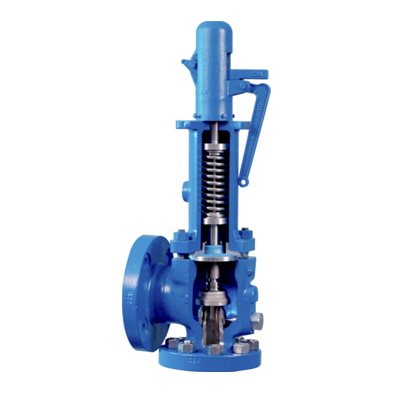
The entire HSL range of F thru Q orifices uses
a full nozzle design (Figure 1) to facilitate
removal and ease of maintenance compared
to semi-nozzle designs.
Details of the HSL valve design, materials of
construction, pressure-temperature ratings
and dimensions are provided in Crosby
technical datasheet VCTDS-00595.
2 SPARE PARTS
Emerson recommends spare parts as shown
on Figures 1 and 2. When ordering spare parts,
the valve size, style and serial number should
be given together with set pressure, part name,
and reference number from Figure 1 or 2.
Spare parts may be ordered from any Emerson
regional sales office or authorized Emerson
sales representative.
© 2017 Emerson. All Rights Reserved.
Engineering doc. nr.: IS V3187
VCIOM-03104-EN 22/03
Advertisement

Related Manuals for Emerson CROSBY


Summary of Contents for Emerson CROSBY
- Page 1 1 INTRODUCTION Details of the HSL valve design, materials of construction, pressure-temperature ratings Crosby Style HSL is a full nozzle reaction and dimensions are provided in Crosby type safety valve designed for saturated and technical datasheet VCTDS-00595.
- Page 2 CROSBY STYLE HSL SAFETY VALVES INSTALLATION, MAINTENANCE AND ADJUSTMENT INSTRUCTIONS BILL OF MATERIALS (F thru J Orifice) FIGURE 1 Item Part name Material Body ASME SA216 Grade WCB/WCC Carbon steel (HSL-( )6) ASME SA217 Grade WC6 Chrome Moly steel (HSL-( )8)
- Page 3 CROSBY STYLE HSL SAFETY VALVES INSTALLATION, MAINTENANCE AND ADJUSTMENT INSTRUCTIONS BILL OF MATERIALS (K thru Q Orifice) FIGURE 2 Item Part name Material Body ASME SA216 Grade WCB/WCC Carbon steel (HSL-( )6) ASME SA217 Grade WC6 Chrome Moly steel (HSL-( )8)
- Page 4 The seals protecting the spring setting The user is advised to contact Emerson or its and ring adjustments should be intact. If seals authorized assemblers and representatives for...
- Page 5 Cap Top Plug Gasket Spindle Seal CROSBY STYLE HSL SAFETY VALVES Wire INSTALLATION, MAINTENANCE AND ADJUSTMENT INSTRUCTIONS Threaded Cap Cap and Test Rod Type A Type B - Threaded Cap Type E - Packed Lifting Lever FIGURE 3 FIGURE 4...
- Page 6 Set pressure adjustment information specific to the type and size valve being Set pressure adjustment should not be tested. Contact your local Emerson sales or service necessary on a new valve but if the valve is office for this information.
- Page 7 IMPORTANT system before dismantling. There should be no interchangeable between ends of the spring. Crosby Style HSL valves have the factory ring system pressure when a valve is dismantled in G. The disc holder assembly or disc and settings stamped on the machined surface on place or removed for shop repair.
- Page 8 In the following sections you find information L. Unscrew the nozzle from the body (the on lapping techniques, tools and materials. Crosby Style HSL utilizes a removable full Lapping blocks are made of a special grade of nozzle design). annealed cast iron (see Figure 6). There is a block for each orifice size.
- Page 9 E. Apply polish compound to another block and as shown in Figure 5. Machining dimensions for Crosby Style HSL valves are shown in Table 2 lap the seat. F. As the lapping nears completion, only the and Figure 5.
- Page 10 Do not force the spindle to thread into the disc. Reference Valve Design Version and Interchangeability Section for more detail on the design version numbers, and contact Emerson to get the correct disc and spindle.
- Page 11 VCIOM-03104-EN © 2018, 2022 Emerson Electric Co. All rights reserved 03/22. Crosby is a mark owned by one of the companies in the Emerson Automation Solutions business unit of Emerson Electric Co. The Emerson logo is a trademark and service mark of Emerson Electric Co. All other marks are the property of their prospective owners.