Advertisement
Quick Links
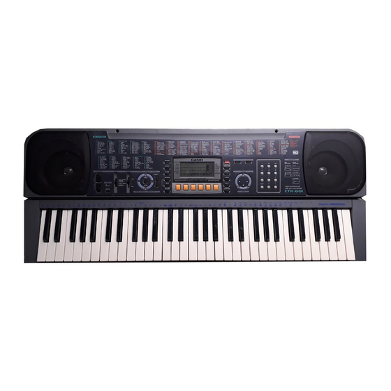
CTK-601
100 RHYTHMS
PITCH BEND
MODE
VOLUME
INTRO
SYNCHRO/ENDING
TEMPO
START
MAX
FULL RANGE
CHORD
FINGERED
POWER
CASIO CHORD
NORMAL
STOP
MIN
NORMAL/FILL-IN
VAR/FILL-IN
ELECTRONIC KEYBOARD
REVERB
DEMO
RHYTHM
REVERB
HALL
GM
TRANSPOSE/
STAGE
SYNTH
FREE
TUNE/MIDI
ROOM
SESSION
SYNTH
LAYER
MIXER
SPLIT
MEMORY
FREE
MIXER
TOUCH
STEP
SESSION
RESPONSE
MEMORY
LAYER
MEMORY TRACK/DRUM PAD
CHORD/1
2
3
4
5
6
STEP
SPLIT
ACCOMP
TOUCH
RESPONSE
VOLUME
200 TONES
TONE
ENVELOPE
AMP
PITCH
ENVELOPE
ENVELOPE
000-048 DECAY
00 FLAT
CURSOR
049-137 SUSTAIN 01-19 VIBRATO
20-49 OTHERS
DIGITAL REVERB SYSTEM
2WAY MULTI-TRACK MEMORY
ENTER
CTK-601
Advertisement

Related Manuals for Casio CTK-601


Summary of Contents for Casio CTK-601
- Page 1 CTK-601 100 RHYTHMS 200 TONES REVERB DEMO RHYTHM TONE ENVELOPE REVERB PITCH HALL ENVELOPE ENVELOPE TRANSPOSE/ STAGE SYNTH FREE TUNE/MIDI 000-048 DECAY 00 FLAT ROOM SESSION SYNTH LAYER MIXER SPLIT MEMORY FREE PITCH BEND MODE VOLUME INTRO SYNCHRO/ENDING MIXER TOUCH...
-
Page 2: Table Of Contents
3 reverb types (HALL, STAGE, ROOM) Auto accompaniment Rhythm patterns: Tempo: Variable (216 steps, = 40 to 255) Chords: 3 fingering methods (CASIO CHORD, FINGERED, FULL RANGE CHORD) Rhythm controller: START/STOP, INTRO, NORMA/FILL-IN, VAR/FILL-IN, SYNCHRO/END- Accomp volume: 0 to 127 (128 steps) - Page 3 Terminals MIDI terminals: IN, OUT Assignable terminal: Standard jack (sustain, sostenuto, soft, rhythm start/stop) Headphone/Output terminal: Stereo standard jack Output Impedance: 120 Ω Output Voltage: 4.5 V (RMS) MAX Power supply terminal: 9 V DC Power supply Dual power supply system Batteries: Six D-size batteries Battery life:...
-
Page 4: Block Diagram
BLOCK DIAGRAM SEG1 ~ SEG40 Working Storage LCD Driver RAM (256K-bit) MIDI LSI4 P10, P13 LSI401 TC55257DFL-70L(EL) P14, P17 SED1278F0A COM1 ~ COM16 Reset IC RESET RN5VD40AA FI0 ~ FI9 MA14 SI0 ~ SI9 Keyboard Sound Source ROM MD0 ~ MD15 LSI1 (16M-bit) KC0 ~ KC7... -
Page 5: Circuit Description
CIRCUIT DESCRIPTION KEY MATRIX C2 (1) C#2 (1) D2 (1) D#2 (1) E2 (1) F2 (1) F#2 (1) G2 (1) C2 (2) C#2 (2) D2 (2) D#2 (2( E2 (2) F2 (2) F#2 (2) G2 (2) G#2 (1) A2 (1) A#2 (1) B2 (1) C3 (1) - Page 6 Note: Each key has two contacts, the first conatct (1) and second contact (2). First contact (1) Second contact (2) NOMENCLATURE OF KEYS F#3 G#3 A#3 C#4 D#4 F#4 G#4 A#4 C#5 D#5 F#5 G#5 A#5 C2 D2 G2 A2 C3 D3 G3 A3 B3 C4...
- Page 7 CPU (LSI1: UPD913GF-3BA) The 16-bit CPU contains a 1k-byte RAM, three 8-bit I/O ports, two timers, a key controller and serial interfaces. The CPU detects key velocity by counting the time between first-key input signal FI and second-key SI from the keyboard.
- Page 8 DIGITAL SIGNAL PROCESSOR (LSI2: HG51B227FB-1) The DSP receives 16-bit serial sound data output from the CPU and adds the selected effect to the sound data using the effect RAM. Then the DSP provides the sound data to the DAC. The DSP also controls button input/ output.
- Page 9 Pin No. Terminal In/Out Function EOEB Read enable signal output for the effect RAM VSS3 Ground(0V) source EWEB Write enable signal output for the effect RAM 62,66,70,74,78 VSS2 Ground source 63,67,71,75,79 VDD2 +5 V source 64,65,68,69, PA0~PA5 Button scan signal output 72,73 76,77 PA6/7...
- Page 10 DAC (LSI6: UPD6379GR) The DAC receives 16-bit serial data output from the DSP. The data contains digital sound data of the melody, chord, bass, and percussion for the right and left channels. The DAC converts the data into analog waveforms and output them to each channel separately. Synch signal SCK1 SINC...
- Page 11 POWER AMPLIFIER (IC101: TA8248K) The power amplifier is a two-channel amplifier with standby switch. The following table shows the pin function of IC101. — — t i c — t i c , f f — n i l t i c v i t v i t —...
-
Page 12: Adjustment
ADJUSTMENT DISPLAY PCB 1) Items to be adjusted: 2) Adjustment and Test Point Locations (TOP VIEW) VR410 3) Equipment connection/Procedure Vop voltage setting Voltmeter Output Input Input Input Output Output Adjust for Adjust Connection Point Signal Connection Point Adjust for 4.4 ± 0.1 V reading VR410 Voltmeter on voltmeter. -
Page 13: Major Waveforms
MAJOR WAVEFORMS 0.5 s 20 ms 1 ms 1 ms Power button ON – – – – ˜ ˜ ˜ ˜ CH1: 5 V CH2: 5 V CH1: 5 V CH2: 5 V CH1: 50 mV CH2: 50 mV CH1: 50 mV CH2: 50 mV 1 NMI signal 3 Button scan signal PA0... -
Page 14: Printed Circuit Boards
PRINTED CIRCUIT BOARDS Sub PCB JCM462-MA2M Top View Main PCB JCM462-MA1M Top View Bottom View — 13 —... -
Page 15: Schematic Diagrams
SCHEMATIC DIAGRAMS Main PCB JCM462-MA1M — 14 —... - Page 16 Sub PCB JCM462-MA2M/Volume PCB JCM462-MA3M — 15 —...
- Page 17 Display PCB JCM462-LCD1M — 16 —...
- Page 18 Keyboard PCBs JCM617T-KY1M/KY2M — 17 —...
- Page 19 Common Segment — 18 —...
-
Page 20: Exploded View
EXPLODED VIEW — 19 —... -
Page 21: Parts List
PARTS LIST CTK-601 Notes: This parts list does not include the cosmetic parts, which parts are marked with item No. "R-X" in the exploded view. Contact our spare parts department if you need these parts for refurbish. Prices and specifications are subject to change with- out prior notice. - Page 22 Item Code No. Parts Name Specification Main PCB 6925 8440 Main PCB ass'y, M462-MA1M M240613*1 LSI1 2012 4879 LSI, CPU UPD913GF-3BA(T) LSI2 2012 2079 LSI, DSP HG51B277FB-1 LSI3 2012 5590 LSI, ROM UPD23C16000WGX-C51 LSI4/LSI5 2012 5572 LSI, RAM TC55257DFL-70L(EL) LSI6 2105 4746 LSI, DAC UPD6379GR-E1 2012 1883 IC...
- Page 23 Item Code No. Parts Name Specification 6925 8680 Rubber button 462G M240548-1 6913 6410 Slide contact 12D CSB-12D 6921 5030 Slide knob M311859-1 6925 8580 Display plate M240568-1 6906 8456 Battery cover M311164F*12 Accessory 6925 8690 Music stand M340629*1 — 21 —...
- Page 24 MA0400571A...