Table of Contents
Advertisement
Quick Links
Installation and Maintenance Manual
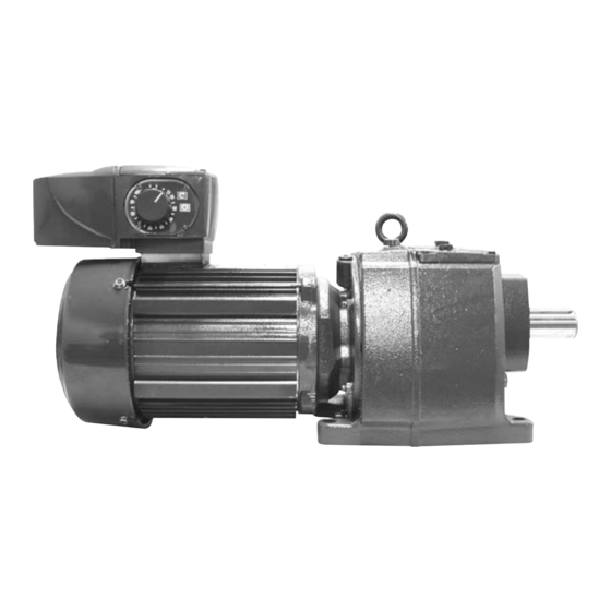
For IntelliGear Plus™ Variable Speed
Gearmotors and Motors
• Read and follow all instructions carefully.
• Disconnect and lock-out power before installation and maintenance.
Working on or near energized equipment can result in severe injury or death.
• Do not operate equipment without guards in place. Exposed equipment can
result in severe injury or death.
• Avoid contact with energized circuits or rotating parts.
• High voltage and rotating parts can cause serious or fatal injury.
c e
®
c
us
UL Listed
E211799
Ind. Cont EQ. 54 DN
Power Transmission Solutions
Regal Beloit America, Inc.
7120 New Buffington Road
Florence, KY 41042
Application Engineering: 800 626 2093
www.RegalPTS.com
• Periodic inspections should be performed. Failure to perform proper maintenance
can result in premature product failure and personal injury.
• Avoid contact with capacitors until safe discharge procedures have been
completed.
• All electrical work should be performed by qualified personnel and be compliant
with local and national electrical codes.
• Be sure shaft key is fully captive before unit is energized.
• Most units are shipped with oil. Always be sure oil lubricated units
are filled with correct oil to proper level before operating.
• Avoid extended exposure to equipment with high noise levels.
F O R M
9112E
Revised
October 2015
Advertisement
Table of Contents

Summary of Contents for Browning IntelliGear Plus
- Page 1 Regal Beloit America, Inc. 9112E 7120 New Buffington Road Installation and Maintenance Manual Florence, KY 41042 Revised For IntelliGear Plus™ Variable Speed Application Engineering: 800 626 2093 October 2015 www.RegalPTS.com Gearmotors and Motors • Read and follow all instructions carefully.
- Page 2 Thank you for choosing an IntelliGear Plus Gearmotor. • Read and follow all instructions carefully. • Disconnect and lock-out power before installation and maintenance. Working on or near energized equipment can result in severe injury or death. • Avoid contact with energized circuits or rotating parts.
- Page 3 For further information, consult the manual. IntelliGear Plus motors contain parts which are sensitive to static electricity and may be easily damaged if handled incorrectly. All work relating to transportation, installation and maintenance...
-
Page 4: Table Of Contents
IntelliGear Plus Variable Speed Gearmotors and Motors Contents General Information ..................................3 General operating principle ................................5 Product name ....................................5 Characteristics ..................................6 - 7 Environmental characteristics ................................7 Radio-frequency interference ................................8 1.5.1 General ......................................8 1.5.2 Standards (Emissions) ...................................8 1.5.3 Standards (Immunity) ..................................8 Description of cables and protection devices (Customer Supplied) ..................8 - 9 UL conformity ....................................9... -
Page 5: General Information
In the standard product version, the integrated drive does not require any connection other than the power supply. The options may be used to broaden the application range of the IntelliGear Plus. Based on the advanced technology of the IGBT power module, very high efficiency and reduced noise levels are achieved. -
Page 6: Characteristics
IntelliGear Plus Variable Speed Gearmotors and Motors 1.3 - Characteristics 1.3.1 - Electrical Data Single phase design Power supply 115 V ± 10%, 50 - 60 Hz 230 V ± 10%, 50 - 60 Hz Output voltage From input voltage down to (input voltage/speed range) Power range 0.33, 0.50, 0.75 HP... -
Page 7: Environmental Characteristics
- Short circuit on 0 - 10V/24V inputs or outputs Drive reset - By switching off the IntelliGear Plus or by opening/closing the connection between the 24V and ENA (size 31 and 32) terminals, or SDI1 and SDI 2 (size 33) 1.4 - Environmental Characteristics... -
Page 8: Radio-Frequency Interference
The maximum emission level is set by the generic industrial (EN 50081-2) and domestic (EN 50081-1) standards. Variable speed drives use high-speed switches (transistors, IntelliGear Plus conforms to the following standards: semi-conductors) which switch high voltages (around 660V for 3-phase drives) at high frequencies (several kHz). This •... -
Page 9: Ul Conformity
IntelliGear Plus Variable Speed Gearmotors and Motors 1.6 - Description of cables and protection devices (Customer Supplied) cont'd. 230V Three Phase Power Supply 460V Three Phase Power Supply Motor hp Motor hp IntelliGear Plus Input "ire Fuse IntelliGear Plus Input... -
Page 10: Weights And Dimensions
IntelliGear Plus Variable Speed Gearmotors and Motors 1.8 - Weights and dimensions - Gearmotors Dimension (inches) Drive Motor IntelliGear Plus Added Frame Drive Size Weight (lb.) 31 or 31M 6.91 6.45 5.91 4.97 4.81 2.25 2.95 0.62 0.55 8.53 7.61 6.91... -
Page 11: Installation
Clear any condensation from the drain holes at the bottom of the motor. 2.1 - General The IntelliGear Plus is usually fitted to the gear and mounted to the machine with flange or foot mounting. The motor fan cools the whole assembly. Make sure that 3. -
Page 12: Connections
• The IntelliGear Plus has a positive logic configuration. Using shocks. The drive stop function does not protect against a drive with a control system which has a different control these high voltages. - Page 13 IntelliGear Plus Variable Speed Gearmotors and Motors 3.2 - Control Terminal Blocks (Continued) Terminal Number IntelliGear Frame Designation Function Characteristics 31 or 32 +10V analog internal source Accuracy ± 2% Maximum output current 30 mA Voltage input Full scale voltage 10 V ±...
- Page 14 IntelliGear Plus Variable Speed Gearmotors and Motors 3.2 - Control Terminal Blocks (cont'd.) Terminal Number IntelliGear Frame Designation Function Characteristics 31 or 32 Characteristics Analog voltage (common Mode) or uni-directional Voltage input Full scale voltage 10 V ± 2% Input impedance 95 kΩ...
-
Page 15: Power Terminal Blocks
RFI filter is not used in an For the 31 or 32, it is also used to connect a IntelliGear Plus. Otherwise, the RFI filter output fieldbus or the PD digital pad option. is screwed onto this connector and the power supply should be attached to the terminals located 3.4.2... -
Page 16: Wiring Diagrams Based On The Standard Configuration
IntelliGear Plus Variable Speed Gearmotors and Motors Wiring Diagrams 3.5.1 Standard configuration connection diagram Note: For single-phase versions, the power supply is connected to terminals L and N. MCIM15100E • Form 9112E • Printed in USA... -
Page 17: Power Supply And Control For Fcr Brakemotors
ESFR connection card. This connection is made at the factory. - The rectifier is supplied by two mains phases. - The brake is controlled according to the sequence which can be adjusted using the IntelliGear Plus parameters. 3.6.2 Separate power supply... -
Page 18: Commissioning
IntelliGear Plus Variable Speed Gearmotors and Motors Commissioning Setting the speed * Before switching on the IntelliGear Plus 4.1.1 External reference (R option) unit, check that the elctrical connections Adjust the speed reference using the desired are correct, and that any moving parts reference of either 0-10 V or 4-20 mA are mechanically guarded. -
Page 19: Faults - Diagnostics
Variable Speed Gearmotors and Motors Faults - Diagnostics Information relating to the status of the IntelliGear Plus is provided by two indicator lamps located on the control options P1, P2 or P3 or by the internal LED in 31/32. Color and state of... -
Page 20: Speed Control Knob Option (P3)
External resistors with greater continuous power rating can be used, provided that the minimum ohmic value is maintained. Browning, IntelliGear, Intelligear Plus are trademarks of Regal Beloit Corporation or one of its affiliated companies. UL is believed to be a registered trade name and/or trademark of Underwriters Laboratories, Inc. and is NOT owned or controlled by Regal Beloit America Inc.