Advertisement
Quick Links
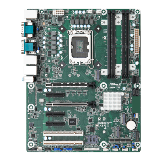
IMB-1712
The terms HDMI
®
and HDMI High-Definition
Multimedia Interface, and the HDMI logo are
trademarks or registered trademarks of HDMI
Licensing LLC in the United States and other
countries.
Revision History
Date
Description
July 5, 2022
First Release
Chassis FAN Connectors (+12V)
1 : CHA_FAN1
FAN_SPEED_CONTROL
9 : CHA_FAN2
CHA_FAN_SPEED
+12V
GND
3 : CHA_FAN3
FAN_SPEED_CONTROL
CHA_FAN_SPEED
+12V
2 : ATX 12V Power Connector
4 : CPU FAN Connector (+12V)
GND
+12V
CPU_FAN_SPEED
FAN_SPEED_CONTROL
5 : PWR LOSS Jumper (PWR_LOSS1)
Short : Power Loss
Open : no Power Loss
6 : 24-pin ATX Power Input Connector
12
24
1
13
7 : M.2 Key-M Socket (M2_M1)
Jumpers and Headers Setting Guide
8 : SATA3 Connectors (SATA3_0 ~ SATA3_3)
10 : Clear CMOS Header (CLRMOS1)
1-2 : Normal
2-3 : Clear CMOS
11 : M.2 Key-B Socket (M2_B1)
GND
8
5
4
1
12 : M.2 Key-E Socket (M2_E1)
13 : 3-pin Thunderbolt AIC Connector (TB2)
Signal
Signal
Signal
PIN
PIN
PIN
Name
Name
Name
TBT_
TBT_
TBT_
1
RTD3_
2
RTD3_
3
RTD3_
RESET#
PWR_EN
WAKE#
14 : 5-pin Thunderbolt AIC Connector (TB1)
Signal
Signal
Signal
PIN
PIN
PIN
1
Name
Name
Name
TBT_
5
GND
4
SLP_S5_
3
S4#
15 : USB 3.2 Gen1 Header
(USB3_5_6)
IntA_P0_SSRX-
IntA_P0_SSRX+
IntA_P0_SSTX-
IntA_P0_SSTX+
IntA_P0_D-
16 : DACC1
IntA_P0_D+
Short : ACC
Open : no ACC
* Auto clear CMOS when system boot improperly.
17 : ATX/AT Mode Jumper (SIO_AT1)
Open : ATX Mode
Short : AT Mode
COM Port Pin9 PWR Setting Jumpers
18 : PWR_COM3 (For COM Port3)
PWR_COM4 (For COM Port4)
PWR_COM5 (For COM Port5)
PWR_COM6 (For COM Port6)
34 : PWR_COM1 (For COM Port1)
PWR_COM2 (For COM Port2)
1-2 : +5V
2-3 : +12V
19 : COM Port Headers (COM3~6) (RS232)
20 : Clear CMOS Header (CLRMOS2)
Open : Normal
Short : Auto Clear CMOS (Power Off)
Signal
Signal
PIN
PIN
Name
Name
TBCIO_
TB_
SLP_
PLUG_
2
1
FRC_
S3#
EVENT_
PWR
R2
Vbus
Vbus
Vbus
IntA_P1_SSRX-
IntA_P1_SSRX+
GND
IntA_P1_SSTX-
GND
IntA_P1_SSTX+
GND
GND
IntA_P1_D-
IntA_P1_D+
ID
1
Advertisement

Related Manuals for ASROCK IMB-1712


Summary of Contents for ASROCK IMB-1712
- Page 1 Jumpers and Headers Setting Guide IMB-1712 The terms HDMI ® and HDMI High-Definition Multimedia Interface, and the HDMI logo are trademarks or registered trademarks of HDMI Licensing LLC in the United States and other countries. Revision History Date Description July 5, 2022...
- Page 2 Installation of ROM Socket * Do not apply force to the actuator cover after ic inserted. * Do not apply force to actuator cover when it is opening over 120 degree, Otherwise, the actuator cover may be broken. * The yellow dot (Pin1) on the ROM must be installed at pin1 position of the socket (white arrow area).