Table of Contents
Advertisement
Quick Links
Advertisement
Table of Contents

Related Manuals for AGFA DR 18M


Summary of Contents for AGFA DR 18M
- Page 1 DR 18M, DR 24M 5400/527 5400/528 User Manual 0380A EN 20180703 1429...
-
Page 2: Table Of Contents
| DR 18M, DR 24M | Contents Contents Legal Notice ................4 Introduction to this Manual ........... 5 Scope .................6 About the safety notices in this document ....7 Disclaimer ..............8 Introduction to the DR Detector ..........9 Intended Use ............10... - Page 3 DR 18M, DR 24M | Contents | iii Environmental protection ........44 Safety Directions ............45 Getting started ..............48 Handling the DR detector ........49 Starting the DR detector .......... 50 Basic Workflow DR Detector ........51 Step 1: retrieve the patient info ....52...
-
Page 4: Legal Notice
Agfa and the Agfa rhombus are trademarks of Agfa-Gevaert N.V., Belgium or its affiliates. DR 18M and DR 24M are trademarks of Agfa NV, Belgium or one of its affiliates. All other trademarks are held by their respective owners and are used in an editorial fashion with no intention of infringement. -
Page 5: Introduction To This Manual
DR 18M, DR 24M | Introduction to this Manual | 5 Introduction to this Manual Topics: • Scope • About the safety notices in this document • Disclaimer 0380A EN 20180703 1429... -
Page 6: Scope
6 | DR 18M, DR 24M | Introduction to this Manual Scope This manual contains information for the safe and effective operation of the DR 18M and DR 24M DR Detectors and peripheral equipment, further referred to as the DR detector. -
Page 7: About The Safety Notices In This Document
DR 18M, DR 24M | Introduction to this Manual | 7 About the safety notices in this document The following samples show how warnings, cautions, instructions and notes appear in this document. The text explains their intended use. DANGER: A danger safety notice indicates a hazardous situation of direct, immediate danger for a potential serious injury to a user, engineer, patient or any other person. -
Page 8: Disclaimer
8 | DR 18M, DR 24M | Introduction to this Manual Disclaimer Agfa assumes no liability for use of this document if any unauthorized changes to the content or format have been made. Every care has been taken to ensure the accuracy of the information in this document. -
Page 9: Introduction To The Dr Detector
DR 18M, DR 24M | Introduction to the DR Detector | 9 Introduction to the DR Detector Topics: • Intended Use • Indications for Use • Intended User • Configuration • Equipment Classification • Operation Controls • System Documentation •... -
Page 10: Intended Use
DR detectors are designed to be equivalent in size to a conventional film and CR image plate. The DR 18M is the appropriate size for a small bucky of any mammography unit and the DR 24M is the appropriate size for a large bucky of any mammography unit. -
Page 11: Indications For Use
DR 18M, DR 24M | Introduction to the DR Detector | 11 Indications for Use The DX-D Retrofit Packages system is indicated for use in specific projection Mammography applications to capture of display diagnostic quality mammography images of human anatomy for adult examinations. The DX-D Retrofit Packages system converts the screen-film or CR Mammography system into a DR Mammography system. -
Page 12: Intended User
12 | DR 18M, DR 24M | Introduction to the DR Detector Intended User This manual is written for trained users of Agfa products. Users are considered as the persons who actually handle the equipment as well as the persons having authority over the equipment. -
Page 13: Configuration
DR 18M, DR 24M | Introduction to the DR Detector | 13 Configuration The DR Detector is a component that can be integrated in an X-ray system and that communicates to a workstation. A workstation can communicate to a single DR Detector. A DR Detector can communicate to a single workstation. -
Page 14: Equipment Classification
14 | DR 18M, DR 24M | Introduction to the DR Detector Equipment Classification Per EN/IEC60601-1, Medical Electrical Equipment, General Requirements for Safety 3rd Edition, this device is classified as following: Table 1: Equipment classification Class I equipment Equipment in which protection against electric... -
Page 15: Operation Controls
DR 18M, DR 24M | Introduction to the DR Detector | 15 Operation Controls Topics: • DR 18M, DR 24M • DR Detector Switch on the NX Workstation • DR detector cable and control unit 0380A EN 20180703 1429... -
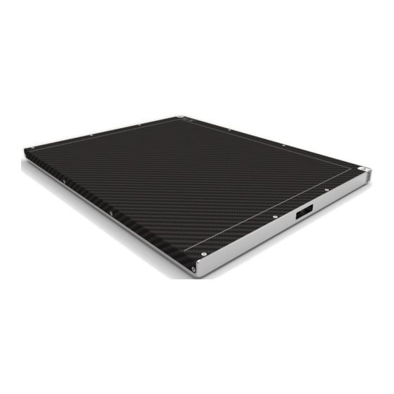
Page 16: Dr 18M, Dr 24M
16 | DR 18M, DR 24M | Introduction to the DR Detector DR 18M, DR 24M Effective imaging area border and center position indication Chest wall Shock indicator DR Detector cable connector Figure 1: DR Detector operation controls... -
Page 17: Dr Detector Switch On The Nx Workstation
DR 18M, DR 24M | Introduction to the DR Detector | 17 DR Detector Switch on the NX Workstation The DR Detector Switch is available in the title bar of the NX application. The DR Detector Switch shows which DR Detector is active and shows its status. -
Page 18: Dr Detector Cable And Control Unit
18 | DR 18M, DR 24M | Introduction to the DR Detector DR detector cable and control unit The DR detector cable connects the DR detector to the DR Detector control unit. The DR detector control unit connects the DR detector to the mains power using a power supply and to the workstation. - Page 19 DR 18M, DR 24M | Introduction to the DR Detector | 19 Related Links Non-medical equipment on page 14 0380A EN 20180703 1429...
-
Page 20: System Documentation
20 | DR 18M, DR 24M | Introduction to the DR Detector System Documentation The documentation shall be kept with the system for easy reference. The most extensive configuration is described within this manual, including the maximum number of options and accessories. Not every function, option or accessory described may have been purchased or licensed on a particular piece of equipment. -
Page 21: Training
DR 18M, DR 24M | Introduction to the DR Detector | 21 Training The user must have received adequate training on the safe and effective use of the system before attempting to work with it. Training requirements may vary from country to country. The user must make sure that training is received in accordance with local laws or regulations that have the force of law. -
Page 22: Product Complaints
22 | DR 18M, DR 24M | Introduction to the DR Detector Product Complaints Any health care professional (for example a customer or a user) who has any complaints or has experienced any dissatisfaction with the quality, durability, reliability, safety, effectiveness, or performance of this product must notify Agfa. -
Page 23: Compatibility
DR 18M, DR 24M | Introduction to the DR Detector | 23 Compatibility The system must only be used in combination with other equipment or components if these are expressly recognized by Agfa as compatible. A list of such equipment and components is available from Agfa service on request. -
Page 24: Compliance
24 | DR 18M, DR 24M | Introduction to the DR Detector Compliance Topics: • General • Safety • Electromagnetic Compatibility • X-ray devices 0380A EN 20180703 1429... -
Page 25: General
DR 18M, DR 24M | Introduction to the DR Detector | 25 General • The product has been designed in accordance with the MEDDEV Guidelines relating to the application of Medical Devices and have been tested as part of the conformity assessment procedures required by... -
Page 26: Connectivity
26 | DR 18M, DR 24M | Introduction to the DR Detector Connectivity Wired communication The use of accessories and cables other than those specified or sold by the manufacturer as replacement parts, may result in increased radiation emissions or decreased stability of the equipment. -
Page 27: Installation
DR 18M, DR 24M | Introduction to the DR Detector | 27 Installation Installation and configuration is performed by an Agfa trained and authorized service engineer. Contact your local support organization for more information. The unit shall not be installed in wet environments like emergency operation rooms and operating theatre. -
Page 28: Messages
28 | DR 18M, DR 24M | Introduction to the DR Detector Messages Under certain conditions the DR Detector shows a dialog box containing a message in the middle of the screen of the NX workstation. This message informs the user that either a problem has occurred or that a requested action cannot be performed. -
Page 29: Labels
DR 18M, DR 24M | Introduction to the DR Detector | 29 Labels Symbol Explanation Operating temperature range: Exposure to temperatures outside the recommended range may damage the equipment or affect performance. Fragile. Handle with care. Special cleaning instructions Do not immerse in liquids No serviceable component inside. - Page 30 30 | DR 18M, DR 24M | Introduction to the DR Detector Symbol Explanation Date of manufacture Serial number This mark shows compliance of the equipment with Directive 93/42/EEC (for European Union). This symbol on the products, and/or accompanying documents means that used electrical and electronic products should not be treated as, or mixed with general household waste.
-
Page 31: Additional Labeling Of The Dr Detector
DR 18M, DR 24M | Introduction to the DR Detector | 31 Additional Labeling of the DR detector Type label on the back side of the DR detector. Figure 5: Example of type label Warranty sealing label Do not to press the detector surface or carry the panel gripping the surface. -
Page 32: Additional Labeling Of The Dr Detector Control Unit
32 | DR 18M, DR 24M | Introduction to the DR Detector Additional Labeling of the DR detector control unit Type label on the bottom side of the control unit. Figure 6: Example of type label 0380A EN 20180703 1429... -
Page 33: Cleaning And Disinfecting
DR 18M, DR 24M | Introduction to the DR Detector | 33 Cleaning and Disinfecting All appropriate policies and procedures should be followed to avoid contamination of the staff, patients and equipment. All existing universal precautions should be extended to avoid potential contaminations and to avoid patients coming into (close) contact with the device. -
Page 34: Cleaning
34 | DR 18M, DR 24M | Introduction to the DR Detector Cleaning To clean the exterior of the equipment: 1. Stop the system WARNING: When the equipment is going to be cleaned, be sure to turn OFF the power of each device, and to unplug the power cord from the AC outlet. -
Page 35: Disinfecting
DR 18M, DR 24M | Introduction to the DR Detector | 35 Disinfecting To disinfect the device, use only disinfectants approved by Agfa. If you plan to use other disinfectants, approval of Agfa is needed before use, as most disinfectants can damage the device. UV disinfection is also not allowed. -
Page 36: Use Of Protective Plastic Envelope
36 | DR 18M, DR 24M | Introduction to the DR Detector Use of protective plastic envelope WARNING: Liquids ingressing the DR Detector may cause malfunction and contamination. If there is a chance that the detector comes in contact with liquids (bodily fluids, water, parenteral nutrition,...) or in direct contact with patient or... -
Page 37: Approved Disinfectants
Disinfectants based upon quaternary ammonium salt (<1 weight percent) and/or alcohol (<75 weight percent) have been found compatible and can be used on the outer surface of the DR 18M and DR 24M DR detector. WARNING: Use only disinfectants that comply with the allowed disinfection practices in your country. -
Page 38: Safety Directions For Disinfection
38 | DR 18M, DR 24M | Introduction to the DR Detector Safety directions for disinfection WARNING: When the equipment is going to be cleaned, be sure to turn OFF the power of each device, and to unplug the power cord from the AC outlet. - Page 39 DR 18M, DR 24M | Introduction to the DR Detector | 39 WARNING: Consult the manufacturer’s Material Safety Data Sheets (MSDS) and recommendations on the product label for additional information prior to use. Disclaimer. The selection and description of the appropriate disinfection procedure and policy is the responsibility of the user.
-
Page 40: Maintenance
40 | DR 18M, DR 24M | Introduction to the DR Detector Maintenance Always consult the Agfa Service documentation and an Agfa trained and authorized service engineer for complete maintenance schedules. In order to ensure that the equipment is used safely and normally, be sure to inspect the equipment before use. -
Page 41: Daily Inspection
DR 18M, DR 24M | Introduction to the DR Detector | 41 Daily inspection As requested by the local procedures for mammography and Organisation for Quality Control for mammography, check the equipment on a regular basis to be sure that workflow and image quality can be guaranteed. -
Page 42: Half-Yearly Inspection
42 | DR 18M, DR 24M | Introduction to the DR Detector Half-yearly inspection To indicate when the half-yearly calibration is due, a message is displayed on the NX workstation. Perform calibration half-yearly or when exposure conditions have changed significantly. For details, refer to the DX-D DR Detector Calibration Key User Manual (0134). -
Page 43: Patient Data Security
DR 18M, DR 24M | Introduction to the DR Detector | 43 Patient data security The user must ensure that the patients’ legal requirements are met and that the security of the patient data is guarded. The user must define who can access patient data in which situations. -
Page 44: Environmental Protection
44 | DR 18M, DR 24M | Introduction to the DR Detector Environmental protection Figure 7: WEEE symbol WEEE end user notice The directive on Waste Electrical and Electronic Equipment (WEEE) aims to prevent the generation of electric and electronic waste and to promote the reuse, recycling and other forms of recovery. -
Page 45: Safety Directions
DR 18M, DR 24M | Introduction to the DR Detector | 45 Safety Directions WARNING: Safety is only guaranteed when an Agfa certified field service engineer has installed the product. WARNING: Improper changes, additions, maintenance or repair of the system can lead to personal injury, electrical shock and damage to the equipment. - Page 46 46 | DR 18M, DR 24M | Introduction to the DR Detector WARNING: The user must not touch part of the X-ray system or electrical input, and patient simultaneously. WARNING: Never disassemble or modify the equipment. Doing so may result in fire or electric shock. Also, since the equipment...
- Page 47 DR 18M, DR 24M | Introduction to the DR Detector | 47 CAUTION: Excessive ambient temperature may impact performance of DR Detectors and cause permanent damage to the equipment. If ambient temperature and humidity is outside the range of 5 - 35 °C and 20 - 75% RH, do not operate the system or use air...
-
Page 48: Getting Started
48 | DR 18M, DR 24M | Getting started Getting started Topics: • Handling the DR detector • Starting the DR detector • Basic Workflow DR Detector • Positioning the DR detector • Manual exposure table for examinations without AEC •... -
Page 49: Handling The Dr Detector
DR 18M, DR 24M | Getting started | 49 Handling the DR detector CAUTION: Observe great care when handling the DR Detector. The detector is shock sensitive and drops should be avoided. Warranty will be void if it is obvious that operating conditions are not met. -
Page 50: Starting The Dr Detector
50 | DR 18M, DR 24M | Getting started Starting the DR detector Note: Before operating the detector, start up the NX workstation. To start the DR Detector: 1. Check if the DR detector cable is connected to the control unit. -
Page 51: Basic Workflow Dr Detector
DR 18M, DR 24M | Getting started | 51 Basic Workflow DR Detector Topics: • Step 1: retrieve the patient info • Step 2: select the exposure • Step 3: prepare the exposure • Step 4: check the exposure settings •... -
Page 52: Step 1: Retrieve The Patient Info
52 | DR 18M, DR 24M | Getting started Step 1: retrieve the patient info At the NX workstation: 1. When a new patient comes in, define the patient info for the exam. 2. Start the exam. Step 2: select the exposure 1. - Page 53 DR 18M, DR 24M | Getting started | 53 Make sure the generator is ready for exposure before you press the exposure button. WARNING: The radiation indicator on the control console lights up during exposure release. WARNING: Do not select another thumbnail until the preview image is visible in the active thumbnail.
-
Page 54: Positioning The Dr Detector
54 | DR 18M, DR 24M | Getting started Positioning the DR detector When performing an exposure, keep in mind the following detector orientation aids: • tube side • chest wall side Figure 8: Detector orientation aids 1. Tube side of the detector 2. -
Page 55: Manual Exposure Table For Examinations Without Aec
DR 18M, DR 24M | Getting started | 55 Manual exposure table for examinations without AEC A manual exposure table containing the exposure settings in function of compressed thickness and breast density can be provided to the user during installation. - Page 56 56 | DR 18M, DR 24M | Getting started mAs values Target/ - 25% target mAs +25% Filter (fatty) (standard) (dense) 90 mm * 75 mm 60 mm 53 mm 45 mm 32 mm 21 mm Figure 10: Template of the manual exposure table that can be attached to the...
-
Page 57: Verifying If An Image Is Exposed Correctly
DR 18M, DR 24M | Getting started | 57 Verifying if an image is exposed correctly On the NX workstation (type 21.00 or higher) an area of the DR mammography image can be selected to measure the pixel value index (PVI). -
Page 58: Special Mammography Views
58 | DR 18M, DR 24M | Getting started Special mammography views Special mammography exams are the magnification views or focal/spot compression views (to make a small area of breast tissue easier to evaluate) that make use of a dedicated bucky. -
Page 59: Automatic Exposure Detection
DR 18M, DR 24M | Getting started | 59 Automatic exposure detection The DR detector detects X-ray exposure to automatically perform the image acquisition. The X-ray system has to generate a minimum exposure dose to trigger the DR detector's automatic exposure detection. -
Page 60: Automatic Exposure Control With Dr 18M
Please be aware that some of the AEC cells may be covered by electronics. The DR 18M detector is not fully compliant with the specifications in ISO 4090 with regard to positioning of the automatic exposure control (AEC) dose- measuring cells in the X-ray modality. -
Page 61: Stopping The Dr Detector
DR 18M, DR 24M | Getting started | 61 Stopping the DR Detector To stop the DR Detector: Power off the DR Detector using the power switch at the front of the control unit. 0380A EN 20180703 1429... -
Page 62: Problem Solving
62 | DR 18M, DR 24M | Problem solving Problem solving Topics: • No image available after exposure • DR image is not displayed • Image shows artifacts 0380A EN 20180703 1429... -
Page 63: No Image Available After Exposure
DR 18M, DR 24M | Problem solving | 63 No image available after exposure Details An exposure is performed and no image becomes available on the NX workstation. Cause 1. Due to the automatic exposure control, the dose may become too low to trigger the DR detector. -
Page 64: Dr Image Is Not Displayed
64 | DR 18M, DR 24M | Problem solving DR image is not displayed Details An image is acquired using a DR detector, but not displayed in the examination. Cause The DR Detector could not send the image directly after the exposure to the NX workstation. -
Page 65: Image Shows Artifacts
DR 18M, DR 24M | Problem solving | 65 Image shows artifacts Details An exposure is performed and the image on the NX workstation shows lines and banding artifacts. Cause The exposure time exceeded the integration time of the DR detector (configured during installation). -
Page 66: Technical Data
66 | DR 18M, DR 24M | Technical Data Technical Data Topics: • DR 18M, DR 24M • DR 18M, DR 24M control unit 0380A EN 20180703 1429... -
Page 67: Dr 18M, Dr 24M
DR 18M, DR 24M | Technical Data | 67 DR 18M, DR 24M Electrical connection DR Detector Rated power supply 12V DC (power over ethernet) 30 W Power consumption Environmental conditions (during normal operation) Room temperature between +5 °C and +35 °C Maximum temperature change rate max. - Page 68 68 | DR 18M, DR 24M | Technical Data Lateral wall distance DR 18M: less than 17.1 mm DR 24M: less than 17.7 mm Shock sensitivity Shock tolerance 40 G Vibration tolerance 1 G, 10~150 Hz Drop tolerance 50 cm...
- Page 69 DR 18M, DR 24M | Technical Data | 69 Minimum Modulation Transfer Function (MTF) 1 lp/mm ≥ 65% 2 lp/mm ≥ 55% 3 lp/mm ≥ 35% 4 lp/mm ≥ 25% 5 lp/mm ≥ 20% 6 lp/mm ≥ 10% 0380A EN 20180703 1429...
-
Page 70: Dr 18M, Dr 24M Control Unit
70 | DR 18M, DR 24M | Technical Data DR 18M, DR 24M control unit Model SSU (System Synchronization Unit) Type 5400/529 Water ingress IPX0 This device does not have protection against ingress of water. Dimensions Dimensions (width x 170.0 mm x 60.5 mm x 170.0 mm height x depth) 1.23 kg... -
Page 71: Remarks For Hf-Emission And Immunity
DR 18M, DR 24M | Remarks for HF-emission and immunity | 71 Remarks for HF-emission and immunity Topics: • EMC (Electromagnetic Compatibility) Statements • Cables, transducers and accessories • Electromagnetic emissions • Electromagnetic immunity 0380A EN 20180703 1429... -
Page 72: Emc (Electromagnetic Compatibility) Statements
72 | DR 18M, DR 24M | Remarks for HF-emission and immunity EMC (Electromagnetic Compatibility) Statements The DR Detector is designed and tested to comply with IEC 60601-1-2(EN60601-1-2) which is applicable to regulations regarding EMC for medical devices and needs to be installed and put into service according to the EMC information stated as follows. -
Page 73: Cables, Transducers And Accessories
DR 18M, DR 24M | Remarks for HF-emission and immunity | 73 Cables, transducers and accessories CAUTION: Using cables and accessories not mentioned in this manual or spare parts not ordered from Agfa, may cause a higher emission of electromagnetic phenomena and/or may rise the susceptibility against it. -
Page 74: Electromagnetic Emissions
74 | DR 18M, DR 24M | Remarks for HF-emission and immunity Electromagnetic emissions This DR Detector has been tested for the electromagnetic environment as described below. The user of the DR Detector should ensure that it is used in such an environment. -
Page 75: Electromagnetic Immunity
DR 18M, DR 24M | Remarks for HF-emission and immunity | 75 Electromagnetic immunity This DR Detector is intended for operation in the electromagnetic environment given below. The user of the DR Detector should ensure that it is used in such an environment. - Page 76 76 | DR 18M, DR 24M | Remarks for HF-emission and immunity < 5% Ur (95% < 5% Ur (95% free of interruptions breakthrough of breakthrough of or a battery. Ur) for 5 s Ur) for 5 s Magnetic field at...
- Page 77 DR 18M, DR 24M | Remarks for HF-emission and immunity | 77 d = 2.3 800 MHz to 2.5 GHz With P as the rated power of the transmitter in watts (W) in accordance with the manufacturer information on the...
- Page 78 78 | DR 18M, DR 24M | Remarks for HF-emission and immunity device must be observed with regard to its normal operation at each place of use. In case of unusual performance characteristics, it can be necessary to take additional measures, such as the re-orientation of the device, for example.