
Related Manuals for Samsung SWL-3000AP Series


Summary of Contents for Samsung SWL-3000AP Series
- Page 1 SWL-3000AP Series Access Point User’s Guide * This User’s Guide can be used on SWL-3000AP, 3000AP(DA), 3300AP and 3300AP(DA).
- Page 2 This Guide is a copyright of : Samsung Electro-Mechanics Co., Ltd. 314 Maetan-3 Dong, Paldal-Gu Suwon, Kyunggi-Do, 442-743 Korea. SWL-3000AP Series Access Point User’s Guide First Edition (November 2001) Models subjected to this User’s Guide : SWL-3000AP, 3000AP(DA), 3300AP, 3300AP(DA) * DA : Dipole Antenna Type...
-
Page 3: Table Of Contents
Table of Contents Introduction Installation AP Basic Setting Using AP Manager PTP Setting Using AP Manager AML Setting Using AP Manager Bridge Table and Protocol Management Using AP Manager NAT Setting Using AP Manager DHCP Server Setting Using AP Manager NAT and DHCP Server Simultaneous Setting Using AP Manager 10. - Page 4 13. Firmware Upgrade Using AP Manager 14. Data Transmission Status Check Using AP Manager 15. AP Setting Using Web Browser 16. AP Setting Using TELNET 17. HyperTerminal Setting for RS-232C(COM Port) Communication 18. AP Basic Setting Using RS-232C(COM Port) 19. Load Default Values Using RS-232C(COM Port) 20.
-
Page 5: Introduction
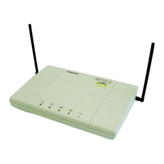
1. Introduction Thank you for purchasing SAMSUNG SWL-3000AP Series Access Point(AP). This guide describes the installation and basic configuration of the Access Point. Standard Model is SWL-3300AP for example. AP Components ! SWL-3000AP Series Access Point ! Wireless LAN Card (Internal for SWL-3300 and 3300(DA) models) - Page 6 ! The Front and Rear View of SWL-3300AP Status Power ! The Front and Rear View of SWL-3300AP(DA) DC in Wireless Ethernet RS-232C RJ-45 Connector...
-
Page 7: Installation
2. Installation ① Choose the place with the consideration of power outlet and network connection (RJ-45 Cable connection) to install the Access Point. ② Plug in the power cord to the power outlet and the power adapter. Plug in the DC output to “DC in”. Make sure that the “Power” LED is on. If the “Power”... - Page 8 ⑩ Through AP, which is installed and set by the method above, you can communicate between server and PC with installed Wireless LAN Card. Ethernet, ADSL, and Cable Modem SWL-3000AP [Models subjected to this User’ s Guide] SWL-3000AP(DA) SWL-3300AP SWL-3300AP(DA)
-
Page 9: Ap Basic Setting Using Ap Manager
3 3 3 3 . AP Basic Setting Using AP Manager ① Execute AP Manager(SWL-3000AP Series, 4000AP Series Management Utility) under MS-Windows 95/98/Me/2000/NT/XP operating system. ② After choosing AP, which will be used by users, on “List Box” of AP Manager using mouse, select [Basic] tab for any changes on setting. - Page 10 ④ TCP/IP address environment is set on [Basic] Dialogue Box. Specify an IP address After consulting with your system administrator, you enter IP Address, Subnet Mask and Gateway Address. Obtain an IP address automatically This setting is possible when AP is used for DHCP Client. ⑤...
- Page 11 Set Channel for AP use. Channel index should be between 1 and 14(differs from country to country). Notice : If you are operating two or more Access Points in the adjoining cells, keep the appropriate channel distance to avoid the interference. We recommend you to keep the distance of at least 4 channels in the adjoining cells.
- Page 12 ⑧ When you click [Confirm & Apply] button to apply new configuration, “Configuration Summary” window, which shows new configuration, will appear. Confirm New Configuration ⑨ If new settings are entered correctly, click [Apply] button to apply new configuration. ⑩ When you click [Apply] button, “Password” window will appear. The default password is “public”, and user can change password later.
- Page 13 ⑪ After you enter the password, click [OK] button. ⑫ If you want to set default values, click [Load Default values] button. Then, AP Configuration will return to default setting. Resetting to Default Values...
-
Page 14: Ptp Setting Using Ap Manager
4. PTP Setting Using AP Manager ① PTP stands for Point to Point, and it is used to connect two divided networks into one using AP as Wireless Bridge. In this case, AP cannot be used for capabilities of Access Point. Internet Network (Hub) <... - Page 15 ③ When Operation Mode of AP is selected for “Point-to-Point” on [Radio] Dialogue Box, [Remote ID (PTP)] Box will appear to enter MAC ID of Wireless LAN Card on other AP, which will be connected by using PTP mode. ④ When [Edit] button on [Remote ID (PTP)] Box is selected, [MAC ID] Box, which is to enter(for entering) MAC ID of Wireless LAN Card of other AP to be connected, will appear.
- Page 16 Confirm MAC ID Setting of other Wireless LAN Card to be connected using PTP Mode ⑤ ESSID and Channel of two APs must be identical in PTP mode ⑥ When you click [Confirm & Apply] button to apply new configuration, “Configuration Summary”...
- Page 17 Confirm Common ESSID and Channel for AML Mode Setting ⑦ If new settings are entered correctly, click [Apply] button to apply new configuration. ⑧ When you click [Apply] button, “Password” window will appear. ⑨ After you enter the password, click [OK] button. ⑩...
- Page 18 new configuration. ⑪ After rebooting, choose selected proper AP on “List Box”. Then, the selected AP set with PTP Mode can be confirmed on [Selected AP’s Info] Group Box as shown below. Confirm PTP Mode Setting...
-
Page 19: Aml Setting Using Ap Manager
5. AML Setting Using AP Manager ① AML stands for Automatic Multi-link. Using AP as Wireless Bridge, it is used to connect several divided networks into one. It connects several [Slave]s with one main [Master]. Internet Network (Hub) <Wire Network using Hub> ②... - Page 20 ④ Select either “Master” or “Slave” for [Control Mode] on [Automatic Multi-link] Box. Basically, AML Mode consists of two or more APs, and set one for “Master” and the rest for “Slave”s. Setting AML Control Mode Default Value for “Monitor Interval”...
- Page 21 ⑤ All of ESSID and Channel of AP set in AML mode must be identical. ⑥ When you click [Confirm & Apply] button to apply new configuration, “Configuration Summary” window, which shows new configuration, will appear. Confirm Common ESSID and Channel for AML Mode Setting ⑦...
- Page 22 ⑨ After you enter the password, click [OK] button. ⑩ When you click [Apply] button instead of [Confirm & Apply] button, “Password” window will appear immediately skipping “Configuration Summary” window. After you enter the password, click [OK] button to apply new configuration.
-
Page 23: Bridge Table And Protocol Management Using
6. Bridge Table and Protocol Management Using AP Manager ① Using AP Manager, list of Wired and Wireless Station(PC or AP) connected to current AP can be confirmed. Also, it sets type of Protocol to receive and send selected data, which satisfy Protocol user wants, among data transmitting through AP. - Page 24 ④ [Age Time] on [Bridge Table] Management Box shows cycle of AP refreshing “Bridge Table”. The use of Default Values is recommended. ⑤ After selecting Station Type you want with Radio button to refresh Stations connected to current AP, click [Refresh Bridge Table] button to confirm. Confirm Refresh Bridge Table Number...
- Page 25 Select “Enabled” ⑩ If new settings are entered correctly, click [Apply] button to apply new configuration. ⑪ When you click [Apply] button, “Password” window will appear. ⑫ After you enter Password, click [OK] button. Select Protocol Which You Do Not Want...
-
Page 26: Nat Setting Using Ap Manager
7. NAT Setting Using AP Manager ① NAT stands for Network Address Translation, and it is used to establish private network domain. Using NAT, any desktop or notebook PC, which are connected to AP, may freely use any private IP Address. In this case, the private IP Address must have same Network Address assigned for NAT IP Address. - Page 27 ③ When you click [Confirm & Apply] button to apply new configuration, “Configuration Summary” window, which shows new configuration, will appear. ④ If new settings are entered correctly, click [Apply] button to apply new configuration. ⑤ When you click [Apply] button, “Password” window will appear. ⑥...
- Page 28 ⑦ When you click [Apply] button instead of [Confirm & Apply] button, “Password” window will appear immediately skipping “Configuration Summary” window. After you enter the password, click [OK] button to apply new configuration. ⑧ After rebooting, choose selected proper AP on “List Box”. Then, the selected AP set with NAT can be confirmed on [Selected AP’s Info] Group Box as shown below.
- Page 29 Select “TCP/IP” [Properties] of LAN Adapter to use on [Configuration] Menu. Set “IP Address” and “Subnet Mask” on [IP Address] Menu. In this case, IP Address entered on “IP Address” must have same Network Address of IP Address of AP assigned for NAT.(Refer step ①.)
- Page 30 Configuration has been completed for desktop or notebook PC to connect with AP. In this case, the specified IP Address of desktop or notebook PC should have same network address as set by NAT setting.(Refer step ①.) Gateway have same as “IP Address” of AP assigned by NAT Setting on “New Gateway”...
-
Page 31: Dhcp Server Setting Using Ap Manager
8. DHCP Server Setting Using AP Manager ① DHCP stands for Dynamic Host Configuration Protocol, it is protocol that enables Network administrator to manage and assign IP Address in system centrally. DHCP manages and assigns IP Address for network administrator, and it enables computer to get assigned IP Address when it is connected to other place in the network. - Page 32 Scope of IP Address Assignable Lease Time for Assigned IP Address Assessed Information with IP Address Notice : When you select DHCP Server, the values on the window show information assigned to DHCP Client with IP Address. In most cases, values of “Gateway”...
- Page 33 ⑤ To set the scope of assignable IP Address, first check on [Empty] check box on the left. Then, “Empty” will be changed to “Valid”, and you can set the scope. ⑥ Enter the beginning value in “From”, and ending value in “To”. ⑦...
- Page 34 ⑪ After you enter the password, click [OK] button. ⑫ When you click [Apply] button instead of [Confirm & Apply] button, “Password” window will appear immediately skipping “Configuration Summary” window. After you enter the password, click [OK] button to apply new configuration.
- Page 35 Notice : If you want to set DHCP Client instead of DHCP Server, select [Basic] on “Tab Bar” menu of AP. Then, select “Obtain an IP address automatically” from Dialogue Box. (Refer to step ④ of Chapter6.) Then, the selected AP gives up its own IP Address, and other AP using DHCP Server will assign it.
-
Page 36: Nat And Dhcp Server Simultaneous Setting Using
9. NAT and DHCP Server Simultaneous Setting Using AP Manager ① After executing AP Manager, select [Server] tab on “Tab Bar” to set DHCP Server and NAT simultaneously. ② Please refer to Chapter 10 for NAT Setting and Chapter 11 for DHCP Server Setting. - Page 37 ③ When you click [Confirm & Apply] button to apply new configuration, “Configuration Summary” window, which shows new configuration, will appear. ④ If new settings are entered correctly, click [Apply] button to apply new configuration. ⑤ When you click [Apply] button, “Password” window will appear. ⑥...
- Page 38 ⑦ When you click [Apply] button instead of [Confirm & Apply] button, “Password” window will appear immediately skipping “Configuration Summary” window. After you enter the password, click [OK] button to apply new configuration. ⑧ After rebooting, choose selected proper AP on “List Box”. Then, the selected AP set with NAT and DHCP Server can be confirmed on [Selected AP’s Info] Group Box as shown below.
-
Page 39: Adsl And Cable Modem Connection Setting Using
10. ADSL and Cable Modem Connection Setting Using AP Manager ① After executing AP Manager, click [Advanced] and [Internet Connection] “Menu Bar” in the following order. Or click [Internet Connection] button on [Basic] Dialogue Box. ② Then the Internet Connection Setup page(default page) will appear. Select your Internet connection service type and click Select on “Menu Bar”... - Page 40 Notice: ADSL can generally be divided into two service types supporting PPPoE or PPTP, but PPPoE is more common. If you don’t know your ADSL service type, please check the Website or contact your ISP to find out service type you are using. ③...
- Page 41 ③ Set NAT and DHCP Server referring Chapter 9. DHCP Server and NAT Setting ④ Click [Finish] button to complete setting.
- Page 42 ⑤ A window will appear and ask you to apply new settings immediately. If you do not want to apply new settings, select [No(N)]. ⑥ If you click [Yes(Y)] button, “Password” window will appear. After you enter the password, click [OK] button to apply. In case you select [No(N)] button, new settings will be saved.
- Page 43 10.2 Settings for ADSL – PPTP ① When the above page appears, enter the user name given by your ISP(Internet Service Provider) in the “User Name” box. ② Enter the password in the “Password” box. ③ Enter the IP Address of PPTP Server in the “PPTP Server IP Address” box Notice: In case IP Address of PPTP Server are unknow, contact your ISP.
- Page 44 ④ Set NAT and DHCP Server referring Chapter 9. Setting DHCP Server and NAT ⑤ Click [Finish] button to complete setting.
- Page 45 ⑥ A window will appear and ask you to apply new settings immediately. If you do not want to apply new settings, select [No(N)]. ⑦ If you click [Yes(Y)] button, “Password” window will appear. After you enter the password, click [OK] button to apply. In case you select [No(N)] button, new settings will be saved.
- Page 46 10.3 Settings for Cable Modem ① Set NAT and DHCP Server referring Chapter 9. Notice : Personal Information Setting is not needed because Cable modems are generally given with fixed IP Address. ② Click [Finish] button to complete setting. Setting DHCP Server and NAT...
- Page 47 ③ A window will appear and ask you to apply new settings immediately. If you do not want to apply new settings, select [No(N)]. ④ If you click [Yes(Y)] button, “Password” window will appear. After you enter the password, click [OK] button to apply. In case you select [No(N)] button, new settings will be saved.
-
Page 48: Encryption Setting Using Ap Manager
11. Encryption Setting Using AP Manager ① After executing AP Manager, select [Security] tab on “Tab Bar” to set encryption. Then, select “Encryption”. ② Select either “64(40)-bit Key” or “128-bit Key.” The window below shows “64(40)-bit Key” setting. Select Encryption ③... - Page 49 ④ Enter the agreed password phrase to set encryption in “Passphrase,” and click [Generate] button to create WEP Key. Enter Password Phrase After generating the keys, select one key among “Default Key”s. Click [OK] button to complete setting of the key to be used for encryption. Notice : In this case, WEP Keys should be generated using same Passphrase for Card Utility of desktop and notebook PC.
- Page 50 Confirm 64(40)-bit Encryption Setting ⑥ If new settings are entered correctly, click [Apply] button to apply new configuration. ⑦ When “Password” window appear, enter the password. Then click [OK] button. ⑧ After rebooting, choose selected proper AP on “List Box”. Then, the selected AP set with Encryption can be confirmed on [Selected AP’s Info] Group Box as shown below.
-
Page 51: User Access Control Setting Using Ap Manager
12. User Access Control Setting Using AP Manager ① “User Access Control” is function that shows permission of using AP to MAC ID Table of Wireless LAN Card installed on certain Stations among desktop or notebook PC, which are connected AP. If you want to use this function, select “User Access Control”... - Page 52 Select Connection Deny Click [+] icon, and enter MAC ID as shown on the window below. Then, click [OK] button to add MAC ID on [Allowed Table].
- Page 53 ⑥ When you want to deny specific MAC ID and permit the other, select “pass” on [Other Stations] Box. Then, add the MAC ID on [Denied Table], which is you want to deny. MAC ID can be entered by the method explained on ⑤ and also move MAC ID from [Allowed Table].
- Page 54 ⑨ If you want to export and save MAC IDs registered either on [Allowed Table] or [Denied Table], click [Export] button. Then, it will be saved where user wants as “granted.lst” or “denied.lst”. You can rename the file name. # granted.lst ->...
- Page 55 ⑩ You can combine and use various settings as you wish. ⑪ If new settings are entered correctly, click [Apply] button to apply new configuration. ⑫ When “Password” window appear, enter the password. Then, click [OK] button.
-
Page 56: Firmware Upgrade Using Ap Manager
13. Firmware Upgrade Using AP Manager ① Whenever the new version of AP Firmware is available, you can upgrade AP firmware into higher version using AP Manager. ② After executing AP Manager, select [Firmware] tab on “Tab Bar”. ③ Dialogue Box of the Firmware upgrade is like what is view in the window below. - Page 57 ⑤ Downloaded the latest version of AP firmware in local disk of your PC Notice: AP firmware corresponding to your AP can be downloaded in MagicLAN home page. ⑥ Click the file icon shown below on Dialogue Box. ⑦ After select the firmware image file, click [Open] button. File Icon...
- Page 58 ⑧ Click the [Load] button after the file is selected. Then, “Password” window will be displayed. ⑨ Enter the password, default password is “public”, and click [OK] button. The AP firmware is loaded from your Local Disk to the Access Point and is upgraded.
-
Page 59: Data Transmission Status Check Using Ap Manager
14. Data Transmission Status Check Using AP Manager ① Data transmission traffic status of current AP can be confirmed using AP Manager. ② When [Statistics] tab on “Tab Bar” of AP Manager is selected, a window, which shows [Traffic Selection] Box on Dialogue Box to select Traffic type and shows related information below, will appear. - Page 60 ⑤ If you want to confirm with line graph, select “Line” instead of “Histogram” on Related Information Confirm Box. ⑥ In this case, if confirm is impossible due to increased number of packets with wired and wireless transmission, increase scope of number of packet transmitted per second(packet/sec) to confirm.
- Page 61 # SNMP : Simple Network Management Protocol # MIB : Management Information Base Select MIB Type Related Information Confirm Box ⑨ Confirming Traffic information you want enables more efficient AP operation.
-
Page 62: Ap Setting Using Web Browser
15. AP Setting Using Web Browser ① Open Web Browser. (Beyond IE 4.0 or Netscape 4.0) ② Enter AP’s IP Address on “Address” of the Web Browser. Press [ENTER : ] key. ③ “Enter Network Password” window appears. Do not enter the User Name. Enter the password. - Page 63 ④ Internet Connection Setting page”(default page) appears. ⑤ Simple Configuration Mode is for Setting of Internet Connection Environment, and refer to “10. ADSL and Cable Modem Connection Setting Using AP Manager”. ⑥ Expert Mode is for Network Administration, and refer to “3. AP Basic Setting Using AP Manager”.
-
Page 64: Ap Setting Using Telnet
16. AP Setting Using TELNET ① Open “Run” on [Start] menu of desktop and notebook PC. Enter the IP Address for Internet Connection as following Example. Example) telnet ***.***.***.*** (IP Address ) Click [OK] button. ② Telnet order window appears, and please refer to “18. AP Basic Setting Using RS-232C(COM Port)”... -
Page 65: Hyperterminal Setting For Rs-232C(Com Port)
HyperTerminal Communication ① Execute the HyperTerminal under MS-Windows 95/98/Me/2000/NT/XP operating system by following the steps below. Execute Hypertrm.exe file in “HyperTerminal” folder. ② After executing the Hypertrm.exe file, the following window will be displayed on MS-Windows. Setting RS-232C(COM Port) - Page 66 ③ As displayed above, type “AP MANAGER” in the name field, and click [OK] button. You can enter any name you wish for the connection. ④ Select the modem port as shown in the window below, and click [OK] button. (In most of the cases, select either “Direct to Com1”...
- Page 67 ⑥ If all the steps above are executed correctly, then the following menu will be displayed on the HyperTerminal window. The default password is “public”, and user can change password later. ================================================== Samsung SWL-3300AP Configuration ================================================== To configure the Access Point, the password is required. Enter password : ⑦...
-
Page 68: Ap Basic Setting Using Rs-232C(Com Port)
18. AP Basic Setting Using RS-232C(COM Port) ① Choose [Basic] menu on [ROOT] menu. ================================================== Samsung SWL-3300AP Configuration ================================================== [ Basic ] 1. ESSID 2. Channel 3. DHCP Client 4. IP Address 5. Subnet Mask 6. Gateway Address 7. Description CMD(t,p,h): ②... - Page 69 ③ Select the following order to change Wireless Channel. CMD(t,p,h): 2 Enter new Channel {1-14}: 11 Enter the proper channel number after the phrase “Enter new Channel {1- 14}:”. Then, press [ENTER : 14(differs from country to country). Notice : If you are operating two or more Access Points in the adjoining cells, keep the appropriate channel distance to avoid the interference.
- Page 70 ⑥ Select the following order to set Subnet Mask. CMD(t,p,h): 5 Enter new Subnet Mask : 255.255.255.0 Enter the proper subnet mask after the phrase “Enter new Subnet Mask :”. Then, press [ENTER : ]. Consult your system administrator for setting the subnet mask. ⑦...
- Page 71 ⑨ If you want to change Password, select the following order on [ROOT] menu. ================================================== Samsung SWL-3300AP Configuration ================================================== [ ROOT ] 1. Basic 2. Advanced 3. Server 4. Status 5. Load default values 6. Save and reboot CMD(t,p,h): 2 Select [Administration] menu on [Advanced] Menu.
- Page 72 ================================================== Samsung SWL-3300AP Configuration ================================================== [ Administration ] 1. Password activity 2. Change password CMD (t,p,h): 2 Enter current password (Max. 30 characters):****** Enter new password (Max. 30 characters):****** Enter new password again:****** Enter the current password (Max. 30 characters) after “Enter current password (Max.
- Page 73 ⑩ You must select “Save and reboot” on [ROOT] menu, after changing the appropriate parameters by entering the new values. ================================================== Samsung SWL-3300AP Configuration ================================================== [ ROOT ] 1. Basic 2. Advanced 3. Server 4. Status 5. Load default values 6.
- Page 74 ⑪ After following all the steps mentioned above, you can close the HyperTerminal window if there is no need for change or setting. Select [Basic] menu if you want to confirm the settings. ================================================== Samsung SWL-3300AP Configuration ================================================== [ Basic ] 1. ESSID 2.
-
Page 75: Load Default Values Using Rs-232C(Com Port)
19. Load default values Using RS-232C(COM Port) ⑫ Select “Load default values” on [ROOT] menu ================================================== Samsung SWL-3300AP Configuration ================================================== [ ROOT ] 1. Basic 2. Advanced 3. Server 4. Status 5. Load default values 6. Save and reboot CMD(t, p, h): 5 All configured items will be set to the default values. -
Page 76: Firmware Upgrade Using Rs-232C(Com Port)
Notice: AP firmware corresponding to your AP can be downloaded in MagicLAN home page. ⑤ After selecting [Advanced] menu on [ROOT] menu, select [Upgrade FW via serial] menu on [Advanced] menu again ================================================== Samsung SWL-3300SA Configuration ================================================== [ Advanced ] 1. Radio 2. Encryption 3. - Page 77 AP Firmware can be upgraded via serial using 1k-xmode protocol. Power must be always on during the upgrade. Do you really want to upgrade the firmware via serial ? (y/n):y Do you really want (y/n)? y ⑥ If you want to upgrade the AP firmware, enter “y(yes)” after “Do you really want to upgrade the firmware via serial ?”...
- Page 78 ⑧ Select [transfer] menu on “Menu Bar” then, select “Send File“. ⑨ Click [Browse] button on the “Send File” window ⑩ After select the firmware image file on opened window, click [Open] button.
- Page 79 ⑪ “1K Xmodem” should be selected on Protocol, then click [send] button. The following window shows the status of loading the AP firmware image file to the AP. Notice: An error message will show up if AP firmware is not corresponding to your AP.
-
Page 80: Explanation Of Basic Configuration To Use Ap Manager
APPENDIX Ⅰ Ⅰ Ⅰ Ⅰ . Explanation of Basic Configuration to use AP Manager # Explanation of AP External Icons DC 5V Power LED(Green), it is always on. IEEE 802.3 Wired LAN Connection LED(Orange), it is always on. IEEE 802.11 Wireless LAN Connection LED(Green), it blinks. Status LED(Red) - firmware upgrade / error occur # Explanation of Detailed Names and Icons of AP Manager This “AP Manager Execution Icon”... - Page 81 Menu Bar Tab Bar List Box Dialogue Box Button Bar The window above shows “AP Manager” window. You can select menu from this “Menu Bar”. You can select each function of AP setting tabs on this “Tab Bar”. The very left icon shows currently selected tab.
- Page 82 “List Box” shows Access Points connected to same network segment, and “Selected AP’s Info” shows simple information of selected ADSL Connection Status “Dialogue Box” is area for reading and writing setting values of AP. As shown above, each “Dialogue Box” with different information according to tab selected on “Tab Bar”...
- Page 83 This “Button Bar” consists of buttons showing AP Scan, Entering setting values, AP information and AP Manager information. AP Search Erase Window AP Search Cycle This is “AP Monitor Window” when you click [Mode] button from “Button Bar”. It shows APs connected around. Click [Mode] button to return to AP Manager mode. The window above is “Start IP Address Window”...
- Page 84 The window above shows “Configuration Summary”, and it appears when you select [Confirm & Apply] button. This is “Password Window” for user authentication. Click [Apply] button to open this window.
-
Page 85: Specification
APPENDIX Ⅱ Ⅱ Ⅱ Ⅱ . Specification Wireless Network Architecture Wired Network Architecture Power Adapter Certifications IEEE 802.11 Features Data Rates Long/Short Preamble Power save Beacon, DTIM Interval Roaming Security General IEEE 802.11b(DSSS) Ethernet (10/100Mbps) 90 ~ 265VAC 47/63 Hz to 5VDC 2A EMC Emission : - FCC Part 15 Class B - EN 55022 Class B... - Page 86 Management Features Local Configuration Remote Configuration Firmware Upgrade Automatic Searching AP SNMP Compliance IP Sharing IP Auto-configuration Other Supported Features Wireless Bridging Filtering Access Control Max. Associations Radio Receiver Sensitivity Cell Coverage* Output Power * Cell Coverage may vary depending upon RF environment. * Cell Coverage may vary depending upon RF environment.
- Page 87 10/100BaseT (RJ-45) EIA-232 - Two Printed Antenna within wireless LAN card - Optional External Dipole Antenna Power, Ethernet Link, Wireless, and Status - SWL-3000AP, SWL-3000AP(DA) DC 5V, 1.1A - SWL-3300AP, SWL-3300AP(DA) DC 5V, 1.0A * Except the External Dipole Antenna...
- Page 88 If you find errors or omissions in this manuscript, or if you can suggest ways to improve its usefulness, we would be pleased to hear from you. Please contact us at : E-mail: wlanap@samsung.co.kr You can find the latest firmware, software, and documents at: http://www.magiclan.com/...