
Related Manuals for Samsung SCC-3000


Summary of Contents for Samsung SCC-3000
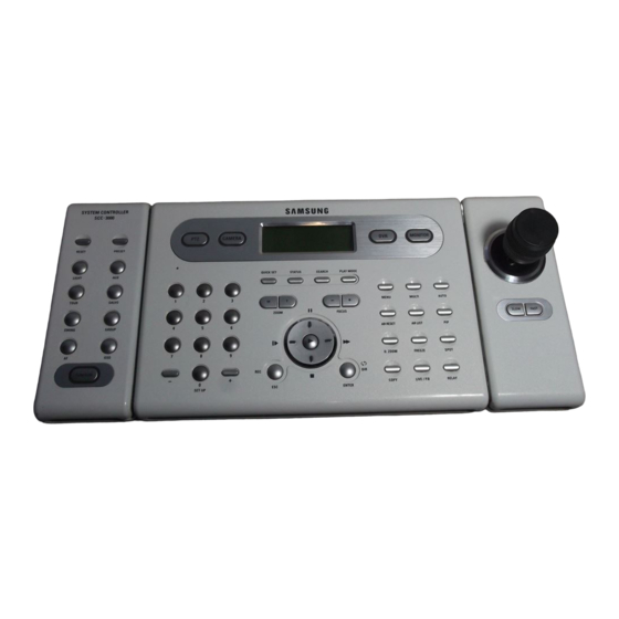
- Page 1 Thank you for buying a Samsung SYSTEM CONTROLLER. This manual will guide you through using the SYSTEM CONTROLLER. Please read this manual carefully before using the SYSTEM CONTROLLER.
-
Page 2: Table Of Contents
●System Overview ●Names and Functions of Each Part (1) Camera Setup Section (2) Number Pad (3) External Device Selectors (4) Universal Controller (5) DVR Controller (6) Camera Controller (7) Junction Box ●Before Operation (1) Power-On (2) Initial Screen Display (3) Camera ID Setup... -
Page 3: Important Safety Instructions
Important Safety Instructions ■ All work related to the installation of this appliance must be performed by qualified service personnel or system installers. - If the product is connected or installed improperly, electric shock, fire, severe injury, and/or damage can result. ■... - Page 4 Important Safety Instructions Maintenance and Repair ■ If the controller body gets dirty, turn the power off and wipe the surface with a soft cloth. - Do not use chemical agents such as alcohol or benzene. ■ For detailed information on upgrading the firmware, please direct your inquiries to the installation vendor. Refer all work related to the installation of this appliance to qualified service personnel or system installers.
-
Page 5: Major Functions And Features
Major Functions and Features (1) Overview This product is designed for use only with the Speed Dome camera, CCTV receiver, and Samsung Digital Video Recorder. ● Speed Dome camera : Samsung Techwin (SPD-1600/2200/2500), PELCO-D, PANASONIC (WV-CS854A), SAMSUNG ELECTRONICS (SCC-643-641) ● CCTV Receiver : SRX-100B ●... -
Page 6: System Overview
※ Please refer to page 39 for the detailed connection map of the JUNCTION Box, Controllers and external devices. (1) General Connection Dome Camera Junction Box 《6》 Master Controller (2) Connection Through SVR-1630 Dome Camera + DVR: 255 max. Junction Box CCD Camera Remarks : Controller Connection Cable : RS-485/422 : Video Cable Dome Camera SVR-1630: 255 max. -
Page 7: Names And Functions Of Each Part
Applies only to systems with housing and receivers that support the light function. (SRX-100B only) Applies only to systems with AUX terminals. (SRX-100B only) SPD-2200 SPD-2500 PELCO-D Not used; will be applied to F/W in the future. SAMSUNG ELECTRONICS PANASONIC (WV-CS854A) (SCC-643/641) O(AUTO-PAN) O (AUTO-SEQ) O (SCAN) 《7》... -
Page 8: Number Pad
(2) Number Pad ※ 'F' in the table below refers to the Function button. ① 0 ~ 9 : Used for entering camera ID, channel number, monitor number, DVR ID, etc. (see p.23). ② F + 0 : Activates the system setup menu (see p.24). -
Page 9: Universal Controller
① ZOOM W/T : Performs camera zoom action (wide and telephoto). ② FOCUS -/+ : Used for manual focus adjustment. ③ || : Used for moving the menu cursor up (when menu is active), pausing DVR playback, or playing stills. - Page 10 Names and Functions of Each Part ※ Some DVR controller buttons may not be supported or may be used differently than as described in this manual, depending on the DVR model. Please refer to the table below for the buttons supported by major DVR model manufacturers.
-
Page 11: Camera Controller
② SLOW : Sets the camera movement (up, down, left, and right) speed slow. ③ FAST : Sets the camera movement (up, down, left, and right) speed fast. [Joystick] (7) Junction Box [Front] Power Input Junction Box Connector Connector [Camera Control Button] [Back] DIP Switch PTZ/DVR Sub-Controller Connector Connector Reversed Connector 《11》... -
Page 12: Before Operation
▤ Always assign a unique ID to ensure that the controller IDs do not conflict with each other. ▤ SPD : SPD-1600/ SPD-2200/ SPD-2500(Samsung Techwin Co., Ltd.) (3) Camera ID Setup ① Enter a number using the number pad. -
Page 13: Joystick/Camera Control Button
Before Operation (4) Joystick/Camera Control Button ■ The joystick can be used to control the camera’ s left and right (pan) and up and down (tilt) movements. ■ The joystick can be used to control camera zoom functions. [Camera wide zoom] [Camera telephoto zoom] 《13》... -
Page 14: Camera Movement Speed Control
Before Operation (5) Camera Movement Speed Control ■ Use the joystick or press the Slow/Fast button at the bottom of the camera control button section to adjust the camera movement speed. ▤ You must press the ESC button after adjusting the camera movement speed in order to be able to use other controller buttons. -
Page 15: Ptz Mode
(1) PTZ Setup Mode ■ This menu is for setting up the PTZ camera function. It is impossible to operate Speed Dome and DVR by sub-controllers when the master controller is set to on. ① At the initial screen, press the Function button and press the 0 button to activate the [SETUP SYSTEM] menu. -
Page 16: Preset
(2-1) PRESET Setup ① At the [PTZ SETUP 1 ▶] menu, press the 1 button (see p.15). ② Use the joystick or camera control button (SCC-3000 model) to move the camera to the desired location (move up, down, left, and right, and control zoom). -
Page 17: Swing
- 2 button: Performs the vertical cycle (tilt). ▤ Move the joystick or press a controller button during the Swing operation to stop the operation. ▤ AUTO-PAN is performed automatically when the SWING button of PANASONIC(WV-CS854A) and SAMSUNG ELECTRONICS (SCC-641/643) cameras is pressed. SWING SETUP SWING SETUP... -
Page 18: Group
① At the initial screen, press the Group button. ② Press the Group button to execute the operation. ③ The Group function is performed. ▤ AUTO-SEQ and SCAN functions are performed when the GROUP button is pressed (for PANASONIC(WV-CS854A) and SAMSUNG ELECTRONICS (SCC-641/643 only). 《18》 GROUP SETUP CAM ID: GROUP SET NUM? <1-6>... -
Page 19: Tour
PTZ Mode (5) TOUR ■ This menu is for setting one or more Groups for Tour so that continuous Group operations can be carried out. The TOUR SETUP menu is only available for an SPD series. (5-1) TOUR Setup ① At the [PTZ SETUP 1▶] menu, press the 4 button (see p.15). ②... - Page 20 PTZ Mode TOUR GROUP 1 GROUP 3 《20》 GROUP 2...
-
Page 21: Model
MODEL:NONE +,-:Model Change ④ Press the + and - buttons on the number pad to change the camera type. SPD-1600/2200/2500, PELCO-D, PANASONIC(WV-CS854A) and SAMSUNG ELECTRONICS (SCC-643) types can be selected. ⑤ Press the ENTER button to finish the setup. 1:MODEL... -
Page 22: Trace
PTZ Mode (7) TRACE ■ This menu is for inputting camera movements, through joystick or camera control buttons, into the memory for a certain period of time, to allow repeating of stored movements when performing the Trace (PATTERN) function. Setting the TRACE SETUP menu by controller is only available for an SPD series. In case of products by other manufacturers, the setting has to be done by the OSD menu of the camera. -
Page 23: Ptz Setup
PTZ Mode (8) AF (Auto-Focus) ■ This menu is for adjusting camera focus manually or automatically after camera operation. If AF is set to OFF in the camera setup menu, set the AF of the controller to ON and then automatic adjustment is performed after camera operation. -
Page 24: Osd
PELCO-D - Toggle camera menu on/off (press ESC) PANASONIC (WV-CS854A) - Toggle camera menu on/off (press ESC) Samsung (SCC-643/641) - Toggle camera menu on/off (press ESC) - ESC : Cancels the menu selection. - ENTER : Selects the menu. -
Page 25: Dvr Mode
DVR ID (Menu → System Setup → Misc.). Also, for the SVR-1630 COM2 RS422/485 menu (Menu → System Setup → Serial Port), Device must be set to SCC-3000 and Interface to RS-485, and for the COM4 RS422/485 menu (Menu → System Setup → Serial Port), Device must be set to SPD2500 (if an SPD2500 is connected) and Interface to RS-485. -
Page 26: Controller Mode
INFORMATION ● Press the ESC button to move to the upper setup mode. ● The Controller Setup menu can be added to enhance controller functionality. 《26》 SETUP SYSTEM 1:PTZ 2:DVR 3:CONTROLLER Press Numeric Key CONTROLLER SETUP1 1:CONTROLLER ID 2:SERIAL 3:COPY... -
Page 27: Controller Id Setup
① At the [Controller SETUP 1 ▶] menu, press the 2 button (see p.26). ② Press the 1 button to activate the Serial 1 PORT Setup screen (PTZ camera/DVR connection PORT). Press the 2 button to activate the Serial 2 PORT Setup screen (reserved PORT). -
Page 28: Data Copy
Controller Mode (4) DATA COPY ■ This menu is for copying master controller menu data to a sub-controller. The controller ID value is not copied. ① At the [Controller SETUP 1▶] menu, press the 3 button (see p.26). ② Press a number on the number pad to enter the ID number for the sub- controller where the data will be copied. -
Page 29: Response
Controller Mode (5) RESPONSE ■ If the camera RESPONSE is set to two-way reception (RESPONSE ON), the controller RESPONSE menu must be set to ON. If the camera RESPONSE is set to one-way reception (RESPONSE OFF), the controller RESPONSE menu must be set to OFF.If this is not followed, the system may have a configuration conflict.For more information on the camera RESPONSE settings, direct your inquiries to the installation vendor. - Page 30 Controller Mode ▤ For information on camera RESPONSE settings (DIP switch settings), refer to the camera manual. (5-1) SPD-1600 DIP Setup DIP-SW 1 Not used DIP-SW 2 Reserved DIP-SW 3 RESPONSE Setup DIP-SW 4 Factory default (5-2) SPD-2200 DIP Setup DIP-SW 1 RESPONSE Setup FULL DUPLEX DIP-SW 2...
-
Page 31: Password
Controller Mode (6) PASSWORD ■ This menu is for setting the password to enter when changing controller setup values upon power-on. (6-1) PASSWORD Setup ① At the [Controller SETUP 1▶] menu, press the ▶▶ button (see p.26). ② Press the 2 button to activate the Password Setup screen. ③... -
Page 32: Applying Password-Setup Mode
Controller Mode (6-2) Applying Password – Setup Mode ① At the Password Setup screen, press the 2 button. ② Press the 1 button to ask for a password every time the setup mode is selected. Press the 2 button to skip asking for a password. (6-3) Applying Password - Power ①... -
Page 33: Priority
Controller Mode (7) PRIORITY ■ This menu is for setting the connected sub-controller to use a PTZ camera or DVR within the specified restrictions. This menu is available for master controller (ID: 1) only. ① At the [Controller SETUP 1 ▶] menu, press the ▶▶ button twice (see p.26). -
Page 34: Default
Controller Mode (8) DEFAULT ■ This menu is for resetting the changed controller setup values to the default values. ① At the [Controller SETUP 1 ▶] menu, press the ▶▶ button twice (see p.26). ② Press the 2 button to open the Default Setup screen. ③... -
Page 35: Reference
REFERENCE (1) Swing, Group Movement Speed ▤ For Swing setup, the speed setup value can be 240˚/second for pan, and 180˚/second for tilt. Setup value Degrees / second Setup value Degrees / second Setup value Degrees / second 921.19 Setup value Degrees / second Tm0.1(41 )-1155... -
Page 36: System Connections
REFERENCE (2) System Connections (2-1) Connecting Controller and Junction Box (2-2) Connecting Junction Box and External Devices JUNCTION BOX RX+ RX- TX+ TX- RX+ RX- TX+ TX- [SVR-430/900/1620 connection] * RX+ and TX+ / RX- and TX- must be short-circuited. ▤... -
Page 37: Rs-485/422 Pin Layout (D_Sub_Female)
REFERENCE (3) RS-485/422 Pin Layout (D_SUB_FEMALE) Terminal Name +12V RX+ (RS-485+) RX- (RS-485-) RX+ (RS-485 +) RX- (RS-485 -) RX+ (RS-485 +) RX- (RS-485 -) (4) RS-232C Pin Layout (D_SUB_MALE) Terminal Name PORT1 PORT1 PORT1 PORT1 PORT2 PORT2 PORT2 PORT2 PORT3 PORT3 PORT3... -
Page 38: Controller Specifications
SCC-3000 12VDC(Max 700mA) DVR & Speed Dome (SPD-2500, 1600, 2200) SPD-2500, 1600, 2200 all function control - DVR : SVR-1620 / 900 / 430 / 1630 / 1650 - PTZ : SEC, PELCO-D, PANASONIC RS-485 / RS-422 3Port Max 38400bps (Sub-controller : 56400bps) - Page 39 Samsung House, 1000 Hillswood Drive Hillswood Business Park Chertsey Surrey KT16 OPS TEL: +44 (0)1932 455 308 FAX: +44 (0)1932 455 325 TIANJIN SAMSUNG OPTO-ELECTRONICS CO., LTD . 7 Pingchang Rd, Nankai Dist, Tianjin, P.R China Post Code : 300190 TEL : +86-22-2761-4599 FAX: +86-22-2769-7558 P/No.:6806-0586-01A...