Table of Contents
Advertisement
Quick Links
REACTOR
40 MECHANICAL
™
INSTALLATION INSTRUCTIONS
Important Safety Information
WARNING
See the Important Safety and Product Information guide in the product box for product warnings and other
important information.
To avoid possible personal injury and damage to your boat, the autopilot system should be installed by a
qualified marine installer. Specific knowledge of marine steering and electrical systems is required for proper
installation.
You are responsible for the safe and prudent operation of your vessel. The autopilot is a tool that enhances your
capability to operate your boat. It does not relieve you of the responsibility of safely operating your boat. Avoid
navigational hazards and never leave the helm unattended.
Always be prepared to promptly regain manual control of your boat.
Learn to operate the autopilot on calm and hazard-free open water.
Use caution when operating the autopilot near hazards in the water, such as docks, pilings, and other boats.
CAUTION
Failure to install and maintain this equipment in accordance with these instructions could result in damage or
injury.
When in use, beware of hot surfaces on the heat-sink, motor, and solenoid components.
When in use, beware the risk of entrapment or pinching from moving parts.
Installation Preparation
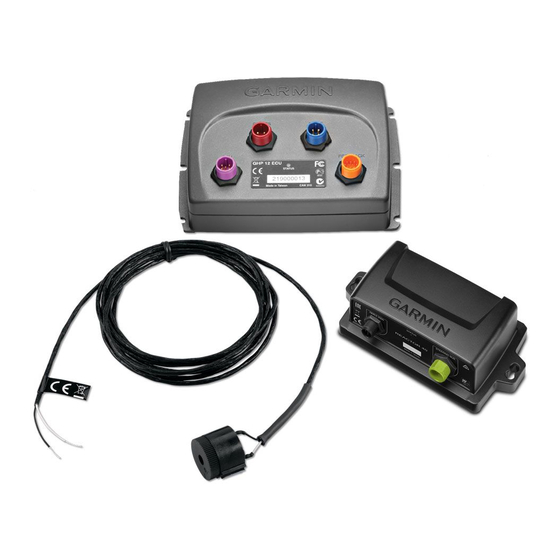
The autopilot system consists of multiple components. You should familiarize yourself with all of the
component mounting and connection considerations before beginning installation. You must know how the
components operate together in order to correctly plan the installation on your boat.
You can consult the layout diagrams to help understand the mounting and connection considerations.
You should lay out all of the components on the boat as you plan the installation to make sure your cables will
reach each component. If needed, extension cables (sold separately) for various components are available from
your Garmin
dealer or from garmin.com.
®
You should record the serial number of each component for registration and warranty purposes.
May 2022
GUID-4ECB91EB-0673-481B-84C5-473A80B7232E v3
Advertisement
Table of Contents

Related Manuals for Garmin REACTOR 40 MECHANICAL


Summary of Contents for Garmin REACTOR 40 MECHANICAL
- Page 1 You should lay out all of the components on the boat as you plan the installation to make sure your cables will reach each component. If needed, extension cables (sold separately) for various components are available from your Garmin dealer or from garmin.com. ® You should record the serial number of each component for registration and warranty purposes.
-
Page 2: Tools And Supplies Needed
Tools and Supplies Needed • Safety glasses • Drill and drill bits • Jigsaw or a rotary cutting tool (for installing an optional helm control) • Wire cutters/strippers • Phillips and flat screwdrivers • Cable ties • Solder and water-tight heat shrink tubing or water-tight, heat-shrink, butt-splice connectors •... - Page 3 If you are using the autopilot with a drive unit not sold by Garmin or a solenoid drive unit, you must install a Garmin rudder feedback sensor (recommended) or connect to an existing rudder feedback sensor using a rudder feedback cable (sold separately) (Drive Unit Installation, page 11).
-
Page 4: Component Layout
Component Layout Single-Helm Layout NOTE: This diagram is for planning purposes only. If needed, specific connection diagrams are included in the detailed installation instructions for each component. - Page 5 Mount the CCU away from sources of magnetic interference. The drive unit power cable cannot be cut or extended. If you are using the autopilot with a drive unit not sold by Garmin, you must use a drive Drive unit...
- Page 6 Finding the Best Mounting Location 1 Create a list of all suitable mounting locations for the CCU. Suitable mounting locations should not be within 60 cm (2 ft.) of the following: • Iron • Magnets • High-current wires • Intermittently-running pumps, such as head pumps and live well pumps A large magnet, such as a subwoofer-speaker magnet, should be no closer than 1.5 m (5 ft.) to any of the mounting locations.
- Page 7 (Connecting to a Solenoid Drive Unit, page 13). ◦ The solenoid power cable cannot be extended. • If you are connecting to a drive unit not sold by Garmin, you must also install a rudder feedback sensor, such as the Garmin GRF ™...
-
Page 8: Installation Procedures
A dedicated helm control is not included in all autopilot packages. If you install the autopilot without a dedicated helm control, the autopilot CCU must be connected to the same NMEA 2000 network as a compatible Garmin chartplotter to configure and control the autopilot system. - Page 9 Connecting the ECU to Power WARNING When connecting the power cable, do not remove the in-line fuse holder. To prevent the possibility of injury or product damage caused by fire or overheating, the appropriate fuse must be in place as indicated in the product specifications.
- Page 10 Item Description Splice 10 AWG (5.26 mm²) extension wire Fuse 8 in. (20.3 cm) Battery 8 in. (20.3 cm) Up to 15 ft. (4.6 m) Item Description Splice 8 AWG (8.36 mm²) extension wire Fuse 8 in. (20.3 cm) Battery 8 in. (20.3 cm) Up to 23 ft. (7 m)
-
Page 11: Drive Unit Installation
Installing a Garmin Rudder Feedback Sensor If you installed a drive unit provided by Garmin, rudder feedback data is provided by the drive unit, and a separate rudder feedback sensor is not required. If you are connecting the autopilot to a drive unit not sold by Garmin, you must also install a rudder feedback sensor, such as the GRF 10 (sold separately). - Page 12 Connecting to an Existing Drive Unit You must install a drive unit power cable to use a drive unit not sold by Garmin with the Reactor 40 Mechanical autopilot. This cable is sold separately. These instructions do not apply to a solenoid-type drive unit (Connecting to a Solenoid Drive Unit, page 13).
- Page 13 Connecting to a Solenoid Drive Unit You must install the solenoid power cable to use a solenoid drive unit with theReactor 40 Mechanical autopilot system. This cable is sold separately. These instructions apply only to solenoid-type drive units. 1 If necessary, use the installation instructions provided with the solenoid drive unit to install it on your boat. 2 If your solenoid drive unit has cables connected, disconnect the cables.
- Page 14 Installing a Garmin Rudder Feedback Sensor If you installed a drive unit provided by Garmin, rudder feedback data is provided by the drive unit, and a separate rudder feedback sensor is not required. If you are connecting the autopilot to a drive unit not sold by Garmin, you must also install a rudder feedback sensor, such as the GRF 10 (sold separately).
- Page 15 Connecting to an Existing Rudder Feedback Sensor If you connected the autopilot to a drive unit not sold by Garmin, and you plan to connect to a rudder feedback sensor not sold by Garmin, you must use a rudder feedback cable to connect your sensor to the Reactor 40 Mechanical autopilot.
- Page 16 A dedicated helm control is not included in all autopilot packages. If you install the autopilot without a dedicated helm control, the autopilot CCU must be connected to the same NMEA 2000 network as a compatible Garmin chartplotter to configure and control the autopilot system.
- Page 17 A dedicated helm control is not included in all autopilot packages. If you install the autopilot without a dedicated helm control, the autopilot CCU must be connected to the same NMEA 2000 network as a compatible Garmin chartplotter to configure and control the autopilot system.
- Page 18 A dedicated helm control is not included in all autopilot packages. If you install the autopilot without a dedicated helm control, the autopilot CCU must be connected to the same NMEA 2000 network as a compatible Garmin chartplotter to configure and control the autopilot system.
-
Page 19: Maintenance
The autopilot must be configured and tuned to your boat dynamics. You can use the Dockside Wizard and the Sea Trial Wizard on the helm control or a compatible Garmin chartplotter to configure the autopilot. See the included configuration guide for more information on configuring the autopilot. - Page 20 2.4 oz. (68 g) Temperature range From 5°F to 140°F (from -15°C to 60°C) Cable length 10 ft. (3.0 m) The device withstands incidental exposure to water of up to 1 m for up to 30 min. For more information, go to www.garmin.com/waterrating.
-
Page 21: Nmea 2000 Pgn Information
Cross track error 129284 Navigation data 130306 Wind data Helm Control A dedicated helm control is not included in all autopilot packages. To view the PGN information for a helm control device, see the product owner's manual available for download at garmin.com/manuals/ghc50. -
Page 22: Error And Warning Messages
• In Europe, call +44 (0) 870 850 1241. © 2022 Garmin Ltd. or its subsidiaries Garmin ® and the Garmin logo are trademarks of Garmin Ltd. or its subsidiaries, registered in the USA and other countries. Reactor ™ and Shadow Drive ™...