Table of Contents
Advertisement
OWNER / OPERATOR MANUAL
WARNING
The engine exhaust from this product
contains chemicals known to the State
of California to cause cancer, birth
defects or other reproductive harm.
APPLICABLE SERIAL NUMBERS :
BC3401DL
DRIVE UNIT 200101 and up
BC4401DW
DRIVE UNIT 200101 and up
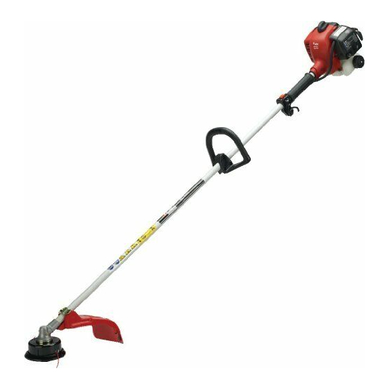
BRUSHCUTTERS
BC3401DL
BC4401DW
Thank you for purchasing a RedMax
product.
Before using our brushcutters, please
read this manual carefully to understand
the proper use of your unit.
ENGINE UNIT 200101 and up
ENGINE UNIT 200101 and up
T1196-93110(112)
Advertisement
Table of Contents

Related Manuals for RedMax BC3401DL


Summary of Contents for RedMax BC3401DL
- Page 1 DRIVE UNIT 200101 and up BC4401DW DRIVE UNIT 200101 and up BRUSHCUTTERS BC3401DL BC4401DW Thank you for purchasing a RedMax product. Before using our brushcutters, please read this manual carefully to understand the proper use of your unit. T1196-93110(112) ENGINE UNIT 200101 and up...
-
Page 2: Safety First
Read this manual carefully to understand all safety precautions, controls, proper operation and maintenance of your RedMax brushcutters. Failure to do so could result in serious injury. Instructions contained in warnings within this manual marked with a concern critical points which must be taken into consideration to prevent possible serious bodily injury, and for this reason you are requested to read all such instructions carefully and follow them without fail. -
Page 3: Table Of Contents
Safety Precautions······················································································· 4 In Order To Ensure Proper And Safe Operation Of Your Brushcutter Work Gear And Clothing Warnings Considering Handling Of Fuel Things To Check Before Using Your Brushcutter Things To Check Before Starting Up The Engine Avoid Noise Problem Things To Be Careful About When Using Your Brushcutter Notes On Care And Maintenance Of Your Brushcutter Set Up············································································································... -
Page 4: Safety Precautions
Safety Precautions In order to ensure proper and safe operation of your brushcutter • Read this Owner/Operator Manual carefully. Be sure you understand how to operate this unit properly before you use it. Failure to do so could result in serious injury. -
Page 5: Work Gear And Clothing
Warnings considering handling of fuel • The engine of the RedMax® brushcutter is designed to run on a mixed fuel which contains highly flammable gasoline. This fuel is highly flammable and you should... -
Page 6: Things To Check Before Using Your Brushcutter
15 feet (5m) or less around the brushcutter before starting the engine. • The RedMax brushcutter is equipped with a centrifugal clutch mechanism which causes the cutting blades to begin to rotate as soon as the engine is started by putting the throttle into the start position. -
Page 7: Things To Be Careful About When Using Your Brushcutter
Safety Precautions Things to be careful about when using your brushcutter • When using your brushcutter, grip the handles of the brushcutter firmly with both hands, place your feet slightly apart (slightly further apart than the width of your shoulders) so that your weight is distributed evenly across both legs, and always be sure to maintain a steady, even posture while working. -
Page 8: Notes On Care And Maintenance Of Your Brushcutter
• When replacing blade or any other parts or when replacing the oil or any lubricants, always be sure to use only RedMax products or products which have been certified by RedMax for use with the RedMax brushcutter. -
Page 9: Set Up
Set Up MOUNTING ENGINE • Put the engine onto the clutch side end of the driveshaft assembly, making the fuel tank and the cutter head come to the same side. Attach the engine firmly with the 4 screw provided. INSTALLING HANDLE •... -
Page 10: Putting On Waist Pad
Set Up PUTTING ON WAIST PAD (BC4401DW only) • Warp the waist pad around the shaft tube and the throttle wire. INSTALLING CUTTING HEAD 1. While locking the gear shaft by inserting the attached bar into the upper holder and the gear box, loosen and remove the hexagon bolt(left-handed) 2. -
Page 11: Fuel
3m(10ft) away from the fueling point before starting the engine. • The RedMax engines are lubricated by oil specially formulated for air-cooled 2-cycle gasoline engine use. If RedMax oil is not available, use an anti-oxidant added quality oil expressly labeled for air-cooled 2-cycle engine use. -
Page 12: Operation
Operation WARNING • Keep bystanders and animals at least 50 feet (15m) away from the operating point. immediately stop the engine. STARTING ENGINE 1. Rest the unit on a flat, firm place. Keep the cutting head off the ground and clear of surrounding objects as it will start rotating upon starting of the engine. -
Page 13: Stopping Engine
Operation NOTE • Avoid pulling the rope to its end or returning it by releasing the knob. Such actions can cause starter failures. 6.When the engine has started, move the choke lever gradually downward to open the choke. 7.Allow the engine to warm up for a half minute before starting operation. - Page 14 Operation growth. The rate of cutting motion will depend on the material being cut. Heavy growth will require slower action than will light growth. 5. Never swing the unit so hard as you are in danger of losing your balance or control of the unit.
-
Page 15: Optional Blade Usage
(OPT1) • When replacing blade always be sure to use products which have been certified by RedMax. WARNING • When sharpening, removing, or reattaching the blade, be sure to wear thick, sturdy gloves and use only proper tools and equipment to prevent injury. -
Page 16: Starting Engine
Optional Blade Usage OPT3 OPT4 FOR BC3401DL OPT5 OPT6 IMPORTANT Change to the debris guard which is suitable for the metal blade. (OPT3) (1) Bolt : 3540-24130 x 2 pieces (2) Spring washer : 0290-20615 x 2 pieces (3) Clamp... -
Page 17: Operation
• If you find any error to the blade, discard it and change new one which is certified by RedMax. By using the shoulder strap, hang the unit on your right side. Adjust the strap length so that the cutting head may become parallel to the ground. -
Page 18: Controlling Blade Bounce
Optional Blade Usage WARNING CONTROLLING BLADE BOUNCE • Kick out can cause serious personal injury. Carefully study this section. It is important that you understand what causes kick out, how you can reduce the chance of kick out and how you can remain in control of the unit if kick out does occur. -
Page 19: Maintenance
Optional Blade Usage OPT9 3. How you can maintain the best control: a. Keep a good, firm grip on the unit with both hands. A firm grip can help neutralize bounce. Keep your right and left hands completely around the respective handles. b. -
Page 20: Maintenance
• Never alter the brushcutter or take the engine apart. • When replacing parts, always be sure to use only RedMax products or products which have been certified by RedMax for use with the RedMax brushcutter. • Things check brushcutter REFILLING TRIMMING LINE 1. -
Page 21: Fuel Filter
For a replacement plug, use the correct type specified by RedMax(See SPECIFI- CATIONS on the page 24). • REPLACEMENT PLUG IS A CHAMPION RCJ6Y OR THE EQUIVALENT, SUCH AS BOSCH WSR8E OR NGK BPMR7A. -
Page 22: Intake Air Cooling Vent
Maintenance INTAKE AIR COOLING VENT WARNING • Never touch the cylinder, muffler, or spark plugs with your bare hands immediately after stopping the engine. The engine can become very hot when in operation, and doing so could result in severe burns. •... -
Page 23: Storage
Storage • Aged fuel is one of major causes of engine starting failure. Before storing the unit, empty the fuel tank and run the engine until it uses all the fuel left in the fuel line and the carburetor. Store the unit indoor taking necessary measures for rust prevention. -
Page 24: Specifications
Specifications BC3401DL Overall size(LxWxH) ····················································· 67.7x12.6x13.6(in) / 1720x320x345(mm) Dry weight w/o acc. ··························································································· 13.4(lbs) / 6.7(kg) Engine Type······················································································ Air-cooled 2-stroke gasoline Model ·········································································································· Zenoah G34L Displacement ······································································································· 33.6(cc) Max. output ························································································· 1.6(HP)at 7000rpm Fuel ························································································· Mixture(Gasoline 32:Oil 1) Carburetor ··················································································· Walbro Diaphragm type Spark plug ····························································································... -
Page 25: Parts List
(7) years after the machine is discontinued. It is also possible that some parts may be available even after the limit of seven (7) years.] APPLICABLE SERIAL NUMBERS : BC3401DL DRIVE UNIT 200101 and up BC4401DW DRIVE UNIT 200101 and up... - Page 26 Parts List Fig.1 DRIVE UNIT BC3401DL (S/N 200101 and up)
- Page 27 Fig.1 DRIVE UNIT BC3401DL Key# Description HOUSING JOINT ABSORBER-F ABSORBER-R BOLT BOLT BOLT DRUM, clutch BEARING SNAPRING SNAPRING BOLT PIPE COMP 1440x26xT2 GRIP DRIVE SHAFT 1480x8 Spline ø8x9 teeth HANGER ASSY • HANGER • CLAMP • SPACER • SCREW LEVER COMP •...
- Page 28 Parts List Fig.2 ENGINE UNIT BC3401DL (S/N 200101 and up)
- Page 29 Fig.2 ENGINE UNIT BC3401DL Key# Description CYLINDER BOLT GASKET, base CRANKCASE COMP. • PIN GUARD SCREW GASKET, case BEARING OIL SEAL OIL SEAL BOLT SNAP RING PISTON RING RING BEARING WASHER CRANKSHAFT COMP. SHOE, clutch SPRING SCREW WASHER WASHER ROTOR COIL ASS'Y •...
- Page 30 Parts List Fig.3 DRIVE UNIT BC4401DW (S/N 200101 and up)
- Page 31 Fig.3 DRIVE UNIT BC4401DW Key# Description HOUSING JOINT ABSORBER-F ABSORBER-R BOLT BOLT BOLT DRUM, clutch BEARING SNAPRING SNAPRING BOLT PIPE COMP 1440x26xT2.5 DRIVE SHAFT 1479x8 Spline ø8x9 teeth HANGER ASSY • HANGER • CLAMP • SPACER • SCREW BRACKET ASSY •...
- Page 32 Parts List Fig.4 ENGINE UNIT BC4401DW (S/N 200101 and up)
- Page 33 Fig.4 ENGINE UNIT BC4401DW Key# Description CYLINDER BOLT GASKET, base CRANKCASE COMP. • PIN GUARD SCREW GASKET, case BEARING OIL SEAL OIL SEAL BOLT SNAP RING PISTON RING RING BEARING WASHER CRANKSHAFT COMP. SHOE, clutch SPRING SCREW WASHER WASHER ROTOR COIL ASS'Y •...
-
Page 34: California Emission Control Warranty Statement
CALIFORNIA EMISSION CONTROL WARRANTY STATEMENT YOUR WARRANTY RIGHTS AND OBLIGATIONS THE CALIFORNIA AIR RESOURCES BOARD AND KOMATSU ZENOAH Co. ARE PLEASED TO EXPLAIN THE EMISSION CONTROL SYSTEM WARRANTY ON YOUR 1995 AND LATER LAWN AND GARDEN EQUIPMENT ENGINE. IN CALIFORNIA, NEW UTILITY AND LAWN AND GARDEN EQUIPMENT ENGINES MUST BE DESIGNED, BUILT AND EQUIPPED TO MEET THE STATE'S STRINGENT ANTI-SMOG STANDARDS. - Page 35 ZENOAH AMERICA INC. AT (770)-381-5147. IMPORTANT: YOU WILL RECEIVE A WARRANTY REGISTRATION CARD AT TIME OF PURCHASE.PLEASE FILL OUT THE CARD AND SEND IT TO RedMax / KOMATSU ZENOA AMERICA WITHIN SEVEN (7) DAYS.BE SURE TO KEEP A COPY FOR YOUR RECORDS.
- Page 36 à compter de la date de livraison initiale d’une unité. Telles sont les limites de la garantie. Le coût du transport de l'unité jusqu'au revendeur RedMax et depuis celui-ci sera à la charge de l'acheteur. L'acheteur ne supportera pas le coût de main d'oeuvre du diagnostic qui amène à la conclusion qu'une pièce garantie est défectueuse, si ce diagnostic est effectué...
-
Page 37: Emission Control Label
EMISSION CONTROL LABEL BC3401DL G34L IMPORTANT ENGINE INFORMATION THIS ENGINE CONFORMS TO US EPA PH1 FOR SMALL OFF-ROAD ENGINES. ENGINE FAMILY : 1KZXS.0344UV;EM ENGINE DISPLACEMENT : 33.6cc REFER TO OWNER'S MANUMAL FOR MAINTE- NANCE SPECIFICATIONS AND ADJUSTMENTS. MANUFACTURED KOMATSU ZENOAH CO. - Page 38 KOMATSU ZENOAH AMERICA INC. 4344 Shackleford Road Suite 500 Norcross, Georgia 30093 © Printed in Japan...