Advertisement
Quick Links
Service Manual
TOP NEXT
AD9908187C2
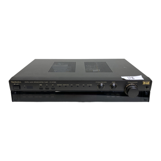
DAB Tuner
- ST-GT1000
Colour
(K)..........Black Type
Areas
(EB).......Great Britain.
(EG).......Europe.
1999 Matsushita Electric Industrial Co., Ltd. All rights reserved. Unauthorized copying and
distribution is a violation of law.
1
Advertisement

Related Manuals for Technics ST-GT1000


Summary of Contents for Technics ST-GT1000
- Page 1 Service Manual TOP NEXT AD9908187C2 DAB Tuner - ST-GT1000 Colour (K)..Black Type Areas (EB)..Great Britain. (EG)..Europe. 1999 Matsushita Electric Industrial Co., Ltd. All rights reserved. Unauthorized copying and distribution is a violation of law.
- Page 2 TOP NEXT...
- Page 3 1 Before Repair TOP PREVIOUS NEXT 1. Turn off the power supply. Using a 10 , 10 W resistor, connect both ends of power supply capacitors (C822, C833) in order to discharge the voltage. 2. Before turning the power supply on, after completion of repair, slowly apply the primary voltage by using a power supply voltage controller to make sure that the consumed current at 50 Hz in NO SIGNAL mode should be shown below with respectto supply voltage 230/240 V.
- Page 4 2 Protection Circuitry TOP PREVIOUS NEXT The protection circuitry may have operated if either of the following conditions is noticed: - No sound is heard when the power is switched ON. - Sound stops during a performance. The functions of this circuitry is to prevent circuitry damage if, for example, the positive and negative speaker connection wires are shorted, or if speaker systems with an impedance less than the indicated rated impedance of this unit are used.
- Page 5 3 Accessories TOP PREVIOUS NEXT - AC mains lead (EB) area : (RJA0053-2X)......1 pc. (EG) area : (RJA0019-2K)....1 pc. - AM loop antenna (RSA0022-J)..........1 pc. - FM indoor antenna (RSA0007)..........1 pc. - DAB T antenna (RSA0028)..........1 pc. - Stereo phono cable (RJL4P004B08)........1 pc.
- Page 6 - FM antenna plug adaptor for (EB) area only (SJP9009)..........1 pc. - Remote control transmitter (RAK-STA23WH)........1 pc. - Batteries (R6/LR6, AA, UM-3).........2 pcs. Note: These are available on sales route. TOP PREVIOUS NEXT...
- Page 7 4 Caution for AC Mains Lead TOP PREVIOUS NEXT TOP PREVIOUS NEXT...
- Page 8 7 7 7 7 7 Front Panel Controls PTY SELECT (PUSH-SEARCH) PRESET SERVICE- FREQUENCY AM ANNOUNCEMENT SECONDARY SERVICE DATA STEREO AUTO TUNING PUSH OPEN MENU ANNOUNCEMENT MEMORY MEMORY PRIMARY/ TUNING ENTER DISPLAY CANCEL DELETE AUTO MEMORY SECONDARY DATA ATUO/MANUAL 10 11 13 14 15 16 TUNING MODE SERVICE...
- Page 9 7 7 7 7 7 Equipment Connections Amplifier (not included) TUNER Stereo phono cable (included) This unit AM ANT FM ANT DAB ANT EXT LOOP OPTICAL OUT LINE OUT AC IN AUDIO RDI Optical cables AC mains lead (not included) To household (included) DIGITAL...
- Page 10 7 7 7 7 7 Antenna Connections The included antennas are sufficient under normal conditions. FM indoor antenna (included) Installing outdoor antennas Fix the other end of the antenna where reception is best. FM outdoor antenna (not included) Adhesive tape Note Disconnect the FM indoor antenna.
- Page 11 To connect a 300 Ω feeder wire DAB outdoor antenna (not included) Loosen the screws, connect the wires, and tighten the screws to secure the connection. The illustration shows an example of installation. The antenna plug adaptor (included) does not have to be used if the plug on the antenna cable is suitable.
- Page 12 7 7 7 7 7 DAB and RDS What is DAB? DAB stands for digital audio broadcasting. It is a new form of radio Other features and DAB functions available with this unit that is broadcast digitally. Unlike regular analog broadcasting, digital radio deteriorates less, and is thus able to provide quality sound DAB use digital broadcasting to provide other useful features.
- Page 13 7 7 7 7 7 Tuning Use to tune to DAB services and FM and AM radio stations. STEREO Preparation: Press [PUSH OPEN] to open the front panel. Press [ /I]. The unit comes on. Press [DAB], [FM], or [AM] to select the band. SECONDARY SERVICE PRIMARY/ SECONDARY...
- Page 14 7 7 7 7 7 The Display Actual displays depend on the broadcast. You can change the display during reception of DAB and FM RDS broadcasts to view the different types of information. Preset channel numbers are displayed whenever preset tuning is used.
- Page 15 7 7 7 7 7 DAB Functions Using the announcement function Program the unit to switch automatically to announcements when they start. You are able to choose the variety and language of the announcements. The previous broadcast resumes when the announcement is finished.
- Page 16 Using announcement services While listening to DAB ANNOUNCEMENT Press and hold [-ANNOUNCEMENT –CANCEL] for about two seconds. The “ANNOUNCEMENT” indicator lights and the unit is ready to receive announcement services. When an announcement service you turned on in the settings steps is received, the unit automatically plays that announcement ( a The “ANNOUNCEMENT”...
- Page 17 Checking DAB reception quality The function allows you to check reception quality to improve the position of the antenna. While listening to DAB. Press [MENU]. Press [+] three times to display “SIGN. QUAL- ITY”. Change the position of the antenna so the meter lengthens. Press [MENU].
- Page 18 7 7 7 7 7 Preset Tuning Put DAB services and FM and AM stations into this unit’s preset channels to make tuning simple. There are two methods of preset tuning; auto, where the unit pre- sets all the services and stations it can receive automatically, and; manual, where you can select the services and stations to preset.
- Page 19 Manual presetting 1 2 1 4 This allows you to preset the services and stations you want in the channels you want. Tune to the broadcast. You cannot preset in DAB if nothing is being received. (“NO SIGNAL” or “NO SERVICE” is displayed.) Press [-MEMORY –AUTO MEMORY].
- Page 20 7 7 7 7 7 PTY Search with DAB and RDS You can use the PTY signals included in DAB and RDS broadcasts to find particular types of programs. 1 2 1 3 Note PTY search is performed on preset channels. Do the preset- ting procedures before continuing.
- Page 21 6 Operation Checks and Component Replacement/ Procedures TOP PREVIOUS NEXT...
- Page 22 TOP PREVIOUS NEXT...
- Page 23 7.1 Schematic Diagram Notes TOP PREVIOUS NEXT This schematic diagram may be modified at any time with the development of new technology. Notes: S401: Setting switch (MENU -) S402: Setting switch (MENU+) S403: Memory delete switch (-MEMORY DELETE) S404: Display mode select switch (DISPLAY) S405: Memory switch (-MEMORY—AUTO MEMORY) S406:...
- Page 24 - < > : DAB - Important safety notice: Components identified by ; mark have special characteristics important for safety. Furthermore, special parts which have purposes of fire-retardant (resistors), high-quality sound (capacitors), low-noise (resistors), etc. are used. When replacing any of components, be sure to use only manufacturers specified parts shown in the parts list.
- Page 25 SCHEMATIC DIAGRAM 1 Note: The number which noted at the connectors on the schematic diagram as "SCHEMATIC DIAGRAM 1" or "SCHEMATIC DIAGRAM 2" indicates the schematic diagram serial number located on the left corner in the schematic diagram. :FM SIGNAL LINE :AM SIGNAL LINE TUNER CIRCUIT :POSITIVE VOLTAGE LINE...
- Page 26 SCHEMATIC DIAGRAM 2 :POSITIVE VOLTAGE LINE :FM SIGNAL LINE :AM SIGNAL LINE :AM OSC SIGNAL LINE R104 R109 R106 R108 CF202 470K 470K C105 (0V) 1000P (0V) 3.8V CF201 C104 (0V) (0V) 3.8V 1000P 0.7V 0.7V Q106 UN4111TA Q101 Q102 POWER SUPPLY LINE (FM:ON)
- Page 27 SCHEMATIC DIAGRAM 3 MAIN CIRCUIT :POSITIVE VOLTAGE LINE R534 R524 B C D C529 C530 R520 R518 R521 R519 R522 R515 R525 (3.3V) 75 74 73 72 71 70 69 68 67 66 65 0.1V R513 3.3V 2.3V 3.3V 3.3V 3.3V 3.3V 3.3V...
- Page 28 SCHEMATIC DIAGRAM 4 :POSITIVE VOLTAGE LINE :NEGATIVE VOLTAGE LINE :DAB SIGNAL LINE R601 R112A R115A 4.7K R113A C112A 2.7K R111A 4.7K 13.2V 14.8V 1.6V IC601 IC111 TC74HCT7007A NJM318MTE1 INTERFACE OPE AMP C116A 6.3V100 1.6V 1.6V 14.4V C114A R531 IC502 W24258S70LET 256K SRAM R533 3.3V...
- Page 29 SCHEMATIC DIAGRAM 5 MAIN CIRCUIT :POSITIVE VOLTAGE LINE :NEGATIVE VOLTAGE LINE :DAB SIGNAL LINE A B D C205 R201 330P R606 IC602 R607 TC74HCT7007A R608 3.3V TO 5V CONVERTER R614 (3.3V) (5V) (3.3V) (5V) 3.3V 3.3V 3.3V IC603 TC74HC4050EL 5V TO 3.3V CONVERTER 0.1V 0.1V...
- Page 30 SCHEMATIC DIAGRAM 6 :POSITIVE VOLTAGE LINE :NEGATIVE VOLTAGE LINE :DAB SIGNAL LINE TP313 TP314 TP315 TP312 R309 TP316 TP311 R307 TP310 R306 R310 0.3V (0V) RAD6 SDAT 1.4V (0V) (0V) 1.6V RAD3 3.3V SCLK 0.3V (0V) 2.8V RAD2 SLRCK 0.3V (0V) (0V) 1.6V...
- Page 31 SCHEMATIC DIAGRAM 7 :FM SIGNAL LINE :POSITIVE VOLTAGE LINE :AM SIGNAL LINE CONNECTOR CIRCUIT MAIN CIRCUIT :NEGATIVE VOLTAGE LINE :DAB SIGNAL LINE R216 CN203 R932 CN201A CN201B R215 Rch IN TUNER R214 CIRCUIT R213 Lch IN (CN102B) R212 R931 on SCHEMATIC R211 DIAGRAM 2 R210...
- Page 32 SCHEMATIC DIAGRAM 8 OPERATION CIRCUIT :POSITIVE VOLTAGE LINE :NEGATIVE VOLTAGE LINE FL401(RSL0286 F) FL DISPLAY 6 7 8 9 10 11 12 13 14 15 16 17 18 19 20 21 22 23 24 25 26 27 28 29 30 31 32 33 34 35 36 37 38 39 40 41 42 43 44 45 46 47 48 49 50 51 52 53 54 55 56 57 58 59 60 61 62 63 64 65...
- Page 33 SCHEMATIC DIAGRAM 9 :POSITIVE VOLTAGE LINE :NEGATIVE VOLTAGE LINE W401 POWER SUPPLY CIRCUIT 36.3V (CN401) on D.GND SCHEMATIC DIAGRAM 10 +B(5) 3.3V +B(6) STBYLED VR413 (SERVICE/ FREQUENCY) W402 S403 JOGPTYA MAIN CIRCUIT MEMORY DELETE) D.GND (CN402) on KEY2 SCHEMATIC DIAGRAM 3 S405 W403 MEMORY...
- Page 34 SCHEMATIC DIAGRAM 10 POWER SUPPLY CIRCUIT :POSITIVE VOLTAGE LINE :NEGATIVE VOLTAGE LINE Q817 2SB621AQSTA ICP818 D813 REGULATOR C812 SRUN10T RL1N4003N02 50V100 36.3V 36.9V R820 R811 Q821 UN4214TA LED DRIVE 31.9V CN401 3.7V STBYLED +B(6) 32.5V 32.5V OPERATION +B(5) Q811,812 Q811 CIRCUIT(W401) D.GND 2SD1450RSTA...
- Page 35 SCHEMATIC DIAGRAM 11 :POSITIVE VOLTAGE LINE RL811 IC811 BA09ST V5 REGULATOR D811 13.9V 13.9V MA165TA 8.1V 4.7K 8.1V Q816 DTC143ZSATP RELAY DRIVE D821 824 RL1N4003N02 R802 D821 1/6W0.15 D822 D823 D824 IC831 BA09ST V5 REGULATOR D834 837 RL1N4003N02 13.9V (0V) (0V) R803 D834...
- Page 36 MAIN P.C.B. (SIDE : A) TP511 TP501 TP512 CN403 CN402 CN407 CN406 3 4 5 6 7 1 2 3 1 2 3 4 5 6 1 2 3 CN802 E501 TP801 C517 IC502 CN801 TP805 TP804 TP802 C528 R525 TP803 TP807 C501...
- Page 37 MAIN P.C.B. (SIDE : B) (CN406) (CN407) (CN402) (CN403) 4 3 2 1 5 4 3 2 1 3 2 1 7 6 5 4 3 2 1 (CN802) (TP512) (C517) (TP501) (CN801) (TP511) (TP514) (TP515) (C514) (C202) (X501) (C201) (TP513) (Z101A) (C336)
- Page 38 ELECTRICAL PARTS LOCATION Ref. No. Lo. No. Ref. No. Lo. No. Ref. No. Lo. No. Ref. No. Lo. No. Ref. No. Lo. No. MAIN P.C.B. ( SIDE : A ) IC111 E501 R515 R922 C327 IC201 R101 R516 R923 C328 IC301 R111A R517...
- Page 39 TUNER P.C.B. AM ANT FM ANT (LOOP) (75 ) (EXT) ELECTRICAL PARTS LOCATION Ref. No. Lo. No. Ref. No. Lo. No. L102 L101 TUNER P.C.B. JK101 IC101 R136 IC102 R137 Q101 R138 Z101 CN101B Q102 R139 Z120 Q106 R140 Q110 R141 FRONT END) D101...
- Page 40 OPERATION P.C.B. (SIDE : A) W404A W403 W402 W407 1 2 3 4 5 6 7 1 2 3 1 2 3 4 5 6 VR413 D407 D409 (SERVICE/ (AUTO TUNING) (RDS R408 FREQUENCY) R406 1 2 3 R413 R427 C421 C417 R424...
- Page 41 W401 W407 W406 1 2 3 4 1 2 3 4 5 6 D404 D403 D402 D401 D410 D407 D406 D405 (SECONDARY D409 (AM) (FM) (DAB) (STEREO) (DATA) SERVICE) (ANNOUNCEMENT) (AUTO TUNING) (RDS) R408 R406 R407 R405 R413 R412 R411 R410 R429 R409...
- Page 42 CONNECTOR P.C.B. CN203 CN204 7 6 5 4 3 2 1 7 6 5 4 3 2 1 C213 C210 C212 CN201B CN202B 7 6 5 4 3 2 1 7 6 5 4 3 2 1 (REP2872A-S) SENSOR P.C.B. S414 (MENU) ELECTRICAL PARTS LOCATION...
- Page 43 POWER SUPPLY P.C.B. ELECTRICAL PARTS CN804 CN401 LOCATION 4 3 2 1 4 3 2 1 Q831 Ref. Ref. R834 POWER SUPPLY P.C.B. Q821 IC831 Q834 W802 Q835 IC811 R803 IC821 R811 IC822 R812 IC831 D839 R813 R822 IC832 R814 C834 ICP836 C828...
- Page 44 POWER SW P.C.B. W804 1 . . 4 FM ANT TUNER P.C.B. AM ANT 1 ..7 1 . . 4 CN101B CN102B CN401 1 ..7 1 ..7 CN804 W802 W801...
- Page 45 AM ANT FM ANT Z120 (FM FRONT END) Z101 CF201 RF amp. FM mixer coil coil Q101, Buffer FM IF Local OSC amp. amp. LA1833MN-TLM IC101 FM / AM I F AMP , DET / AM OSC, CF202 MIX / FM MPX +B(FM) Q110 Switch-...
- Page 46 D401~410 (DAB/FM/AM/SECONDARY SERVICE/DATA/STEREO/ RDS/AUTO TUNING/ ANNOUNCEMENT) 7~15 TP512 Q3~11 BU2090AFE2 VR413 VR414 VR415 (FREQUENCY/ IC402 (PTY SELECT) (PRESET) SERVICE) LED DRIVE S80725SNDNT1 TP513 DATA IC504 X501 TP511 (19.66MHz) Reset 7,29,50, 19~22 68,98,119 MN1021617BA IC501 SYSTEM CONTROL 8,69 TC74HCT7007A TC74HC4050EL IC602 Z401 IC603 3.3V To 5V...
- Page 47 DAB ANT TP110 IF OUT TP304 TP101 NULL DAB RF NULL TUNER TC74HCT7007A IC601 INTERFACE TP501 Z101 81 80 NDACRST NRST MN1021617BA DABOFF IC501 SYSTEM CONTROL PWROFF 103~111, 3~6, 114~118, 9~12 1~10, 11~13, TP514 TP515 23~26 15~19 A0~14 I/O1~8 CE OE WE AK93C85AM-E1 W24258S70LET IC503...
- Page 48 MN66710 M514400D6SJ1 IC301 IC302 12,48, 4M DRAM 61,74 NJM318MTE1 41~47,50, 5~9, VREF Vss0,2.3 AVss IC111 51,54 11~15 RAD0~9 A0~9 1,2, ADIN RDT0~3 57~60 18,19 amp. DQ0~3 ADVRT OFDM NRAMOE gen. ADVRB De-interleave NRRAS IQMOD NRCAS NULL NULDET NRAMWE FSYO TP301 13,31, X301 49,75...
- Page 49 NJM2115MTE1 IC902 +B8 +B8 AK4321VF-E1 Buffer IC901 amp. AD/DA CONVERTER SDATA SCLK BICK VCOM SLRCK LRCK Serial input De-emphasis interface control NJM4580EDTE1 LINE OUT (Lch) IC903(904) NDACRST AOUTL Buffer interpolator Q905,907 amp. Modulator (Q906,908) AOUTR Muting R ch interpolator RL901 Modulator Q903 Clock OSC/Divider...
- Page 50 S80725SNDNT1 MN1021617BA 128PIN 28PIN W24258S70LET MN66710 84PIN 24PIN LC72722PMTLM 24PIN AK4321VF-E1 16PIN BU2090AFE2 No.1 24PIN LA1833MN-TLM 20PIN LC72131MDTLM No.1 NJM2115MTE1 XC62FP3302MR M514400D6SJ1 TC74HCT7007A 14PIN NJM4580EDTE1 16PIN TC74HC4050EL NJM318MTE1 AK93C85AM-E1 No.1 BA05ST-V5 MSM920101GSK UPC29L04J-T 2SB621AQSTA 2SC2787LTA BA09ST-V5 UN4111TA BA033ST-V5 2SC3311ARSTA ..
- Page 51 SCREW RMZ0339 ZNR COVER XYN3+F8 SCREW RHN94002 RHW10008 WASHER RKA0053-A FOOT RMG0270-K RUBBER RDG0449 DAMPER GEAR RGB0031-A TECHNICS BADGE RGB0111-N DAB BADGE RGG0169-K PANEL RGK1111-K RGK1168-K RING ORNAMENT 1 RGK1169-K RING ORNAMENT 2 RGK1170-K1 FL PANEL RGK1171-K DISPLAY 1 RGK1172-K...
- Page 52 Ref. No. Part No. Part Name& Description Pcs. Remarks RGP0742-K SUB GRILL RGP0743A-K GRILL RGU0890-1K BUTTON,POWER RGU1712-K BUTTON,OPEN RGU1775-K BUTTON,DATA RGU1776-K BUTTON,MENU RGU1777-K BUTTON,SELECT RGW0322-K KNOB RGW0323-K KNOB RGW0324-K KNOB RHD26033 SCREW RHD26034 SCREW RHN70002 RKF0595-Q DOOR RKG0009 MAGNET RKW0273A-K FILTER RME0284 SPRING...
- Page 53 Ref. No. Part No. Part Name& Description Pcs. Remarks C105A ECEA0JKS101 6.3V 100U C106 ECBT1C103NS5 16V 0.01U C106A ECEA0JKS101 6.3V 100U C107 ECBT1H473ZF5 50V 0.047U C108 ECBT1H8R2KC5 50V 8.2P C109 ECBT1H102KB5 50V 1000P C110 ECBT1C103NS5 16V 0.01U C111 ECEA1EKS4R7 25V 4.7U C112 ECBT1C103NS5 16V 0.01U...
- Page 54 Ref. No. Part No. Part Name& Description Pcs. Remarks C302,03 ECUV1H150JCV 50V 15P C304 ECEA0JKS101 6.3V 100U C305-11 ECUVNC104ZFV 16V 0.1U C312 ECEA0JKS101 6.3V 100U C313 ECUVNC104ZFV 16V 0.1U C314 ECUV1H010CCV 50V 1P C321 ECEA0JKS101 6.3V 100U C322 ECUVNC104ZFV 16V 0.1U C323 ECEA0JKS101 6.3V 100U...
- Page 55 Ref. No. Part No. Part Name& Description Pcs. Remarks C835 ECEA1CKS101 16V 100U C837 ECBT1C103NS5 16V 0.01U C838 ECEA0JKS101 6.3V 100U C839 ECBT1C103NS5 16V 0.01U C840 RCE1CKA470BG 16V 47U C842 ECBT1H104ZF5 50V 0.1U C843 ECEA1CKS101 16V 100U C851 ECFTD103KXL 50V 0.01U C852,53 RCE1EM471BV 25V 470U...
- Page 56 Ref. No. Part No. Part Name& Description Pcs. Remarks D826,27 MA165 DIODE D831,32 MA165 DIODE D833 MA4033M DIODE D834-37 RL1N4003N02 DIODE D838 MA4091L DIODE D839 RL1N4003N02 DIODE D851,52 RL1N4003N02 DIODE D853,54 MA4160M DIODE D855 MA165 DIODE D901 RL1N4003N02 DIODE D902,03 MA142WATX DIODE XBA2C20TB0...
- Page 57 Ref. No. Part No. Part Name& Description Pcs. Remarks L101A ELJPC100KF COIL L102 ELESNR68MA COIL L102A ELJPC100KF COIL L103 ELEXTR47MA9 COIL L103A ELJPC100KF COIL L105,06 ELJPC100KF COIL L201 ELJPC100KF COIL L301,02 ELJPC100KF COIL L321 ELJPC100KF COIL L401 ELJPC100KF COIL L501,02 ELJPC100KF COIL L801...
- Page 58 Ref. No. Part No. Part Name& Description Pcs. Remarks R107 ERDS2FJ331 1/4W 330 R108 ERDS2FJ474 1/4W 470K R109 ERDS2FJ331 1/4W 330 R110 ERDS2FJ102 1/4W 1K R111 ERDS2FJ391 1/4W 390 R111A ERA3YED472 1/16W 4.7K R112 ERDS2FJ104 1/4W 100K R112A ERA3YED472 1/16W 4.7K R113 ERDS2FJ103 1/4W 10K...
- Page 59 Ref. No. Part No. Part Name& Description Pcs. Remarks R306 EXBV8V102J 1/16W 1K R307 ERJ3GEYJ102Z 1/16W 1K R308 ERJ3GEYJ103Z 1/16W 10K R309-11 EXBV8V470J 1/16W 47 R313,14 EXBV8V470J 1/16W 47 R315 ERJ3GEYJ103Z 1/16W 10K R316 ERJ3GEY0R00V 1/16W 0 R317 EXBV8V102J 1/16W 1K R318 ERJ3GEYJ103Z 1/16W 10K...
- Page 60 Ref. No. Part No. Part Name& Description Pcs. Remarks R520-22 ERJ3GEY0R00V 1/16W 0 R524 EXBV8V103J 1/16W 10K R525 EXBV4V470J 1/32W 47 R526,27 EXBV8V101J 1/16W 100 R528,29 EXBV8V470J 1/16W 47 R530 ERJ3GEYJ470V 1/16W 47 R531 EXBV8V470J 1/16W 47 R532,33 ERJ3GEYJ470V 1/16W 47 R534 ERJ3GEYJ153V 1/16W 15K...
- Page 61 Ref. No. Part No. Part Name& Description Pcs. Remarks R924 ERJ3GEYJ151V 1/16W 150 R925,26 ERJ3GEYJ473V 1/16W 47K R927 ERJ3GEYJ222V 1/16W 2.2K R931,32 ERJ3GEY0R00V 1/16W 0 R933,34 ERJ3GEYD103V 1/16W 10K R935,36 ERJ3GEYD222V 1/16W 2.2K RJ101 ERJ3GEY0R00V 1/16W 0 RL811 RSY0041M-0 RELAY RL901 RSY0044M-A RELAY...
- Page 62 13 Cabinet Parts Location TOP PREVIOUS NEXT...
- Page 63 TOP PREVIOUS NEXT...
- Page 64 14 Packaging TOP PREVIOUS TOP PREVIOUS...