Table of Contents
Advertisement
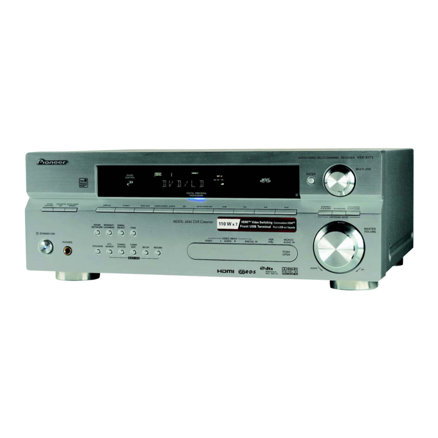
AUDIO/VIDEO MULTI-CHANNEL
RECEIVER
VSX-917V
Register your product at
www.pioneerelectronics.com (US)
www.pioneerelectronics.ca (Canada)
• Protect your new investment
The details of your purchase will be on file for reference in the event of an
insurance claim such as loss or theft.
• Receive free tips, updates and service bulletins on
your new product
• Improve product development
Your input helps us continue to design products that meet your needs.
• Receive a free Pioneer newsletter
Registered customers can opt in to receive a monthly newsletter.
Operating Instructions
Advertisement
Table of Contents

Related Manuals for Pioneer VSX-917V


Summary of Contents for Pioneer VSX-917V
-
Page 1: Operating Instructions
• Receive free tips, updates and service bulletins on your new product • Improve product development Your input helps us continue to design products that meet your needs. • Receive a free Pioneer newsletter Registered customers can opt in to receive a monthly newsletter. Operating Instructions... - Page 2 Product Name: AUDIO/VIDEO MULTI-CHANNEL RECEIVER Model Number: VSX-917V-K, VSX-917V-S Responsible Party Name: PIONEER ELECTRONICS SERVICE INC. Address: 1925 E. DOMINGUEZ ST. LONG BEACH, CA 90801-1760, USA Phone: 1-800-421-1404 If the AC plug of this unit does not match the AC outlet you want to use, the plug must be removed and appropriate one fitted.
- Page 3 The lightning flash with arrowhead, within an equilateral triangle, is intended to alert the user to the presence of uninsulated "dangerous voltage" within the product's enclosure that may be of sufficient magnitude to constitute a risk of electric shock to persons. READ INSTRUCTIONS —...
-
Page 4: Table Of Contents
Thank you for buying this Pioneer product. Please read through these operating instructions so you will know how to operate your model properly. After you have finished reading the instructions, put them away in a safe place for future reference. - Page 5 09 Controlling the rest of your system Operating other Pioneer components ..47 Setting the remote to control other components ......47 Selecting preset codes directly .
-
Page 6: Before You Start
Before you start Chapter 1: Before you start Checking what’s in the box Please check that you've received the following supplied accessories: • Setup microphone • Remote control unit • Dry cell batteries (AA size IEC R6) x2 • AM loop antenna •... -
Page 7: 02 5 Minute Guide
5 minute guide Chapter 2: 5 minute guide Introduction to home theater Home theater refers to the use of multiple audio tracks to create a surround sound effect, making you feel like you're in the middle of the action or concert. The surround sound you get from a home theater system depends not only on your speaker setup, but also on the source and the sound settings of the receiver. -
Page 8: Automatically Setting Up For Surround Sound
5 minute guide Automatically setting up for surround sound (MCACC) The Auto Multi-Channel Acoustic Calibration (MCACC) setup measures the acoustic characteristics of your listening area, taking into account ambient noise, speaker size and distance, and tests for both channel delay and channel level. - Page 9 5 minute guide Follow the instructions on-screen. • Make sure the microphone is connected. • If you’re using a subwoofer, it is automatically detected every time you switch on the system. Make sure it is on and the volume is turned up. •...
-
Page 10: Other Problems When Using The Auto Mcacc Setup
5 minute guide • Speaker Setting – The size and number of speakers you’ve connected (see page 41 for more on this) • Speaker Distance – The distance of your speakers from the listening position (see page 43 for more on this) •... -
Page 11: Connecting Up
Connecting up Chapter 3: Connecting up Making cable connections Important • Before making or changing connections, switch off the power and disconnect the power cord from the AC outlet. • Make sure not to bend the cables over the top of this unit. If this happens, the magnetic field produced by the transformers in this unit may cause a humming noise from the speakers. -
Page 12: About The Video Converter
Connecting up About the video converter When the video converter is enabled, all analog video sources are output through all of the MONITOR VIDEO OUT jacks (HDMI and high- definition progressive component video cannot be converted). See Digital Video Converter Setup on page 65 to switch the video converter on or off. -
Page 13: Connecting A Dvd Player And Tv
Connecting up Connecting a DVD player and TV This page shows you how to connect your DVD player and TV to the receiver. Connect a coaxial digital audio output on your DVD player to the DIGITAL COAX 1 (DVD/LD) input on this receiver. Use a coaxial digital audio cable for the connection. -
Page 14: Connecting The Multichannel Analog
Connecting up Connecting the multichannel analog outputs For DVD Audio and SACD playback, your DVD player may have 5.1 channel analog outputs.In this case, you can connect the multichannel analog outputs to the multichannel inputs of this receiver as shown below. This receiver DIGITAL OUT FM UNBAL... -
Page 15: Connecting Other Audio Components
Connecting up Connecting other audio components The number and kind of connections depends on the kind of component you’re connecting. Follow the steps below to connect a CD-R, MD, DAT, tape recorder or other audio component. If your component has a digital output, connect this to a digital input on the receiver as shown. -
Page 16: Connecting Other Video Components
Connecting up However, the connected DVD player, set-top box, etc. must be able to output WMA9 Pro format audio signals through a coaxial or optical digital output. ® Microsoft, Windows Media , and the Windows logo are trademarks, or registered trademarks of Microsoft Corporation in the United States and/or other countries. -
Page 17: Using The Component Video Jacks
Connecting up Using the component video jacks Component video should deliver superior picture quality when compared to composite video. A further advantage (if your source and TV are both compatible) is progressive-scan video, which delivers a very stable, flicker-free picture. See the manuals that came with your TV and source component to check whether they are compatible with progressive-scan video. -
Page 18: Connecting Antennas
Connecting up Connecting antennas Connect the AM loop antenna and the FM wire antenna as shown below. To improve reception and sound quality, connect external antennas (see Using external antennas on page 18). fig. a fig. b FM UNBAL LOOP Pull off the protective shields of both AM antenna wires. -
Page 19: Connecting The Speakers
Connecting up Connecting the speakers A complete setup of eight speakers (including the subwoofer) is shown here but everyone’s home setup will vary. Simply connect the speakers you have in the manner shown below. will work with just two stereo speakers (the front speakers in the diagram) but using at least three speakers is recommended, and a complete setup is best. -
Page 20: Hints On Speaker Placement
Connecting up Make sure that the speaker cable you’re using is properly prepared with about 10 mm ( of insulator stripped from each wire, with the exposed wire strands twisted together (fig. A). Unscrew the terminal a few turns until there is enough space to insert the exposed wire (fig. -
Page 21: Ac Outlet
Connecting up Overhead view of speaker setup You can also refer to the 3-D speaker setup illustration on page 7. Front Center left Subwoofer Surround left Listening position Surround back left Surround back Single surround back speaker The diagrams below show suggested surround and surround back speaker orientation. -
Page 22: Controls And Displays
10 STANDBY/ON Switches the receiver between on and standby. 11 VIDEO INPUT See Connecting to the front panel video terminal on page 17. VSX-917V MULTI JOG ENTER STEREO/ ADVANCED SIRIUS F.S.SURR... -
Page 23: Display
Controls and displays 12 MCACC/AUDIO IN jack Use to connect a microphone when performing Auto MCACC setup, or connect an auxiliary component using a stereo mini-jack cable (page 17). 13 MASTER VOLUME dial 14 SOUND RETRIEVER Press to restore CD quality sound to compressed audio sources (page 33). - Page 24 Controls and displays DIGITAL – Lights when a digital audio signal is detected. 2 DIGITAL – Lights when a Dolby Digital encoded signal is detected. ANALOG – Lights when an analog signal is detected. DTS – Lights when a source with DTS encoded audio signals is detected.
-
Page 25: Remote Control
Controls and displays Remote control RECEIVER INPUT SOURCE SELECT F.AUDIO TV CTRL CD-R/TAPE XM RADIO SIRIUS RECEIVER SLEEP SB ch DIMMER SIGNAL SEL D.ACCESS CLASS ENTER TOP MENU MENU TUNE DTV MENU T.EDIT ENTER SETUP RETURN TUNE CATEGORY GUIDE TV CONTROL INPUT TV CH TV VOL... - Page 26 Controls and displays MENU – Displays the disc menu of DVD- Video discs. It also displays TV and DTV menus. T.EDIT – Press to memorize and name a station for recall (page 44). SETUP (Press RECEIVER first to access) Use to access the System Setup menu (see page 35).
-
Page 27: Operating Range Of Remote Control
Controls and displays PHASE – Press to switch on/off Phase Control (page 10). ACOUSTIC EQ – Press to select an Acoustic Calibration EQ setting (page 31). DIALOG – Use to make dialog stand out when watching TV or a movie (page 33). SOUND RETRIEVER –... -
Page 28: Listening To Your System
Listening to your system Chapter 5: Listening to your system Important • Certain features explained in this section will not be possible depending on the source (for example, PCM 88.2 kHz / 96 kHz, DTS 96 kHz (24 bit) or WMA9 Pro sources). -
Page 29: Using The Advanced Surround Effects
Listening to your system • Neo:6 MUSIC – 6.1 channel sound, especially suited to music sources With multichannel sources, if you have connected surround back speaker(s) and have selected SB ON, you can select (according to format): • 2 Pro Logic IIx MOVIE – See above •... -
Page 30: Listening In Stereo
Listening to your system Setting What it does Center Adjusts the center image to create a wider stereo effect with Image vocals. Adjust the effect from 0 (Applicable (all center channel sent to front only when right and left speakers) to 10 using a cen- ter speaker) (center channel sent to the... -
Page 31: Listening With Acoustic Calibration Eq
Listening to your system • While listening to a source, press AUTO SURR to select the Stream Direct mode. • AUTOSURR. – See Auto playback on page 28. • DIRECT – Sources are heard according to the settings made in the Surround Setup (speaker setting, channel level, speaker distance), as well as with dual mono, Center Width, Dimension and Panorama... -
Page 32: Using Virtual Surround Back (Vsb)
Listening to your system Using Virtual Surround Back (VSB) When you’re not using surround back speakers, selecting this mode allows you to hear a virtual surround back channel through your surround speakers. You can choose to listen to sources with no surround back channel information, or if the material sounds better in the format (for example, 5.1) for which it was originally encoded, you can have the... -
Page 33: Using The Sound Retriever
Listening to your system Using the Sound Retriever When audio data is removed during the compression process, sound quality often suffers from an uneven sound image. The Sound Retriever feature employs new DSP technology that helps bring CD quality sound back to compressed 2-channel audio by restoring sound pressure and smoothing jagged artifacts left over after compression. -
Page 34: Selecting The Multichannel Analog Inputs
Listening to your system • DIGITAL – Selects an optical or coaxial digital signal. When set to DIGITAL or AUTO, 2 DIGITAL lights when a Dolby Digital signal is input, and DTS lights when a DTS signal is input. Selecting the multichannel analog inputs If you have connected a decoder or a DVD player with multichannel analog outputs to this... -
Page 35: The System Setup Menu
The System Setup menu Chapter 6: The System Setup menu Making receiver settings from the System Setup menu The following section shows you how to make detailed settings to specify how you’re using the receiver (for example, if you want to set up two speaker systems in separate rooms), and also explains how to fine-tune individual speaker system settings to your liking. -
Page 36: Manual Mcacc Speaker Setup
The System Setup menu Select ‘Surr Back System’ from the System Setup menu. See Making receiver settings from the System Setup menu above if you’re not already at this screen. System Setup 1.Surr Back System 2.Auto MCACC 3.Manual MCACC 4.Manual SP Setup 5.Input Assign 6.Other Setup : Exit... -
Page 37: Fine Channel Level
The System Setup menu • EQ CUSTOM1/2 Adjust – Make detailed manual adjustments to your custom Acoustic Calibration EQ settings (see Setting the Acoustic Calibration EQ manually on page 39). • EQ Data Check – Check the ALL CH ADJUST, FRONT ALIGN and custom settings using the on-screen display (see Checking your Acoustic Calibration EQ settings on page 40). -
Page 38: Acoustic Calibration Eq
The System Setup menu Select each channel in turn and adjust the distance as necessary. Use / to adjust the delay of the speaker you selected to match the reference speaker. The delay is measured in terms of speaker distance from 0.5 to 45.0 feet (0.1 m to 13 m). 3b.Fine SP Distance 10.0ft ( Reference ) [ 9.0ft ]... - Page 39 The System Setup menu • ALL CH ADJUST – A ‘flat’ setting where all the speakers are set individually so no special weighting is given to any one channel. • FRONT ALIGN – All speakers are set in accordance with the front speaker settings (no equalization is applied to the front left and right channels).
-
Page 40: Manual Speaker Setup
The System Setup menu Select the channel(s) you want and adjust to your liking. 3e.EQ CUSTOM1 Adjust Test Tone Type: "ALL CH ADJUST" Left 40Hz : [ +1.0dB] 125Hz : 0.0dB] 250Hz : 0.0dB] 4kHz : 0.0dB] 13kHz : 0.0dB] TRIM : 0.0dB] :Finish... -
Page 41: Speaker Setting
The System Setup menu Select ‘Manual SP Setup’ then press ENTER. System Setup 4.Manual SP Setup 1.Surr Back System a.Speaker Setting 2.Auto MCACC b.Crossover Network 3.Manual MCACC c.Channel Level 4.Manual SP Setup d.Speaker Distance 5.Input Assign 6.Other Setup : Exit Select the setting you want to adjust. -
Page 42: Crossover Network
The System Setup menu • SB – Select the number of surround back speakers you have (one, two or none). Select LARGE if your surround back speakers reproduce bass frequencies effectively. Select SMALL to send bass frequencies to the other speakers or subwoofer. -
Page 43: Speaker Distance
The System Setup menu Select ‘Channel Level’ from the Manual SP Setup menu. 4.Manual SP Setup 4c.Channel Level a.Speaker Setting Test Tone b.Crossover Network c.Channel Level d.Speaker Distance ENTER:Next :Return Select a setup option. • Manual – Move the test tone manually from speaker to speaker and adjust individual channel levels. -
Page 44: Using The Tuner
Using the tuner Chapter 7: Using the tuner Listening to the radio The following steps show you how to tune in to FM and AM radio broadcasts using the automatic (search) and manual (step) tuning functions. If you already know the frequency of the station you want, see Tuning directly to a station below. -
Page 45: Naming Station Presets
Using the tuner memorize up to 30 stations, stored in three banks, or classes, (A, B and C) of 10 stations each. When saving an FM frequency, the MPX setting (see previous page) is also stored. Tune to a station you want to memorize. See Listening to the radio on the previous page for more on this. -
Page 46: Making Recordings
Making recordings Chapter 8: Making recordings Making an audio or a video recording You can make an audio or a video recording from the built-in tuner, or from an audio or video source connected to the receiver (such as a CD player or TV). Keep in mind you can’t make a digital recording from an analog source or vice-versa, so make sure the components you are... -
Page 47: Controlling The Rest Of Your System
2 • TV codes (for example, codes for TV, CATV, Satellite TV or DTV) can only be assigned to the TV/SAT or TV CTRL button. • If you assign the FM or AM function to another component, you will have to reassign it to the Pioneer preset code to use this receiver’s built-in tuner. -
Page 48: Selecting Preset Codes Directly
ENTER. This should be the manufacturer’s name (for example, P for Pioneer). Use / to select the manufacturer’s name from the list then press ENTER. Use / to select the proper code from the list, then try using this remote control with your component. -
Page 49: Direct Function
Controlling the rest of your system Press and hold ENTER for about two seconds. The LCD shows OK to confirm the remote presets have been erased. Direct function • Default setting: ON You can use the direct function feature to control one component using the remote control while at the same time, using your receiver to playback a different component. -
Page 50: Controls For Tvs
Controlling the rest of your system Controls for TVs This remote control can control components after entering the proper codes or teaching the receiver the commands (see Controlling the rest of your system on page 47 for more on this). Use the MULTI CONTROL buttons to select the component •... -
Page 51: Controls For Other Components
Controlling the rest of your system Button(s) Function MENU Select different menus from the DTV functions. Select the menu screen. & Press to select or adjust and navigate items on the menu ENTER screen. Controls for other components This remote control can control these components after entering the proper codes or teaching the receiver the commands (see Controlling the rest of your system on page 47 for more on this). - Page 52 Controlling the rest of your system Button (s) Function JUKEBOX Switches to the Jukebox feature. (SHIFT+) Number Directly access tracks on a program source. buttons Use the number buttons to navigate the on-screen display. DVD/DVR player +10 button Selects tracks higher than 10. (For example, press +10 then 3 to select track 13.) ENTER Chooses the disc.
-
Page 53: Other Connections
Other connections Chapter 10: Other connections Caution • Before making or changing the connections, switch off the power and disconnect the power cord from the power outlet. Plugging in components should be the last connection you make with your system. •... -
Page 54: Listening To Xm Radio
Other connections • If after pressing XM RADIO the display shows Check Tuner, try disconnecting the receiver and tuner connections and then plugging them back in. If the display shows Check Antenna, try disconnecting the tuner and antenna connections and then plugging them back in. -
Page 55: Using The Xm Menu
Other connections Select the channel you want to memorize. See Selecting channels and browsing by genre above. Press T.EDIT. The display shows a blinking memory class. Press CLASS to select one of the three classes then press / to select the channel preset you want. -
Page 56: Listening To Sirius Radio
Other connections This receiver DIGITAL OUT FM UNBAL Ω (TV/ SAT) DVR / CONTROL LOOP ANTENNA (CD) VIDEO ASSIGNABLE DIGITAL IN TV / MONITOR ASSIGNABLE FRONT DIGITAL IN D V D COAX 5.1CH INPUT PLAY WOOFER (DVR/VCR) CD-R PREOUT / TAPE COAX / MD (DVD/LD) -
Page 57: Saving Channel Presets
Other connections • You can select channels directly by pressing D.ACCESS then the three-digit channel number. • You can press DISP to change SIRIUS Radio information in the front panel display. • The currently selected channel is automatically chosen (without pressing ENTER) after 10 seconds. -
Page 58: About Hdmi
Other connections HDMI/DVI-equipped component AUDIO OUT DIGITAL OUT AUDIO L CEN- DIGITAL OUT FM UNBAL Ω MONITOR OUT SURROUND (TV/ SAT) CONTROL DVR / DVD 5.1CH INPUT LOOP ANTENNA (CD) VIDEO ASSIGNABLE DVR / DIGITAL IN TV / TV / MONITOR ASSIGNABLE FRONT... -
Page 59: Second Zone Speaker B Setup
Other connections Second Zone speaker B setup After selecting Second Zone in Surround back speaker setting on page 35, you can use the speakers connected to the (surround back) B speaker terminals on the rear panel to listen to stereo playback in another room. See Switching the speaker system below for the listening options with this setup. -
Page 60: Bi-Wiring Your Speakers
Using a banana plug for the second connection is recommended. Note 1 This receiver is compatible with all Pioneer plasma displays from 2003 onward. Caution • Make sure you use a parallel (not series, which are fairly uncommon) connection when bi-wiring your speakers. -
Page 61: Using The Sr+ Mode With A Pioneer Plasma Display
• If you connect to a Pioneer plasma display using an SR+ cable, you will need to point the remote control at the plasma dis- play remote sensor to control the receiver. In this case, you won’t be able to control the receiver using the remote control if you switch the plasma display off. -
Page 62: Other Settings
Other Settings Chapter 11: Other Settings The Input Assign menu You only need to make settings in the Input Assign menu if you didn’t hook up your digital equipment according to the default settings for the digital inputs, or if you have connected equipment using component video cables. -
Page 63: The Other Setup Menu
Other Settings Select the number of the component video input to which you’ve connected your video component. The numbers correspond with the numbers beside the inputs on the back of the receiver. Select the component that corresponds with the one you connected to that input. Select between DVD, TV, DVR or OFF. -
Page 64: Dynamic Range Control Setup
LFE channel (LFE Attenuator Setup on page 64). • SR+ Setup – Specify how you want to control your Pioneer plasma display (SR+ Setup for Pioneer plasma displays on page 65). • DVC Setup – Specify if you want analog... -
Page 65: Sr+ Setup For Pioneer Plasma Displays
SR+ cable. Note that the number of settings available will depend on the plasma display you’ve connected. See also Using this receiver with a Pioneer plasma display on page 60. Select ‘SR+ Setup’ from the Other Setup menu. -
Page 66: Additional Information
Take a look at the other components and electrical appliances being used, because sometimes the problem may lie there. If the trouble isn’t sorted out even after going through the checks below, ask your nearest Pioneer authorized independent service company to carry out repair work. - Page 67 • Remove the obstacle or operate from another position. • Avoid exposing the remote sensor on the front panel to direct light. • Unplug anything connected to the CONTROL IN jack and use remote normally (see Operating other Pioneer components on page 47).
-
Page 68: Hdmi
Remedy • Reinsert the SR cable, making sure it’s connected to the right jack (see Using this receiver with a Pioneer plasma display on page 60). • Make sure an analog connection has been made between the units. • This feature only works with Pioneer products. -
Page 69: Sirius Radio Messages
Additional information SIRIUS radio messages Symptom Cause Antenna Error Antenna is not properly connected. Check Sirius Tuner SIRIUS Connect tuner is not properly connected Check that the 8 pin mini DIN cable Acquiring Signal The SIRIUS signal is too weak at the current location. -
Page 70: Specifications
Additional information Specifications Amplifier section • Continuous power output (stereo) Front . . 110 W (20 Hz to 20 kHz, THD 0.2 %, 8 • Rated power output (surround / 20 Hz to 20 kHz, THD 0.07 %, 8 Ω) Front . -
Page 71: Power Cord Caution
A damaged power cord can cause a fire or give you an electrical shock. Check the power cord once in a while. When you find it damaged, ask your nearest Pioneer authorized service center or your dealer for a replacement. Cleaning the unit •... - Page 72 Additional information Selecting fine audio equipment such as the unit you’ve just purchased is only the start of your musical enjoyment. Now it’s time to consider how you can maximize the fun and excitement your equipment offers. This manufacturer and the Electronic Industries Association’s Consumer Electronics Group want you to get the most out of your equipment by playing it at a safe level.
- Page 73 Within 40 days of receiving your complaint, Pioneer will investigate the dispute and will either: (1) respond to your complaint in writing informing you what action Pioneer will take, and in what time period, to resolve the dispute; or (2) respond to your complaint in writing informing you why it will not take any action.
- Page 74 Should this product require service in the U.S.A. and you wish to locate the nearest Pioneer Authorized Independent Service Company, or if you wish to purchase replacement parts, operating instructions, service manuals, or accessories, please call the number shown below.