
Related Manuals for GE 5514


Summary of Contents for GE 5514
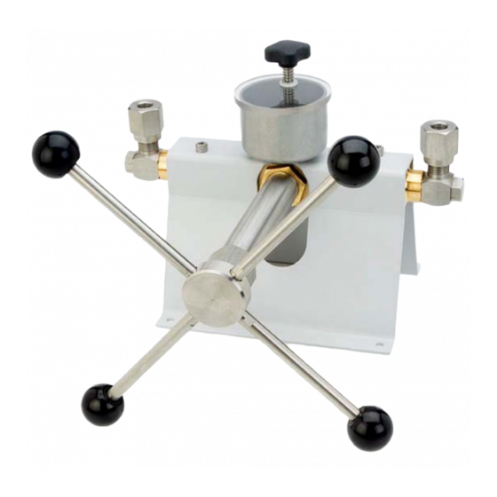
- Page 1 GE Sensing Models: 5514; 5514-V & 5514-EP Hydraulic Comparison Test Pump User’s Manual imagination at work...
- Page 2 HYDRAULIC COMPARISON TEST PUMP MODELS: 5514; 5514-V & 5514-EP USER’S MANUAL GE SENSING 10311 WESTPARK DRIVE HOUSTON, TEXAS 77042 (713) 975 0547 FAX: (713) 975 6338 Release: 5514M-1D01 Revision: B Date: 11/07/06...
-
Page 3: Warranty
WARRANTY GE Sensing warrants its products to conform to or exceed the specifications as set forth in its catalogs in use at the time of sale and reserves the right, at its own discretion, without notice and without making similar changes in articles previously manufactured, to make changes in materials, designs, finish, or specifications. -
Page 4: Revision Notice
REVISION NOTICE RELEASE DATE OF REV. DESCRIPTION NUMBER RELEASE 5514M-1D01 08/18/06 Original release per DC/RO 25178 5514M-1D01 11/07/06 Model numbers modified per DC/RO 25272... -
Page 5: Safety Summary
SAFETY SUMMARY The following are general safety precautions that are not related to any specific procedures and do not appear elsewhere in this publication. These are recommended precautions that personnel must understand and apply during equipment operation and maintenance to ensure safety and health and protection of property. -
Page 6: Table Of Contents
TABLE OF CONTENTS WARRANTY ..................................ii COPYRIGHT NOTICE ..............................ii DISCLAIMER ................................... ii TRADEMARK NOTICE ..............................ii REVISION NOTICE ..............................iii SAFETY SUMMARY ..............................iv COMPRESSED LIQUID .............................. iv PERSONAL PROTECTIVE EQUIPMENT ......................iv TABLE OF CONTENTS ..............................v LIST OF FIGURES ................................. vi PREPARATION ............................ -
Page 7: Preparation
Nitrile; use of solvents, fuel oils, brake fluids or other, similar aggressive fluids can damage the seals. The table below details the two alternative versions of this instrument, which offer increased compatibility with other fluids. Model O Rings 5514 Nitrile 5514-V Viton 5514-EP Ethylene Propylene Rotate reservoir dust cover through ½... - Page 8 THIS PAGE INTENTIONALLY LEFT BLANK PREPARATION...
-
Page 9: Connections
SECTION 2.0 CONNECTIONS Fit the device under test (DUT) to the test port using the method described below: IMPORTANT Ensure that all devices are internally clean and free from contamination before connecting to the tester. Particle contamination can damage the sensitive piston assemblies, valve seats and screw pump. -
Page 10: Figure 2-2A Making Pressure Connections
NOTE: The thread on the test port, and the lower part of the gauge adapters is LEFT- HANDED. The following procedure details the correct method for mounting devices using these adapters: - 1. Screw the appropriate gauge adapter fully on to the instrument to be tested. 2. -
Page 11: Figure 2-2B Making Pressure Connections
3. To adjust the position to face forward, hold the gauge adapter and turn the instrument COUNTER-CLOCKWISE, so that it faces forward. 4. Hold the instrument steady, whilst turning the gauge adapter COUNTER- CLOCKWISE until it pulls down onto the O-ring. -
Page 13: Operation
SECTION 3.0 OPERATION Priming: Open reservoir valve (13) one turn counter-clockwise and turn screw press fully in. Close* valve (13) and turn screw press fully out. Open valve and turn screw press fully in. Note: During this operation, bubbles may appear in the reservoir, as trapped air is expelled. - Page 14 THIS PAGE INTENTIONALLY LEFT BLANK PRIMING...
-
Page 15: Maintenance & Servicing
SECTION 4.0 MAINTENANCE & SERVICING The Figures on the following pages detail the components of each assembly, together with the relevant part numbers. Where “ASSY” appears as a part number, this indicates that this particular component is associated with other components in an assembly for replacement purposes. - Page 16 COMPLETE DISASSEMBLY 4.2.1 Remove the screw press assembly as described above. 4.2.2 Unscrew and remove valve stem (13), taking care not to lose spring (12) and nylon washer (11). 4.2.3 Remove reservoir cover (10). 4.2.4 Unscrew locknut (9), and remove reservoir (8). 4.2.5 Unscrew valve body (6), taking care not to lose bonded seal (7) or O ring (5).
-
Page 19: Figure 4-3 Parts List
ITEM DESCRIPTION PART 5514 5514-V 5514-EP BANJO BOLT P101230 O RING 54-700-14 P103614 P109706 BANJO TEST PORT P101226 O RING P101801 P103606 P109703 O RING 54-700-12 54-703-12 P109705 VALVE BODY SDW5790 BONDED SEAL P101211 P109740 P109716 RESERVOIR P103647 LOCKNUT P101206... - Page 20 THIS PAGE INTENTIONALLY LEFT BLANK MAINTENANCE & SERVICING...
- Page 21 SECTION 5.0 ANCILLARY EQUIPMENT ANGLE ADAPTER, Model 5543 To calibrate gauges with the pressure connection on the rear (e.g. panel-mount gauges) in their correct position, an angle adapter should be used. The angle adapter fits directly onto the test station, converting it through 90 degrees, allowing the standard adapters to be used.
- Page 22 THIS PAGE INTENTIONALLY LEFT BLANK ANCILLARY EQUIPMENT...
- Page 23 U.S.A. 10311 Westpark Drive Houston, TX 77042 T 713 975 0547 F 713 975 6338 imagination at work 5514M-1D01, Revision B November 7, 2006...