Table of Contents

Related Manuals for Iridium NAL SHOUT ns


Summary of Contents for Iridium NAL SHOUT ns
- Page 1 451-01037-001D SHOUT ns/nsx User Guide Version D March 29, 2022 Copyright © 2021 by NAL Research Corporation 11100 Endeavor Ct., Suite 300 Powered by Manassas, Virginia 20109 USA Phone: 703-392-1136 Email: contact@nalresearch.com...
- Page 2 Product (including hardware, software and/or firmware) and/or the Iridium satellite, or arising out of or in connection with the ability or inability to use the Product (including hardware, software and/or firmware) and/or the Iridium satellite to the fullest extent these damages may be disclaimed by law and whether advised of the possibilities of such damages.
- Page 3 SHOUT ns/nsx User Guide Version D EVISION ISTORY Revision Date Description 02/05/2019 Initial version Editorial and format updates; added reference documents; and 07/12/2019 sections for Quick Start User Guide, SHOUT Android App; and NAL Vue Management Tool. Updated to new template 03/17/2022 Formal release 03/29/2022 Added SHOUT nsx device...
- Page 4 SHOUT ns/nsx User Guide Version D EFERENCE OCUMENTS The latest revisions of the NAL documents are available from the NAL Research website at https://www.nalresearch.com/support/documentation-downloads/. Reference Title Revision/Date Revision 1.0.5, AT Commands for Model SHOUT ns 23 March 2018 Revision 3, NAL GPS Report Version 6 Format 26 September 2018 Version 1.7...
-
Page 5: Table Of Contents
Prepare Device ........................22 Start Device ......................... 22 Charge Device ........................23 Device GPS Reception and Iridium Registration ..............23 Configure the SHOUT ns with SatTerm ................23 Pair Device Bluetooth with the SHOUT App ............... 25 AT Command Mode ......................25 Important Features ...................... - Page 6 Users ..........................75 Technical Support ......................77 Appendix A: Standards Compliance ..................78 Appendix B: Export Compliance ................... 79 Appendix C: The Iridium Network ..................80 Iridium Network Data Capabilities ....................81 Dial-Up Data Service ........................82 Document Number: 451-01037-001D...
- Page 7 Short Messaging Service (SMS) ..................... 85 Iridium Geolocation ........................85 Appendix D: SHOUT ns Design Specifications ............... 87 D.1: Mechanical Specifications ..................... 87 D.2 Iridium RF Specifications ......................87 D.3 GPS Specifications ........................87 D.4 Bluetooth RF Specifications ....................88 D.5 Electrical Specifications ......................88 D.6 Environmental Specifications ....................
- Page 8 SHOUT ns/nsx User Guide Version D ABLE OF IGURES Figure 1: SHOUT ns/nsx Buttons and Indicators ................16 Figure 2: SHOUT ns Accessories ....................16 Figure 3: Control Buttons and Status LEDs on the SHOUT ns Front Face ........18 Figure 4: Position of USB Connector .....................
- Page 9 SHOUT ns/nsx User Guide Version D Figure 32: NAL Vue Messaging Window ..................75 Figure 33: Iridium Network Major Components ................80 Figure 34: Iridium Network Data Capabilities ................82 Figure 35: Iridium Dial-Up Data Service ..................83 Figure 36: SHOUT ns Mechanical Drawing ................... 90 Figure 37: SHOUT nsx Mechanical Drawing ..................
- Page 10 SHOUT ns/nsx User Guide Version D ABLE OF ABLES Table 1: Description of LED States ....................18 Table 2: Pin Assignments for the SHOUT ns USB Connector ............20 Table 3: Status Icons ........................64 Document Number: 451-01037-001D 10 of 91...
- Page 11 SHOUT ns/nsx User Guide Version D CRONYM ABS ......Acrylonitrile butadiene styrene AES ......Advanced Encryption Standard API ......Application programming interface AT .......Attention BIS ......Bureau of Industry and Security BIS ......Bureau of Industry and Security BLE ......Bluetooth Low Energy CE .......Conformité Européenne CEP ......Circular Error Probable CFR ......Code of Federal Regulations CSV ......Comma-separated values...
- Page 12 IC ........Industry Canada ID ........Static Identifier IMEI ......International Mobile Equipment Identification I/O ......Input/Output IP ........Internet Protocol ISP .......Internet Service Provider ISU ......Iridium Subscriber Unit JSON ......JavaScript Object Notation LED ......Light Emitting Diode Li-ion ......Lithium-ion LNA ......Low-Noise Amplifier LP ........Low Power LP ........Low Power...
- Page 13 SHOUT ns/nsx User Guide Version D SBAS ......Satellite-Based Augmentation System SBD ......Short Burst Data SMA ......SubMiniature version A SMS ......Short Message Service TBR ......Time-Between-Reports TCP ......Transmission Control Protocol TDD ......Time Division Duplex TDMA ......Time-Division Multiple Access TTKT ......Time To Keep Trying TTL ......Transistor–Transistor Logic USB ......Universal Serial Bus UTC ......Coordinated Universal Time...
-
Page 14: Introduction
The SHOUT ns is a pocket-sized, low-cost, low-power, Iridium satellite network tracking device. It is designed to relay, via the Iridium satellite network, Global Positioning System (GPS) location data and other critical data, such as emergency messages, geofence data, and callouts from the device, and text messages from the NAL SHOUT smartphone app. -
Page 15: Device Description
SatTerm application. The six Light Emitting Diodes (LEDs) provide the status of power state, battery charging status, GPS fix, Bluetooth connection status, report transmission status, and Iridium connection status to the user. Using the Power and Bluetooth buttons, activates the emergency/911 mode to send an emergency message with an increased reporting rate. For detailed information on the emergency/911 mode, refer to section 2.3. -
Page 16: Accessories
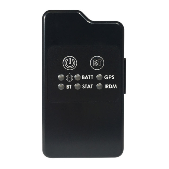
SHOUT ns/nsx User Guide Version D Figure 1: SHOUT ns/nsx Buttons and Indicators Note: The buttons and indicators on the SHOUT nsx are the same as those noted on the SHOUT ns. CCESSORIES AC Wall Adapter USB-A to USB Micro-B Cable Figure 2: SHOUT ns Accessories Document Number: 451-01037-001D 16 of 91... -
Page 17: User Interfaces
SHOUT ns/nsx User Guide Version D NTERFACES OWER UTTON The SHOUT ns has a single power ON/OFF button. The SHOUT ns can be turned off and on again by momentarily holding down the Power button for two seconds and releasing it. If the device is sleeping, briefly pressing the Power button turns the SHOUT ns on for 10 seconds. -
Page 18: Status Leds
The SHOUT ns has six status LEDs, as shown in Figure 3, which include: power , battery level (BATT), GPS fix (GPS), Bluetooth state (BT), transmission status (STAT), and Iridium signal (IRDM). They provide a quick visual check to ensure proper operations. Each LED can be enabled and disabled through a setting in the general configuration profile (^LEDS) (see section 5.2.2.1 General Profile Settings). - Page 19 5 seconds for normal mode to once every 2.5 seconds for emergency mode. Upon Charger Connection: When power is on*, the battery, GPS, Iridium, and status LEDs blink in a clockwise sequence for 3 seconds when power is applied.
-
Page 20: Usb Port
SHOUT ns/nsx User Guide Version D USB P Figure 4: Position of USB Connector The USB connector on the SHOUT ns is a USB Micro-B receptacle located on the right of the chassis, as shown in Figure 4. This connector has a rubber O-ring sealed cover required to achieve the IP67 rating of the device. -
Page 21: Dc Power Inputs
SHOUT ns/nsx User Guide Version D SatTerm graphical user interface (GUI) software to configure the SHOUT ns instead of trying to memorize various AT commands. The latest version of this software can be downloaded from the NAL Research website (https://www.nalresearch.com/support/documentation- downloads/). -
Page 22: Quick Start User Guide
REPARE EVICE Prior to using the SHOUT ns, first purchase airtime from NAL Research or from any Iridium- certified airtime reseller. An airtime reseller must register the SHOUT ns IMEI number to “point” to a Network Operation Center (NOC) server. This section explains how to quickly set up the SHOUT ns as a tracking device. -
Page 23: Charge Device
Plug the wall charger into a 115 VAC power source. Confirm that when the wall charger is plugged in and power is applied to the SHOUT ns USB port, the battery, GPS, Iridium, and status LEDs blink in clockwise sequence for 3 seconds. Let the SHOUT ns charge for several hours or until the BATT LED changes to steady illumination. - Page 24 SHOUT ns/nsx User Guide Version D If you want to change these default settings, the SHOUT ns supports a Micro-USB connection to a computer with SatTerm software (or any terminal emulator software) to configure its operating profile using NAL Research’s defined AT commands. Find these AT commands in the manual “AT Commands for Model SHOUT ns”...
-
Page 25: Pair Device Bluetooth With The Shout App
SHOUT ns/nsx User Guide Version D SHOUT A EVICE LUETOOTH WITH THE After the NAL SHOUT Android app has been downloaded to the desired device, proceed to pair the device with the SHOUT ns. To pair a device such as a smartphone or tablet with the SHOUT ns for the first time, a connection to the USB interface of a PC is required to use the SatTerm PC-based terminal emulation application (see section 5.2 Using SatTerm). - Page 26 SHOUT ns/nsx User Guide Version D sequence three pluses, “+++”. If “+++” is not entered within 10 seconds, the SHOUT ns goes back to sleep. See section 4.2 Modes of Operation for a more detailed description of the command mode and see the NAL document “AT Commands for Model SHOUT ns” [1] for a full list of the AT command capabilities.
-
Page 27: Important Features
OMMUNICATION INKS The SHOUT ns uses the Iridium network to send its location reports. To use Iridium service, the International Mobile Equipment Identification (IMEI) number must be activated with an SBD service plan through an authorized Iridium reseller. When an IMEI is provisioned for service, up to five SBD delivery destinations can be specified. - Page 28 Both of these options also directly affect the SHOUT ns power consumption. For supporting message-receiving scenarios, referred to as “Callable,” the SHOUT ns Iridium modem can be set to be on at all times by using the ^CAL command. This configuration prevents the SHOUT ns device from sleeping and greatly increases power consumption.
-
Page 29: Call-Outs And Turn-On Delay
SHOUT ns/nsx User Guide Version D tracking mode starts, the tracking profile for normal tracking is loaded, specified by the "Tracking Profile Normal" (^TPN) setting. When the emergency mode is triggered, tracking mode switches to using the tracking profile for emergency tracking, specified by the "Tracking Profile Emergency"... -
Page 30: Motion Detection
SHOUT ns/nsx User Guide Version D addition, geofences can be configured to turn off the Iridium modem for regions that require radio silence. OTION ETECTION The SHOUT ns has a built-in sensor that can reliably detect motion. It is an omnidirectional movement sensor and functions regardless of how the SHOUT ns is mounted or aligned. - Page 31 SHOUT ns/nsx User Guide Version D applications that can be used to compose and transmit remote updates: Server for Trackers and Remote Configure. These programs can be downloaded from the NAL Research’s website (https://www.nalresearch.com/support/documentation-downloads/). Refer to the software applications for the list of remotely configurable parameters. Document Number: 451-01037-001D 31 of 91...
-
Page 32: Configure The Shout Ns
SHOUT ns/nsx User Guide Version D SHOUT ONFIGURE THE The SHOUT ns can be configured in one of three ways from a computer connected to the SHOUT ns USB port: 1) manually through the SatTerm PC-based application (see section 5.2 Using SatTerm), 2) through a file download using SatTerm (see section 5.2.2.4 Configure Settings), and 3) via AT commands (see section 4.2.1 Command Mode). -
Page 33: Using Satterm
SHOUT ns/nsx User Guide Version D in tracking mode. Instead, tracking mode loads the stored tracking profiles directly based on the current state. o At power-up, tracking profile 0 is always loaded into the “active” tracking profile. However, after power-up, you can load any of the stored tracking profiles using the soft reset AT command ZT. -
Page 34: Figure 5: Port Properties Window Option
Connect Using dropdown list and select USB. Select the desired SHOUT ns from the USB Devices Connected box. If multiple SHOUT ns devices are attached, they can be differentiated by the IMEI number of the internal Iridium modem. Figure 5: Port Properties Window Option Document Number: 451-01037-001D... -
Page 35: Figure 6: Bluetooth Port Properties Window Unpaired
SHOUT ns/nsx User Guide Version D 5.2.1.2 ONNECTING WITH LUETOOTH This section describes how to connect and pair the SHOUT ns to SatTerm via Bluetooth. Connecting to Bluetooth is also done through the Port Properties window. The Bluetooth port properties window (see Figure 6) has several buttons, which function as follows: ... -
Page 36: Figure 7: Bluetooth Port Properties Paired
SHOUT ns/nsx User Guide Version D 4. Attach the SHOUT ns to the computer’s USB port. The SHOUT ns must be connected to USB for first-time pairing. 5. Use the Options > Properties menu to configure the communications port settings (see Figure 5). -
Page 37: Configure Window
SHOUT ns/nsx User Guide Version D 5.2.2 ONFIGURE INDOW The SatTerm Configure Window option allows users to set up the profiles described in section 5.1 Profile Descriptions. After the hardware setup is completed using the steps above, select Options > Configure Windows to configure the specific settings for the SHOUT ns (see Figure 8). -
Page 38: Figure 9: General Profile Window With Tracking Tab
SHOUT ns/nsx User Guide Version D Figure 9: General Profile Window with Tracking Tab 5.2.2.1.1 RACKING Tracking offers five settings, as shown in Figure 9: Remote Message Format, GPS Always ON, Start-Up Mode, Tracking Log, and Max. Queued Reports. Remote Message Format: Sets the format of the messages that are sent from the SHOUT ns to the recipient. - Page 39 This setting applies only if Queue Failed Reports, Queue Restricted Reports, or both are set (see section 5.2.2.2 Tracking Profile Settings). A restricted report is a report that attempts to send while the Iridium link is configured to be disabled. For example, if Iridium is disabled in a certain geographic area by a geofence, any reports that attempt to send while in the geofence would be considered a restricted report.
-
Page 40: Figure 10: General Profile Window With Motion Tab
SHOUT ns/nsx User Guide Version D Failed reports are reports that are unable to send after the specified Time to Keep Trying value (see section 5.2.2.2 Tracking Profile Settings). o When the number of queued reports reaches its maximum number, the oldest queued reports are overwritten. -
Page 41: Figure 11: Motion Detection Example
SHOUT ns/nsx User Guide Version D sensor. Figure 11 illustrates the algorithm with a window count of 3, window duration of 1 minute, and a sensitivity of 2 TTL pulses. Note: The motion detection algorithm starts over whenever the device receives a remote update. - Page 42 SHOUT ns/nsx User Guide Version D o The AT command associated with this setting is ^MSB. Sensitivity: Specifies the minimum number of motion sensor TTL pulses that must be detected in order to satisfy a single motion detection window for the motion detection algorithm.
-
Page 43: Figure 13: General Profile Window With Led Tab
Iridium LED: Sets whether to display the Iridium (IRDM) LED. When enabled, the Iridium LED stays solid when the Iridium signal strength is between 3–5 bars, blinks... - Page 44 SHOUT ns/nsx User Guide Version D when the Iridium signal strength is between 1–2 bars, and stays off when the Iridium signal strength is at 0 bars. GPS LED: Sets whether to display the GPS LED. When enabled, the GPS LED stays solid when there is a valid GPS position fix, blinks when there is 2-D fix or using dead reckoning, and stays off when unable to obtain a position fix.
-
Page 45: Figure 14: General Profile Window With Gps Tab
SHOUT ns/nsx User Guide Version D Figure 14: General Profile Window with GPS Tab Invalid Course Value: This value is sent in GPS reports to indicate an invalid course when the GPS receiver is unable to determine the course. o The AT command associated with this setting is ^ICV. -
Page 46: Figure 15: General Profile Window With Miscellaneous Tab
SHOUT ns/nsx User Guide Version D 5.2.2.1.5 ISCELLANEOUS The Miscellaneous tab provides seven settings as shown in Figure 15: Successful Send Required for State Change, Startup Information, Bluetooth Power, Normal Tracking Profile, Emergency Tracking Profile, Power Up Time Refresh Frequency, and Remote Update Time Check. Figure 15: General Profile Window with Miscellaneous Tab ... - Page 47 SHOUT ns/nsx User Guide Version D Startup Information: Hides/shows the text displayed when the device is turned on (copyright, model number, etc.), which is echoed to the SHOUT ns device’s USB serial port. o The AT command associated with this setting is ^SSI. ...
-
Page 48: Figure 16: Tracking Profile Window With Tracking Tab
The Tracking tab has eight settings: Report Flood, Blocked Invalid Reports, Queue Failed Reports, Queue Restricted Reports, Motion Enabled, Callable, Skip Reporting when Stationary, and Iridium Allowed. Report Flood: Sets the number of tracking reports that are to be transmitted continuously when first entering tracking mode and when the tracking mode changes (for example, from normal to emergency). - Page 49 A report is considered restricted when the Iridium link has been disabled. o For example, if Iridium is disabled in a certain geographic area by a geofence, tracking reports collected while in the geofence would be considered restricted reports.
- Page 50 Send While Stationary cycles each time a new sphere is established. o The AT command associated with this setting is ^SPSR. Iridium Allowed: Enables/disables the Iridium link. Refer to the Queue Restricted Reports option (section ) for additional details.
-
Page 51: Figure 17: Tracking Profile Window With Geofence Frequency Tab
SHOUT ns/nsx User Guide Version D Figure 17: Tracking Profile Window with Geofence Frequency Tab Geofence Check Frequency: Sets the maximum time between position updates to check if the device is in a geofence. If a valid GPS position is received before the next check, the countdown to the next check is restarted. -
Page 52: Figure 18: Interval Tab In Tracking Profile Window With Standard And Motion Tabs
SHOUT ns/nsx User Guide Version D Figure 18: Interval Tab in Tracking Profile Window with Standard and Motion Tabs Use Alternate Interval for Motion: When this setting is set to Yes, the SHOUT ns uses alternate Time Between Reports, Time To Keep Trying, and Delayed First Report settings while in motion. - Page 53 SHOUT ns/nsx User Guide Version D Only Once forces the SHOUT ns to send only once per report cycle regardless of whether the tracking report was successfully transmitted or not. Until Next Report forces the SHOUT ns to retry sending a tracking report up to the next reporting cycle if there is no successful transmission.
-
Page 54: Figure 19: Other Profile Window With Miscellaneous Tab
Identifier in Reports: Sets an additional identifier of up to 50 characters that is included in Type 3, Type 4, and Type 5 tracking reports. Keep the identifier short to reduce airtime cost, especially when on the Iridium link. o The AT command associated with this setting is ^ID. -
Page 55: Figure 20: Encryption Tab And Change Encryption Settings Window
SHOUT ns/nsx User Guide Version D 5.2.2.3.2 NCRYPTION The SHOUT ns can send and receive data in AES 256-bit encrypted format. Figure 20 displays the SatTerm encryption setting window that opens after selecting the Change button in the Encryption tab. Options include changing the Crypto Officer Password, enabling or disabling encryption, and setting the encryption and decryption keys. - Page 56 SHOUT ns/nsx User Guide Version D After the default password has been changed, set the encryption and decryption keys in order to use encryption. 1. In the Change Encryption Settings window, select Use under Use Encryption. 2. Select the Encryption Key checkbox and enter the key twice. 3.
-
Page 57: Geofencing
SHOUT ns/nsx User Guide Version D Figure 21: Successful Update Made Window 5.2.3 EOFENCING The SHOUT ns can utilize location information from its GPS receiver to determine whether it has entered or exited the bounds of preconfigured geofences. A geofence is a set of connected latitude and longitude coordinates that defines a region or zone. -
Page 58: Figure 22: Geofences Window
SHOUT ns/nsx User Guide Version D The ID column indicates the identifier assigned to the geofence. This identifier is used to reference the geofence when the SHOUT ns sends arrival and departure notices and when updating geofence parameters via AT commands or remote updates. ... -
Page 59: Figure 23: Create/Edit Geofence Window
SHOUT ns/nsx User Guide Version D At the bottom of the Geofences window is a set of buttons. Descriptions of the buttons are as follows: Configure: Selecting the Configure button saves the list of geofences on the SHOUT ns. ... -
Page 60: Call Out
SHOUT ns/nsx User Guide Version D o The minimum number of points in a geofence is 3 and maximum number of points is 50. Note: The Create Geofence option utilizes Google Maps. An internet connection is required for the map to appear. ... -
Page 61: Figure 24: Callout Form Window
SHOUT ns/nsx User Guide Version D Figure 24: Callout Form Window Document Number: 451-01037-001D 61 of 91... -
Page 62: Nal Shout Android App Overview
The next segment is the status bar, which provides an overview of the SHOUT ns status (Iridium network connection, GPS signal strength, battery life/charging status, text message status, etc.), as well as an array of icons for the various SHOUT app functions. -
Page 63: Title Bar
SHOUT ns/nsx User Guide Version D The last segment is the bottom dock. Like an Android smart phone, this menu area is always present on every screen and allows a quick change to a new menu area when desired. Title Bar Status Bar Menu / Function Area... - Page 64 SHOUT ns/nsx User Guide Version D Table 3: Status Icons Denotes the Iridium transceiver is off. To preserve battery life, the Iridium transceiver is only turned on when transmitting a message or position report; thus, a diagonal line is drawn over the symbol when off.
-
Page 65: Menu Functional Area
SHOUT ns/nsx User Guide Version D Table 3: Status Icons Denotes Mailbox Check is on when the symbol is bright white. The symbol turns dimmed gray when Mailbox Check is off. Denotes Tracking (standard tracking, geofence tracking, etc.) is on when the symbol is bright white. -
Page 66: Tracking Menu
Some menus, such as Geofences and Call Out, require using SatTerm to configure parameters beforehand. For these options, refer to section 5.2 Using SatTerm for more details. This menu has the following submenu items: Report Rate Format Link (Iridium) Geofences Brevity Block Report Call Out... -
Page 67: Utilities Menu
The Utilities menu, shown in Figure 28, provides five options used mainly to check for proper hardware operation and network setup. These utilities can be useful when trying to troubleshoot certain problems with the device. This menu has the following submenu items: Check GPS Check Iridium Test Report Check-In Waypoints... -
Page 68: Use Nal Vue With Shout Ns
SHOUT ns/nsx User Guide Version D NAL VUE SHOUT WITH VERVIEW NAL Vue is a web-based locating, tracking, and communication management system that provides your team with situational awareness and control to make timely and effective mission decisions. NAL Vue is an integrated system bringing satellite, GSM, and other data together into a single and simple-to-manage display and control platform. -
Page 69: Asset Management Tools
SHOUT ns/nsx User Guide Version D Figure 30: NAL Vue Home Map/Asset Window 7.2.2 SSET ANAGEMENT OOLS Full create, read, update, and delete (CRUD) functionality for assets allows administrators and users to gather data in near real time, and under most circumstances, act upon that data without needing to leave the portal. -
Page 70: Figure 31: Nal Vue Add Asset Window
SHOUT ns/nsx User Guide Version D to see. Additionally, the user can switch between enabling and disabling various map layers on the view. Layers on the map are ways for specific organizations to get more value out of the interface, particularly maritime industries, which has its own map layer available by default. - Page 71 SHOUT ns/nsx User Guide Version D While adding assets, managers can also associate the asset with any number of groups or users so that the asset is visible and sorted within those groups immediately after it has been added to the system. There are a number of complex settings that can also be configured by the asset manager, including how to display it on the map.
-
Page 72: Alerts
SHOUT ns/nsx User Guide Version D 7.2.3 LERTS NAL Vue can help asset managers keep track of everything including service reminders and maintenance requirements for each of the assets in the system, whether the alerts are set to occur by intervals (i.e., a certain amount of time or usage) or by specific milestones. NAL Vue can use any of its collected data points to alert managers if one if its assets is in need of attention. -
Page 73: Settings And Preferences
SHOUT ns/nsx User Guide Version D host of report types ranging from activity reports, which are detailed lists of all information gained from an asset, to more specific reports like geofence dwell reports, which identify how long an asset has been within a specific area. In addition to asset-related reports, administrators can also generate reports for NAL Vue users so that they can track the IP address, activity log, and session data for all activity in the system within a given time frame. - Page 74 SHOUT ns/nsx User Guide Version D layers and map views on the Assets tab. Most of the map layers are provided by the National Oceanic and Atmospheric Association (NOAA), but clients also have the capability to add their own. The map views are provided by a third-party service called Mapbox®. It is important to note that in some cases the tile images by Mapbox can be improved, and more detailed visuals or more recent visuals of a given area can be obtained for a fee.
-
Page 75: Users
SHOUT ns/nsx User Guide Version D Figure 32: NAL Vue Messaging Window For emergency services, this can be employed to make persons aware of how to respond to threats or natural disasters; for fleet managers, messages could include important information about expected delays, route guidance, modifications to the existing plan, or additional waypoints. - Page 76 SHOUT ns/nsx User Guide Version D The anonymous user is not technically a user on NAL Vue. This user profile gives organizations the ability to make NAL Vue data (i.e., the location and behavior of an asset or asset group) available to people outside of the organization through a URL link. For more details regarding NAL Vue, see the NAL document “NAL Vue User Guide”...
-
Page 77: Technical Support
SHOUT ns/nsx User Guide Version D ECHNICAL UPPORT For technical support, please contact us at: Phone: 703-392-1136, x203 Fax: 703-392-6795 Email: contact@nalresearch.com Technical documents are also available to download on NAL Research’s website www.nalresearch.com in the Support > Documentation & Downloads section. Document Number: 451-01037-001D 77 of 91... -
Page 78: Appendix A: Standards Compliance
SHOUT ns/nsx User Guide Version D A: S PPENDIX TANDARDS OMPLIANCE The 9603 transceiver inside the SHOUT ns is designed to meet the regulatory requirements for approval for FCC, Canada, and CE, assuming an antenna with a gain of approximately 3 dBiC and adequate shielding. -
Page 79: Appendix B: Export Compliance
SHOUT ns/nsx User Guide Version D B: E PPENDIX XPORT OMPLIANCE The SHOUT ns is controlled by the export laws and regulations of the United States of America (USA). It is the policy of NAL Research to fully comply with all U.S. export and economic sanction laws and regulations. -
Page 80: Appendix C: The Iridium Network
Figure 33: Iridium Network Major Components The Iridium network is designed to operate in the band of 1616.0 to 1626.5 MHz, although the exact frequencies used depend on the local regulating authorities and issued licenses in any particular region. -
Page 81: Iridium Network Data Capabilities
1,100 simultaneous circuits. The Iridium network uses a time division duplex (TDD) method and transmits and receives in an allotted time window within the frame structure. Since the system is TDD, the ISU transmit and receive in the same frequency band. -
Page 82: Dial-Up Data Service
(or modem training) can range from 15 to 30 seconds. For an Iridium-to-Iridium call, dial-up data service offers an additional option known as Data After Voice (DAV). Similar to a voice call, a DAV call is routed directly from one Iridium modem to another Iridium modem without going through the gateway. -
Page 83: Direct Internet Connection
The modem at the Iridium gateway then dials into and connects to another modem at the other end. Figure 35 illustrates how an Iridium dial-up data service call is routed. The handshaking and protocols established between the modems are independent of the Iridium network. -
Page 84: Rudics Data
Iridium satellite network. When an Iridium modem places a call to the RUDICS Server located at the Iridium gateway, the RUDICS server connects the call to a predefined IP address, allowing an end-to-end IP connection between the host application and the Iridium modem. -
Page 85: Short Messaging Service (Sms)
ESSAGING ERVICE SMS is a mechanism to deliver short data messages over the Iridium satellite network to the NIPRNet/internet. Iridium SMS incorporates a subset of the GSM SMS features. Each SMS message can be up to 160 text characters (7-bit coded) in length. The text characters are based on a 7-bit alphabet, which is encoded and transmitted as 8-bit data, hence the 140 octet (byte) maximum message size. - Page 86 The Iridium network can locate an ISU to within 10 km only about 78% of the time. The so- called error ellipse can have a large eccentricity with the major axis oriented in the azimuth dimension and the minor axis oriented in the radial dimension.
-
Page 87: Appendix D: Shout Ns Design Specifications
Weight – SHOUT nsx: ..........~131 g (~4.6 ounces) Enclosure Material: ............Hard ABS plastic Interface Connector: ..........USB Micro-B receptacle Antennas: ..............Embedded Iridium, GPS, and Bluetooth ON/OFF button: ............Dome push button Bluetooth Switch: ............Dome push button Status LED Displays: ...........Power, Battery, GPS, Bluetooth, message sent status, Iridium D.2 I... -
Page 88: Bluetooth Rf Specifications
SHOUT ns/nsx User Guide Version D Update Rate: ..............4 Hz Accuracy: ..............Position: 2.5 meters (8.2 feet) CEP Position SBAS: 2.0 meters (6.6 feet) CEP Acquisition (typical): ..........Hot starts: 1 second Aided starts: 2 seconds Cold starts: 29 seconds Sensitivity: ..............Tracking: –166 dBm Reacquisition: –160 dBm Cold starts: –148 dBm Operational Limits: .............Altitude: 50,000 meters (164,000 feet) -
Page 89: Environmental Specifications
SHOUT ns/nsx User Guide Version D Current in Between Reports (sleep): ......Less than 110 μA @ +3.7 V Note: The average current drawn during transmission may vary depending on the field of view between the SHOUT ns antenna and the Iridium satellite. D.6 E NVIRONMENTAL PECIFICATIONS Design Operating Temperature Range: .....–20°C to +60°C (–4°F to +140°F) -
Page 90: Appendix E: Mechanical Drawings
SHOUT ns User Guide Version D E: M PPENDIX ECHANICAL RAWINGS E.1 SHOUT ECHANICAL RAWING Figure 36: SHOUT ns Mechanical Drawing Document Number: 451-01001.B.1 90 of 91... -
Page 91: Shout Nsx Mechanical Drawing
SHOUT ns/nsx User Guide Version D E.2 SHOUT ECHANICAL RAWING Figure 37: SHOUT nsx Mechanical Drawing Document Number: 451-01037-001C 91 of 91...