Table of Contents

Related Manuals for Iridium SHOUT ns


Summary of Contents for Iridium SHOUT ns
- Page 1 451-01001.B GENERAL DESCRIPTION OF MODEL SHOUT ns Revision B July 12, 2019 Copyright © 2019 by NAL Research Corporation 9385 Discovery Boulevard, Suite 300 Manassas, Virginia 20109 USA Phone: 703-392-1136 x203 E-mail: contact@nalresearch.com...
-
Page 2: Legal Disclaimer And Conditions Of Use
Product (including hardware, software and/or firmware) and/or the Iridium satellite services, or arising out of or in connection with the ability or inability to use the Product (including hardware, software and/or firmware) and/or the Iridium satellite services to the fullest extent these damages may be disclaimed by law and whether advised of the possibilities of such damages. -
Page 3: Revision History
The latest revision of these documents are available from the NAL Research website at (http://www.nalresearch.com/Downloads.html). Reference Title Revision / Date Revision 1.0.5, AT Commands for Model SHOUT ns 23 March 2018 Revision 3, NAL GPS Report Version 6 Format 26 September 2018 PECOS Message Definition Specification, 200907- Version 1.7... -
Page 4: Table Of Contents
Device Start-up ................... 19 Device Charging ..................19 Device GPS reception and Iridium Registration ..........20 Configuring the SHOUT ns with the SatTerm Application ........20 Device Bluetooth pairing with the SHOUT Android App ........21 AT Command Mode ..................22 IMPORTANT FEATURES .............. - Page 5 Texting Menu ....................59 Tracking Menu ..................... 59 Utilities Menu ....................60 Settings Menu ..................... 61 SHOUT NS USE WITH THE NAL VUE MANAGEMENT TOOL ....... 62 Overview ....................62 NAL Vue User Interface ................. 62 8.2.1 Six Core Tabs ................... 62 8.2.2...
- Page 6 C.2.3 Router-based Unrestricted Digital Internetworking Connectivity Solution (RUDICS) ......................... 77 C.2.4 Short-Burst Data (SBD) ................77 C.2.5 Short Messaging Service (SMS) ..............77 C.3 Iridium Geo-Location ..................78 MECHANICAL DRAWING ................79 NAL Research Corporation (451-01001.B)
-
Page 7: Glossary
Ground Global Positioning System Global System for Mobile Communication (Groupe Spécial Mobile) Graphical User Interface Static Identifier IMEI International Mobile Equipment Identification Iridium Subscriber Units Light Emitting Diode Li-Ion Lithium Ion Low Noise Amplifier Low Power Network Operation Center OFAC... - Page 8 Short Burst Data Sub-Miniature Version A Short Message Service Time Division Duplex TDMA Time Division Multiple Access VSWR Voltage Standing Wave Ratio NAL Research Corporation (451-01001.B)
-
Page 9: Purpose
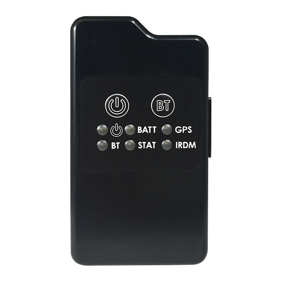
Call Outs. Externally, the SHOUT ns has two buttons and six LEDs to provide the user control and status of the device. The six LEDs provide the status of power state, battery charging status, GPS fix, Bluetooth connection status, report transmission status, and Iridium connection NAL Research Corporation (451-01001.B) - Page 10 USB port can be used to communicate with a laptop for configuration or data collection. The SHOUT ns also has an associated Android app for use with a Bluetooth enabled smartphone or tablet to provide the same functionality as other NAL SHOUT devices with displays.
-
Page 11: General Specifications
Bluetooth Switch: Dome push button Status LED Displays: Power, Battery, GPS, Bluetooth, message sent status, Iridium Figure 1. SHOUT ns Buttons and Indicators. Manuals and Software AC Wall Adapter USB-to-micro USB Cable Figure 2. SHOUT ns Accessories. NAL Research Corporation (451-01001.B) -
Page 12: Iridium Rf Specifications
Dynamics ≤ 4g As long as power is provided to the SHOUT ns, the GPS receiver will provide Real-Time clock functionality and will store ephemeris data in its memory before powering down (sleep between reports). The ephemeris data are valid up to two hours and can be used in future startup to improve time-to-first-fix. -
Page 13: Electrical Specifications
Current in Between Reports (sleep): Less than 110A @ +3.7V NOTE: The average current drawn during transmission may vary depending on the field-of-view between the SHOUT ns antenna and the Iridium satellite. 2.6 Environmental Specifications Design Operating Temperature Range: –4 F to +140 F (–20... -
Page 14: User Interfaces
Emergency / 911 mode is active will also have the Emergency flag set. In order to activate the emergency / 911 mode feature on the SHOUT ns, a four (4) button press sequence must be initiated. This sequence involves alternating between the Power Button (first) and Bluetooth Button for a total of two (2) times each. - Page 15 Each LED can be enabled and disabled through a setting in the general configuration profile (^LEDS) (see Section 6.2.2.1 General Profile Settings). Table 1 below describes the function of each LED. Figure 3. Control Buttons and Status LEDs on the SHOUT ns front face. LABEL NAME...
-
Page 16: Usb Port
Figure 4. Position of USB Connector. The USB connector on model SHOUT ns is a USB micro B receptacle located on the right of the chassis as shown in Figure 4. This connector has a rubber O-ring sealed cover required to achieve the IP67 rating of the device. -
Page 17: Usb Data
USB port. This interface can be used to interface with SatTerm and the NAL SHOUT Android app. To pair a device with the SHOUT ns, an initial connection to the USB interface is required. During the pairing process utilizing SatTerm, the command AT^BTPASS is used to enter the passkey. - Page 18 The Bluetooth interface has a 10-minute idle timer which will turn off the Bluetooth interface when there is no data transfer or it is disconnected for 10 minutes. To keep the interface alive, an AT command such as just “AT” (the SHOUT ns will simply respond with “OK”) should be sent periodically.
-
Page 19: Quick Start User Guide
Remove the SHOUT ns, the wall charger and the USB cable from the packaging. Remove the SHOUT ns USB port cover (see Figure 4) and connect the USB cable USB micro port to the SHOUT ns. Connect the USB-A connector to the wall charger. -
Page 20: Device Gps Reception And Iridium Registration
Plug the wall charger into a 115V AC power source. Confirm that when the wall charger is plugged in and power is applied to the SHOUT ns USB port, the Battery, GPS, Iridium, and Status LEDs blink in clockwise sequence for 3 seconds. Let the SHOUT ns charge for several hours or until the BATT LED changes to steady illumination. -
Page 21: Device Bluetooth Pairing With The Shout Android App
SHOUT ns. To pair an device such as a smartphone or tablet with the SHOUT ns for the first time, a connection to the USB interface of a PC is required to use the SatTerm PC based Terminal Emulation application (see Section 6.2 Using SatTerm). -
Page 22: At Command Mode
SHOUT ns USB interface through a USB cable. For example, the SHOUT ns can be turned off using the AT command ^SHUTDOWN. If the device is sleeping or in low-power in between reporting cycles, pressing the power button will turn the SHOUT ns on for 10 seconds. -
Page 23: Important Features
IP Address, Email, and IMEI. 5.2 Modes of Operation The SHOUT ns is always in one of two modes: (1) Command mode, or (2) Tracking mode. It can be configured to power up in one of these modes. The factory-set ”Start-Up Mode”... - Page 24 The SHOUT ns can operate in a low-power mode whereby the device powers down and sleeps between reports. When operating in low-power mode, the device consumes less than 110A of current during sleep. Tracking may enter the low-power mode while the USB and Bluetooth user interfaces are in use.
-
Page 25: Call-Outs And Power-Up Delay
It is sensitive to both tilt (static acceleration) and vibration (dynamic acceleration). The signal level is fed directly into the SHOUT ns micro-controller to “wake up” the SHOUT ns out of low-power mode when activity is sensed and to transmit location report. The motion... -
Page 26: Encryption
(see Section 6.2.2.1 General Profile Settings). 5.6 Encryption The SHOUT ns can be configured to encrypt/decrypt all transmitted and received data using 256-bit AES encryption. To enable encryption, the user needs to assign a cryptographic administrator for the device who will be responsible for modifying the encryption and decryption keys and setting the device to use encryption (see Section 6.2.2.3 Additional Setup... -
Page 27: Configuring The Shout Ns
6.0 CONFIGURING THE SHOUT NS The SHOUT ns can be configured in one of three ways from a computer connected to the SHOUT ns USB port; 1) manually through the SatTerm PC based application (see Section 6.2 Using SatTerm), 2) through a file download using SatTerm (see Section 6.2.2.4 Configure Settings), and 3) via AT Commands (see Section 5.2.1 Command Mode). -
Page 28: Additional Setup Parameters
Manual for installation instructions). 6.2.1 Connecting SatTerm to the SHOUT ns SatTerm can connect to the SHOUT ns using the USB port or through the Bluetooth link. Each method is detailed in the following two sections. 6.2.1.1 Connecting with USB Follow the steps below first to synchronize communication between the SHOUT ns and a connected USB device. - Page 29 Figure 5. Port Properties Window option. 6.2.1.2 Connecting with Bluetooth This section describes how to connect and pair the SHOUT ns to SatTerm via Bluetooth. Connecting to Bluetooth also is done through the Port Properties. The Bluetooth port properties window (see Figure 6) has several buttons, and the functionality of each are as...
- Page 30 2 seconds. The BT LED should blink, indicating that it is ready for pairing. 4. Attach the SHOUT ns to the computer’s USB port. This is important, as the SHOUT ns must be connected to USB for first time pairing.
-
Page 31: Configure Window
Bluetooth is on and click the refresh button to search for the device again. 7. Next, click on your SHOUT ns device from the Paired Bluetooth list (see Figure 7), and click the OK button to connect. If connect is a successful, the window will close and SatTerm is properly connected to the SHOUT ns. - Page 32 ON, Start-Up Mode, Tracking Log, and Max. Queued Reports. 6.2.2.1.1.1 Remote Message Format This option sets the format of the messages that will be sent from the SHOUT ns to the recipient. Currently available message formats are: NAL Type 3 Same format as on the A3LA trackers.
- Page 33 GPS acquisition and more accurate location information. If the SHOUT ns powers down to sleep while idle, the GPS receiver will also turn off. The AT command associated with this setting is ^GAO.
- Page 34 Options > Tracking Log…. The AT command associated with this setting is ^DLTRK. 6.2.2.1.1.5 Max. Queued Reports This option sets the maximum number of reports that can be queued on the SHOUT ns for re-transmit. This setting applies only if either Queue Failed Reports or Queue Restricted Reports or both are set (see Section 6.2.2.2 Tracking Profile Settings).
- Page 35 Figure 10. General Profile window with Motion tab. When motion detection is enabled, the device will monitor the motion sensor to detect when the device is in motion. To detect the start of motion, an algorithm involving motion detection windows is used. This algorithm succeeds to detect motion when a certain number of contiguous windows are each satisfied by a minimum number of TTL pulses from the motion sensor.
- Page 36 Figure 11. Motion detection example. Once motion has been detected using the motion detection algorithm, the device will be considered in motion and report formats which support motion indication will have the motion indicator set. While in motion, the device will switch to a different algorithm for detecting the end of motion.
- Page 37 6.2.2.1.3 LED Tab For applications where prolonging battery life is essential, the LEDs can be turned OFF using the ^LEDS AT command or the SatTerm LED tab (see Figure 13). The SHOUT ns is shipped with all LEDs set to ON.
- Page 38 This parameter sets whether to display the Iridium “IRDM” LED. When enabled, the Iridium LED stays solid when the Iridium signal strength is between 3–5 bars, blinks when the Iridium signal strength is between 1–2 bars, and stays off when the Iridium signal strength is at 0 bars.
- Page 39 6.2.2.1.4 GPS The GPS tab, shown in Figure 14, offers users the option to configure the GPS receiver and stream NMEA formatted GPS data from the SHOUT ns serial port while in Command, Tracking or both modes. 6.2.2.1.4.1 Invalid Course Value This value is sent in GPS reports to indicate an invalid course when the GPS receiver is unable to determine the course.
- Page 40 For most applications operating below 12 km, the Portable setting is sufficient. Those requiring operation above 12 km should refer to the “AT Commands for Model SHOUT ns” [1] document for detail. The AT command associated with this setting is +PNAV.
- Page 41 Figure 15. General Profile window with Miscellaneous tab. 6.2.2.1.5.1 Successful Send Required for State Change This option restricts the SHOUT ns from changing to a lower priority tracking mode based on whether or not a tracking report has been transmitted. Among the three tracking modes the order of priority is Emergency, Geofence, and then Normal.
- Page 42 GPS receiver timing signal. In the case when the GPS receiver does not yet have a time fix, the SHOUT ns will stay awake for a specified period of time (Allowed GPS Acquisition Time) waiting for a GPS time fix. After which, the SHOUT ns will sleep for another period of time (Power Up Time Refresh Frequency) before retrying to find a time fix.
- Page 43 Tracking tab has eight settings: Report Flood, Blocked Invalid Reports, Queue Failed Reports, Queue Restricted Reports, Motion Enabled, Callable, Skip Reporting when Stationary, and Iridium Allowed. 6.2.2.2.1.1 Report Flood This parameter sets the number of tracking reports that are to be transmitted continuously when first entering Tracking mode and when the tracking mode changes (for example, from Normal to Emergency).
- Page 44 However, the SHOUT ns will consume the most power because the device will never go into sleep mode. When Callable is set to "No", the SHOUT ns puts all its internal circuitry in sleep mode while idle. Any incoming messages or updates from a control center will have to wait until the next reporting cycle (when the RF module wakes up for sending).
- Page 45 While the unit remains in the sphere, report sending skips a specified Cycles to Skip number of report cycles. When the Cycles to Skip value is reached, the SHOUT ns will report for a specified number of Send While Stationary cycles. The process is repeated until the unit leaves the sphere.
- Page 46 This parameter sets the amount of time the geofence check attempts to acquire a GPS position. If the SHOUT ns fails to acquire a position in the time allowed, the geofence check will be aborted and will occur at the next scheduled check or the next time the GPS receiver has a valid position.
- Page 47 Once the GPS fix and signal strength requirements are met, the device will send a report. If the report fails to send, the SHOUT ns will retry until the specified Time To Keep Trying window expires. There are two additional special values for Time To Keep Trying –...
- Page 48 The Identifier in Reports parameter sets an additional identifier of up to 50 characters which will be included in Type 3, Type 4, and Type 5 tracking reports. Users should keep the identifier short to reduce airtime cost especially when on the Iridium link. The AT command associated with this setting is ^ID.
- Page 49 YYYY/MM/DD HH:MM:SS (i.e., 2012/11/30 12:54:23). When in Tracking mode and immediately after power is applied to the SHOUT ns, the device remains in a power-saving sleep mode until the user-specified date and time. At which point, the device enters Tracking mode.
- Page 50 The current Configuration Window settings can be saved to a file, by clicking the “Save” button at the bottom of the Configuration Window. The SHOUT ns can also be configured from an existing *.ncf configuration file. To load an existing *.ncf configuration file into the SHOUT ns, select Options > Configure from File…...
-
Page 51: Geofencing
A SHOUT ns can be configured to send a report when entering or exiting a geofence, and to use a different tracking profile. This gives user the ability to change the behavior of the SHOUT ns based on its location. - Page 52 This identifier is used to reference the geofence when the SHOUT ns sends arrive and depart notices and when updating geofence parameters via AT commands or remote updates. The Options column shows a combined bit field value of the options parameters (000 (0) –...
- Page 53 At the bottom of the Geofences window are a set of buttons. Descriptions of the buttons are as follows: Configure Selecting the Configure button saves the list of geofences on the SHOUT ns. Delete Deletes the selected geofence. Clear Deletes all configured geofences.
-
Page 54: Call Out
Closes the Geo Fencing Information window. 6.2.4 Call Out In addition to normal tracking reports sent at a predefined interval, the SHOUT ns can also send daily tracking reports at specific UTC times. These daily reports are called Call Outs. - Page 55 Figure 24. Callout Form window. NAL Research Corporation (451-01001.B)
-
Page 56: Nal Shout Android App Overview
To pair a Bluetooth enabled device such as a smartphone or tablet with the SHOUT ns, a connection of a PC to the USB interface is required to use the SatTerm PC based Terminal Emulation application (see Section 6.2 Using SatTerm). -
Page 57: Status Bar
Menu / Function area. Below is a list of status icons and their meanings: Denotes the Iridium transceiver is off. To preserve battery life, the Iridium transceiver will only be turned on when transmitting a message or position report and, thus, a diagonal line is drawn over the symbol when off. - Page 58 Denotes the GPS receiver is off. The GPS receiver is always kept off to preserve battery life until time, date or position information is needed. Denotes the GPS receiver is on with real-time satellite acquisition status represented by the number of vertical bars. One bar represents valid time and date fix, two bars represent 2-D fix or dead reckoning, three bars represent 3-D fix with HDOP higher than 2.0 and four bars represent 3-D fix with HDOP less than 2.0.
-
Page 59: Menu Functional Area
Call Out, require the user to use SatTerm to configure parameters beforehand. For these options, user is referred to Section 6.2 Using SatTerm for more details. This menu has the following sub-menu items: Report Rate Format Link (Iridium) Geofences Brevity Block Report Call Out... -
Page 60: Utilities Menu
These utilities can be useful when trying to troubleshoot certain problems with the device. This menu has the following sub-menu items: Check GPS Check Iridium Test Report Check-In Waypoints NAL Research Corporation (451-01001.B) -
Page 61: Settings Menu
Figure 28. Utilities Menu Screen. Figure 29. Settings Menu Screen. 7.6 Settings Menu The Settings menu allows user to view and customize the hardware settings and is shown in Figure 29. The settings menu also gives the user an easier way to view device information, and allows for resetting the device to default tracking settings. -
Page 62: Shout Ns Use With The Nal Vue Management Tool
GPS updates from your NAL Research devices and other compatible tracking devices. The flexibility of the NAL Vue Asset Management System offers awareness of position over your global inventory of trackable assets such as the SHOUT ns. Whether you are tracking personnel, vehicles, shipping containers, etc., your designated system administrator will maintain control and have the ability to communicate with any number of assets simultaneously. -
Page 63: Assets Tab
Figure 30. NAL Vue home Map / Asset window. 8.2.2 Assets Tab Full create, read, update, and delete functionality for assets allows administrators and users the ability to gather data in near real time and, under most circumstances, act upon that data without needing to leave the portal. - Page 64 8.2.2.3 Adding Assets Adding assets such as the SHOUT ns to NAL Vue is a simple process that also allows for very specific pieces of information to be included in an asset profile. Managers can color-code their assets, use provided iconography or their own iconography to differentiate it, and configure a number of different settings from the add/edit interface.
-
Page 65: Alerts
by the asset manager, including how to display it on the map. For advanced users, there is even an option to change the spatial reference system to a regionally supported or mandated standard system. 8.2.2.4 Asset Configuration Once added to the system, asset details can be configured or updated at any time by their managers using the same intuitive interface that was used to create it. -
Page 66: Reports
NAL Vue can use any of its collected data points to alert managers if one if its assets is in need of attention. Triggered alerts can be tied to intervals as mentioned above, but are also more often tied to events, activity, or geofence criteria. Alerts related to geofences can help managers keep assets out of dangerous situations or locations, and can also help managers identify potential theft if their assets deviate too far from the intended path. -
Page 67: Settings And Preferences
Reports can be pulled on demand, or they can be configured to automatically send on a given date or time schedule. The NAL Vue reporting feature is very similar to almost any other data-driven platform’s reporting system in that it allows the user to configure a report from a set of pre-existing criteria driven by the types of data available in the system, define parameters and limitations on that information, and generate reports once or at regular intervals. - Page 68 8.2.5.2 Messaging Capabilities Users in the field with devices that have a graphical user interface can use their device to communicate with a system manager anywhere in the world by sending messages to the NAL Vue system from the device. This same functionality also permits devices to communicate with one another, regardless of manufacturer.
-
Page 69: Users
additional waypoints. The ability to communicate with any device across any network in a simple fashion allows users of NAL Vue to do more than simply observe telemetry and logistics data but also be able to react to it in a meaningful and productive way. 8.2.6 Users As a web based interface, NAL Vue has three user profiles tailored to fit different user needs;... -
Page 70: Technical Support
9.0 TECHNICAL SUPPORT FOR TECHNICAL SUPPORT, PLEASE CONTACT US AT Phone: 703-392-1136, x203 FAX: 703-392-6795 E-mail: contact@nalresearch.com Technical documents are also available to download on NAL Research’s website www.nalresearch.com NAL Research Corporation (451-01001.B) -
Page 71: Appendix A: Standards Compliance
APPENDIX A: STANDARDS COMPLIANCE The 9603 transceiver inside the SHOUT ns is designed to meet the regulatory requirements for approval for FCC, Canada, and CE assuming an antenna with a gain of ~3 dBiC and adequate shielding. The 9603 transceiver is tested to the regulatory and technical certifications shown in table below. -
Page 72: Appendix B: Export Compliance Information
APPENDIX B: EXPORT COMPLIANCE INFORMATION The SHOUT ns is controlled by the export laws and regulations of the United States of America (U.S.). It is the policy of NAL Research to fully comply with all U.S. export and economic sanction laws and regulations. The export of NAL Research products, services, hardware, software and technology must be made only in accordance with the laws, regulations and licensing requirements of the U.S. -
Page 73: Appendix C: Description Of The Iridium Network
Satellite Figure C1. Iridium Network Major Components The Iridium is designed to operate in the band of 1616.0 to 1626.5 MHz although the exact frequencies used depend on the local regulating authorities and issued licenses in any particular region. Each satellite projects 48 beams on the surface of earth, which may be viewed as providing coverage cells on the ground similar to terrestrial systems. -
Page 74: Description Of The Iridium Network Data Capabilities
For an Iridium-to-Iridium call, dial-up data service offers an additional option known as Data- After-Voice or DAV. Similar to a voice call, a DAV call is routed directly from one Iridium modem to another Iridium modem without going through the gateway. - Page 75 Address Figure C2. Iridium Network Data Capabilities. The Iridium dial-up data service, as shown in Figure C3, functions in much the same way as the PSTN dial-up connectivity. From the perspective of a computer, the Iridium modem is just another external modem. The only difference is that the dialed telephone number must conform to the international dialing pattern used by Iridium.
-
Page 76: Direct Internet Connection
C.2.2 Direct Internet Connection The Iridium Direct Internet service allows users to connect to the Internet via the Iridium gateway without having to sign up with an Internet service provider. This service utilizes a dedicated Apollo Server at the Iridium gateway, which provides high-speed connectivity to the Internet and optimizes server-to-Iridium modem communications. -
Page 77: Router-Based Unrestricted Digital Internetworking Connectivity Solution (Rudics)
RUDICS is an enhanced gateway termination and origination capability for circuit switched data calls across the Iridium satellite network. When an Iridium modem places a call to the RUDICS Server located at the Iridium Gateway, the RUDICS Server connects the call to a pre- defined IP address allowing an end-to-end IP connection between the Host Application and the Iridium modem. -
Page 78: Iridium Geo-Location
ISU’s location relative to the satellite by the gateway. The Iridium network can locate an ISU to within 10 km only about 78% of the time. The so-called error ellipse can have a large eccentricity with the major axis oriented in the azimuth dimension and the minor axis oriented in the radial dimension. -
Page 79: Mechanical Drawing
MECHANICAL DRAWING NAL Research Corporation (451-01001.B)