Advertisement
Quick Links
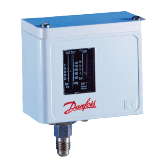
Installation Guide
Single Pressure Control
Type KPU
Application
KPU pressure controls are for use on commercial
refrigeration and air conditioning systems to give protection
against excessively low suction pressure or excessively
high discharge pressure.
They are also used for starting and stopping refrigeration
compressors and fans on air-cooled condensers.
KPU pressure controls are fitted with the Single-Pole Single-
Throw (SPST) or Single-Pole Double-Throw (SPDT) switches,
suitable for direct as well as indirect (with a contactor) control.
Product Specification
Application
Type
¼ in.
male flare
060-5231
KPU 1
060-5236
KPU 1
Low Pressure
Control
060-5237
KPU 2
Cut Out on
pressure fall
KPU 2
060-5239
KPU1B
060-5232
Fan control
KPU 5
060-5241
High Pressure
KPU 6W
060-5243
Control
Cut Out on
KPU 6B
060-5244
pressure rise
* 610psig - MWP for products used according to 97/23/EG PED directive.
Installation
Select an accessible location, where the control and pressure
connection line will not be subject to damage.
© Danfoss A/S (AC-MCI / jmn), 2012-12
Code number
36 in. cap.
Reset
tube w. ¼ in.
flare nut
060-5233
Auto.
—
Auto.
060-5235
Auto.
060-5240
Auto.
060-5234
Man (Min.)
060-5242
Auto.
060-5245
Auto.
060-5246
Man. (Max.)
DKRCC.PI.CD0.F1.22 / 520H6076
KPU pressure controls are available in several pressure ranges
and are compatible with HCFC and non-flammable HFC
refrigerants. KPU 6W and KPU 6B are fail safe controls for high
pressure refrigerants (R410A and R744). Standard enclosure is
~NEMA 1
Contact system
Regulating
range
Switch
[inHg]
Type
action
[psig]
—
SPDT
6 in. – 108
SPST(NO) close High open Low
6 in. – 108
SPST(NO) close High open Low
6 in. – 73
SPDT
—
6 in. – 73
SPDT
—
28 in. – 100
SPST(NO) close High open Low
100 – 465
SPDT
—
100 – 600
SPDT
—
100 – 600
IMPORTANT:
Mount the pressure control in a position that will
allow drainage of liquids away from control bellows.
Pressure connection of the control must always be
located on the top side of the refrigerant line.
This reduces the possibility of oil, liquids, or
sediment collecting in the bellows, which could
cause the control malfunction.
IMPORTANT:
Ensure the ambient temperature for the pressure
control is higher than the refrigeration line as that
will prevent liquid migration and accumulation in
the bellows.
Max.
Max.
Differential
working
testing
∆p
pressure
pressure
[psi]
[psig]
[psig]
10 – 60
250
290
10 – 60
250
290
6 – 30
250
290
6 – 30
250
290
10 fixed
250
290
25 – 85
510
530
58 – 145
675 / 610*
725
60 fixed
675 / 610*
725
Ambient
temp.
[°F]
-40 – 122
(175 for max.
2 hours)
1
Advertisement

Related Manuals for Danfoss KPU 1


Summary of Contents for Danfoss KPU 1
- Page 1 IMPORTANT: Ensure the ambient temperature for the pressure control is higher than the refrigeration line as that will prevent liquid migration and accumulation in the bellows. © Danfoss A/S (AC-MCI / jmn), 2012-12 DKRCC.PI.CD0.F1.22 / 520H6076...
- Page 2 16 A 16 A 10 A 112 A 12 W The terminal block as well as grounding screw 400 V 220 V are accessible after dismounting of the front cover. DKRCC.PI.CD0.F1.22 / 520H6076 © Danfoss A/S (AC-MCI / jmn), 2012-12...
- Page 3 Do not adjust pointers beyond the highest or lowest controls with manual reset it is necessary indicator marks on the scale plate, as this may cause to push the reset knob. inaccurate control operation. © Danfoss A/S (AC-MCI / jmn), 2012-12 DKRCC.PI.CD0.F1.22 / 520H6076...
- Page 4 The Differential pressure value is fixed 2. The Cut In setting equals the Cut Out and printed on the scale plate. less the Differential: CUT IN = CUT OUT - 60 psi DKRCC.PI.CD0.F1.22 / 520H6076 © Danfoss A/S (AC-MCI / jmn), 2012-12...