Advertisement
Quick Links
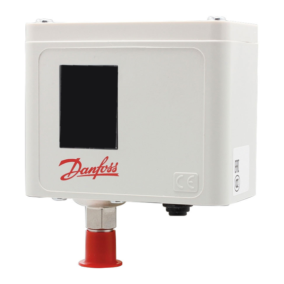
Types
The controls can be used with CFC, HFC
and HCFC refrigerants.
CAUTION: Do not install these controls on
ammonia systems.
Mounting requirements
CAUTION: Do not mount the control in a position where dirt,
sediment, or oil will affect the operation of the control.
Test pressure (p
)
TEST
Enclosure
CAUTION: The mounting panel must be plane to avoid damage of control.
© Danfoss A/S
INSTRUCTIONS
KP 5, KP 7W, KP 7B
Auto reset: KP 1, KP 2, KP 5, KP 7W
p
max.:
test
KP 1, 2: 285 psig (20 bar p
KP 5, 7: 505 psig (35 bar p
KP 1, KP 2,
Manual reset: KP 1, KP 5, KP 7B
Ambient temperatures
t
min.
KP 1, 2, 5: –40°F (–40°C)
1
KP 7:
t
max.
1
Connections
)
e
)
e
RI.05.1A.22
–13°F (–25°C)
150°F (65°C)
RI.5A.J1.22 01-1999
Advertisement

Related Manuals for Danfoss KP 1


Summary of Contents for Danfoss KP 1
- Page 1 The controls can be used with CFC, HFC and HCFC refrigerants. CAUTION: Do not install these controls on ammonia systems. Auto reset: KP 1, KP 2, KP 5, KP 7W Manual reset: KP 1, KP 5, KP 7B Mounting requirements Ambient temperatures min.
- Page 2 To resume control operation after safety cutout, push reset knob as indicated. Note: Note: KP 1, KP 5 and KP 7B w/man. reset: KP 1, man. reset is possible only after a Push manual reset knob during manual pressure rise of 10 psi (0.7 bar).
- Page 3 Setting (se also “Wiring”) KP 1 (auto reset), KP 2, KP 5, KP 7W and KP 7B KP 1 (manual reset ONLY) 1. Adjust range spindle to desired 1. Adjust range spindle to desired HIGH SET POINT (HSP) LOW SET POINT (LSP) 2.
- Page 4 RI.5A.J1.22 © Danfoss A/S (AC-SP,jp) 01-1999...