Advertisement
Quick Links
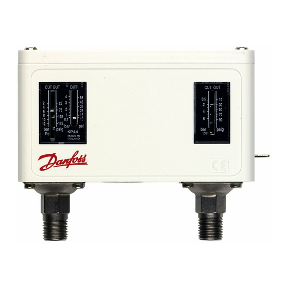
Installation guide
Dual pressure switch
Type KP 44
Ambient temperatures
t
min.
1
t
max.
1
Caution: Do not mount the control in a position
where dirt, sediment or oil will affect the operatio
of the control.
Connections
Enclosure
Caution: The mounting panel must be plane
to avoid damage of control.
© Danfoss A/S (AC-MCI /jmn), 2014-01
-40 °C (-40 °F)
65 °C (150 °F)
DKRCC.PI.CD0.B2.02 / 520H8364
Test pressure (p
)
test
Control
Control PS/MWP
Safety PS/MWP
1. Lefthand pressure setting spindle
2. Differential setting spindle
3. Main arm
4. Righthand pressure setting spindle
5. Main spring
6. Differential spring
7. Bellows
8. Pressure connections
9. Contact system
10. Terminal
11. Earth terminal
12. Cable entry
13. Tumbler
14. Locking plate
15. Impulse lever
The switch in the KP has a snap-action function and the
bellows moves only when the cut-in or cut-out value is
reached.
Mounting
Safety
P
max.
test
19 bar P
(275 psig)
e
P
max.
test
(362 psig)
25 bar P
e
17 bar P
(245 psig)
e
17 bar P
(245 psig)
e
1
Advertisement

Related Manuals for Danfoss KP 44


Summary of Contents for Danfoss KP 44
-
Page 1: Installation Guide
The switch in the KP has a snap-action function and the bellows moves only when the cut-in or cut-out value is reached. Enclosure Mounting Caution: The mounting panel must be plane to avoid damage of control. © Danfoss A/S (AC-MCI /jmn), 2014-01 DKRCC.PI.CD0.B2.02 / 520H8364... - Page 2 4 bar (58 psi) + 1 bar (15 psi) = 5 bar (73 psi) Adjustment Control side setting Control side differential Safety side setting Note: Remove lockplate before adjustment Replace lockplate after adjustment (if desired). DKRCC.PI.CD0.B2.02 / 520H8364 © Danfoss A/S (AC-MCI /jmn), 2014-01...