Table of Contents
Advertisement
Quick Links
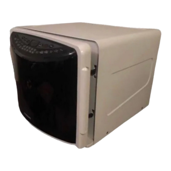
MICROWAVE OVEN
MD1200WD
SERVICE
Manual
MICROWAVE OVEN
CONTENTS
1. Precaution .......................................... 1
2. Specifi cations .................................... 3
3. Operating Instructions....................... 4
4. Disassembly and Reassembly............5
5. Alignment and Adjustment..................9
6. Troubleshooting ............................... 13
7. Exploded Views and Parts List ........15
8. PCB Diagrams .................................. 19
9. Schematic Diagrams ........................ 21
SEA
Advertisement
Table of Contents

Related Manuals for Samsung MD1200WD


Summary of Contents for Samsung MD1200WD
-
Page 1: Table Of Contents
MICROWAVE OVEN MD1200WD SERVICE Manual MICROWAVE OVEN CONTENTS 1. Precaution .......... 1 2. Specifi cations ........3 3. Operating Instructions....... 4 4. Disassembly and Reassembly....5 5. Alignment and Adjustment....9 6. Troubleshooting ....... 13 7. Exploded Views and Parts List ..15 8. - Page 2 © Samsung Electronics Co., Ltd. May 2004 This Service Manual is a property of Samsung Electronics Co.,Ltd. Printed in Korea Any unauthorized use of Manual can be punished under applicable Code No. : DE68-03544A International and/or domestic law.
- Page 3 PRECAUTIONS TO BE OBSERVED BEFORE AND DURING SERVICING TO AVOID POSSIBLE EXPOSURE TO EXCESSIVE MICROWAVE ENERGY (a) Do not operate or allow the oven to be (c) Before turning on microwave power for operated with the door open. any service test or inspection within the (b) Make the following safety checks on all microwave generating compartments, ovens to be serviced before activating the...
-
Page 4: Precaution
1. Precaution Follow these special safety precautions. Although the microwave oven is completely safe during ordinary use, repair work can be extremely hazardous due to possible exposure to microwave radiation, as well as potentially lethal high voltages and currents. 1-1 Safety precautions ( 1. - Page 5 1-2 Special Servicing Precautions (Continued) 17. When checking the continuity of the witches or transformer, always make sure that the power is OFF, and one of the lead wires is disconnected. 18. Components that are critical for safety are indi- cated in the circuit diagram by shading, 19.
-
Page 6: Specifi Cations
2. Specifi cations 2-1 Table of Specifi cations TIMER 99 MINUTES 99SECONDS POWER SOURCE 120V 60Hz, AC POWER CONSUMPTION MICROWAVE : 1,500W OUTPUT POWER FROM 100 TO 1000W ( 10 LEVEL POWER ) (ICE-705 TEST PROCEDURE) 2,450MHz OPERATING FREQUENCY MAGNETRON OM75S(20) COOLING METHOD COOLING FAN MOTOR... -
Page 7: Operating Instructions
3. Operating Instructions 3-1 Control Panel 1. One Minute+ 8. Sound Button Press once for every minute of cooking at High Power. Sets sound on or off. 2. Auto Defrost 9. Pause/Cancel Sets weight of food to be defrosted. Press to pause oven or correct a mistake. 3. -
Page 8: Disassembly And Reassembly
4. Disassembly and Reassembly 4-1 Replacement of Magnetron, Motor Assembly and Lamp Remove the magnetron including the shield case, permanent magnet, choke coils and capacitors (all of which are contained in one assembly). 1. Disconnect all lead wires from the magnetron. 2. - Page 9 4-3 Replacement of Door Assembly 4-3-1 Removal of Door Assembly 1. Remove the door-c. 2. Remove the door-e DOOR "C" 4-3-2 Removal of Sub P.C.B Assembly 1. Disconnect all lead wires from the Sub P.C.B 2.Disassembly Sub P.C.B DOOR “E” 4-3-3 Removal of Membrane Panel 1.
- Page 10 4-4 Replacement of Fuse 1. Disconnect the oven from the power source. 2. When 15A fuse blows out by the operation of interlock monitor switch failure, replace the primary interlock switch, door sensing switch, monitor switch and power relay. 3. When the above three switches operate properly, check if any other part such as the control circuit board, blower motor or high voltage transformer is defective.
- Page 11 4-6-2 Removal of Door “E” 1. Following the procedure as shown in the fi gure, insert and bend a thin metal plate between Door “E” and Door “A” until you hear the ‘tick’ sound. 2. Insertion depth of the thin metal plate should be 0.5mm or less.
-
Page 12: Alignment And Adjustment
5. Alignment and Adjustments PRECAUTION 1. High voltage is present at the high voltage terminals during any cook cycle. 2. It is neither necessary nor advisable to attempt measurement of the high voltage. 3. Before touching any oven components or wiring, always unplug the oven from its power source and dis- charge the high voltage capacitor. - Page 13 5-4 High Voltage Capacitor 1. Check continuity of the capacitor with the meter set at the highest resistance scale. 2. Once the capacitor is charged, a normal capacitor shows continuity for a short time, and then indicates 9MΩ. 3. A shorted capacitor will show continuous continuity. 4.
- Page 14 5-8 Output Power of Magnetron CAUTION MICROWAVE RADIATION PERSONNEL SHOULD NOT ALLOW EXPOSURE TO MICROWAVE RADIATION FROM MICROWAVE GENERA- TOR OR OTHER PARTS CONDUCTING MICROWAVE ENERGY. The output power of the magnetron can be measured by performing a water temperature rise test. Equipment needed : * Two 1-liter cylindrical borosilicate glass vessel (Outside diameter 190 mm) * One glass thermometer with mercury column...
- Page 15 5-10 Procedure for Measurement of Microwave Energy Leakage 1) Pour 275±15cc of 20±5°C(68±9°F) water in a beaker which is graduated to 600cc, and place the beaker in the center of the oven. 2) Start to operate the oven and measure the leakage by using a microwave energy survey meter.
-
Page 16: Troubleshooting
6. Troubleshooting PRECAUTION 1. CHECK GROUNDING BEFORE CHECKING FOR TROUBLE. 2. BE CAREFUL OF THE HIGH VOLTAGE CIRCUIT. 3. DISCHARGE THE HIGH VOLTAGE CAPACITOR. 4. WHEN CHECKING THE CONTINUITY OF THE SWITCHES OR TRANSFORMER, DISCONNECT ONE LEAD WIRE FROM THESE PARTS AND THEN CHECK CONTINUITY WITHOUT THE POWER SOURCE ON. TO DO OTHERWISE MAY RESULT IN A FALSE READING OR DAMAGE TO YOUR METER. - Page 17 6-1 Electrical Malfunction(continued) SYMPTOM CAUSE CORRECTIONS Oven lamp and fan motor 1. Misadjustment or loose wiring Adjust door and latch switches. turn on of secondary latch switch 2. Defective Secondary latch switch Oven can program but 1. Open or loose wiring of secondary Adjust door and interlock switches.
-
Page 18: Exploded Views And Parts List
7. Exploded Views and Parts List 7-1 Exploded Views M001 M030 M036 M029 M039 M040 H018 M041 M020 T017 B018 B006 M035 B001 M049 B002 B010 M015 T001 B011 B001 M048 W002 M038 M047 - 15 -... - Page 19 LATCH-BODY MD1200WD,PP(FH44N),-,-,-,-,1. B010 DE66-00093A LEVER SWITCH (A) NC2000 PP-TH53 NTR HA B011 DE66-00094A LEVER-SWITCH(B) NC2000,PP-TH53,-,-,-,-,N BODY-LATCH B018 DE96-00375A ASSY BODY LATCH MD1200WD,1.2 ROUND H018 DE31-90057A BLADE-FAN PP,T1.5,-,3RD-W,-,-,- M001 DE64-01166A PANEL-OUTER MD12000WD/XAA,CAOTING,T0.5,- M015 DE39-20146E ASSY POWER CORD MSP-36,-,-,-,-,-,SPT-2 3 M020 DE96-00384A...
- Page 20 ASSY DOOR-E(COATING) MD1200WD,COATING,1. D006 DE64-01170A DOOR-C MD1200WD,PP(TB53),-,-,-,-,BLK,1.2 D007 DE61-00193A SPRING-KEY M1733,HSWR,D5.5,19 1/4 T0.6 DOOR-E*KEY-DOOR D011 DE64-00891A KEY-DOOR MW8ROWC,POM(F20-02),T2.0,-,BLK, DOOR-E D049 DE31-10162A ASSY DOOR MD1200WD,PURE-WHITE,1.2 ROUND D078 DE96-00401A ASSY-DISPLAY KIT MD1200WD,DISPLAY KIT SCREEN-DOOR S.N.A : SERVICE NOT AVAILABLE - 17 -...
- Page 21 7-4 Standard Parts List Code No. Description Specifi cation Q’ty Remark DE60-30015A NUT-FLANGE M5,P0.8,MSWR10,FEFZY,-,-,-,-,- DE60-10082I SCREW-A -,-,-,-,2S-4X12,FEFZY,-,-,-,- BASE-PLATE DE60-10082I SCREW-A -,-,-,-,2S-4X12,FEFZY,-,-,-,- CAVER-MOTOR DE60-10082I SCREW-A -,-,-,-,2S-4X12,FEFZY,-,-,-,- DECORATION DE60-10082I SCREW-A -,-,-,-,2S-4X12,FEFZY,-,-,-,- PCB+COVER-MOTOR DE60-10051A SCREW-TAP PH -,-,MSWR,-,PH,M4,-,L6,-,- DRIVE MOTOR 6002-000239 SCREW-TAPPING TH,+,2S,M4,L8,ZPC(YEL),SM20C BKT-MGT 6002-001170 SCREW-TAPPING FH,STAR,2,M4,L12,SIL,SWRCH18A...
-
Page 22: Pcb Diagrams
8. P.C.B Diagrams 8-1 P.C.B Diagrams ( This Document can not be used without Samsung’s authorization ) CN04 SMW250-04V_RED CN02 SMW250-04V_WHT SMW250-05V_WHT CN05 DSP1 CSE-4048 - 19 -... - Page 23 8-2 P.C.B Parts List Code No. Description Specifi cation Q’ty Remark DE30-20016A BUZZER CBE2220BA,STICK,-,-,-,-,-,-,- BZ01 2401-000151 C-AL 1000uF,20%,25V,GP,TP,10x20,5 2401-000911 C-AL 22uF,20%,16V,GP,TP,5x7,5 2401-002075 C-AL 4.7uF,20%,50V,GP,TP,5x11,5 2401-003107 C-AL 47uF,20%,16V,GP,TP,5x7,5 2203-000192 C-CER,CHIP 100nF,+80-20%,50V,Y5V,TP,2012, C04~C07,C20 2203-000444 C-CER,CHIP 1nF,10%,50V,X7R,TP,2012,- C15~C19 2202-000252 C-CERAMIC,MLC-AXIAL 4.7nF,10%,50V,X7R,TP,2.5x4.3,- 3711-000940 CONNECTOR-HEADER BOX,4P,1R,2.5mm,STRAIGHT,SN CN02 3711-002001...
-
Page 24: Schematic Diagrams
9. Schematic Diagrams 9-1 Schematic Diagrams ( This Document can not be used without Samsung’s authorization ) MAGNETRON BLK BLU HIGH VOLTAGE DIODE TO CHASSIS SECONDARY SWITCH HIGH VOLTAGE CAPACITOR RED BLU DOOR SENSING SWITCH MONITOR SWITCH BOTTOM CENTER SYMBOL...