Table of Contents
Advertisement
Please carefully read this manual, and save this manual for future use.
Before using this product, be sure to read "Read this first!" (pages 2 to 6).
PJ PSJ EJ ESJ
W1020SQ1041 -FJ
Operating Instructions
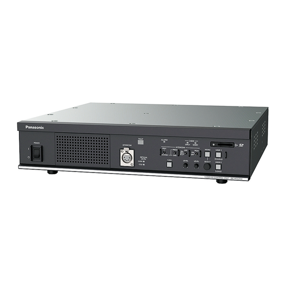
AK-HCU250P
Model No.
AK-HCU250PS
Model No.
AK-HCU250E
Model No.
AK-HCU250ES
Model No.
Camera Control Unit
ENGLISH
DVQP2430YA
Advertisement
Table of Contents

Related Manuals for Panasonic AK-HCU250P


Summary of Contents for Panasonic AK-HCU250P
- Page 1 Operating Instructions Camera Control Unit AK-HCU250P Model No. AK-HCU250PS Model No. AK-HCU250E Model No. AK-HCU250ES Model No. Please carefully read this manual, and save this manual for future use. Before using this product, be sure to read “Read this first!” (pages 2 to 6).
-
Page 2: Read This First
Operation at a voltage other than 120 V AC may require interference, use the recommended accessories only. the use of a different AC plug. Please contact either a local or foreign Panasonic authorized service center for CAUTION: assistance in selecting an alternate AC plug. - Page 3 FCC NOTICE (USA) Supplier’s Declaration of Conformity Model Number: AK-HCU250P/AK-HCU250PS Trade Name: Panasonic Responsible Party: Panasonic Corporation of North America Two Riverfront Plaza, Newark, NJ 07102 Support contact: 1-800-524-1448 This device complies with part 15 of the FCC Rules. Operation is subject to the following two conditions: (1) This device may not cause harmful interference, and (2) this device must accept any interference received, including interference that may cause undesired operation.
- Page 4 Fuse If you lose the fuse cover the plug must not be used until a replacement cover is obtained. Fuse A replacement fuse cover can be purchased from your local Panasonic Dealer. indicates safety information. - 4 -...
- Page 5 Read this first! EMC NOTICE FOR THE PURCHASER/USER OF THE APPARATUS 1. Pre-requisite conditions to achieving compliance with the above standards <1> Peripheral equipment to be connected to the apparatus and special connecting cables • The purchaser/user is urged to use only equipment which has been recommended by us as peripheral equipment to be connected to the apparatus.
- Page 6 Read this first! Manufactured by: Panasonic Corporation, Osaka, Japan Importer’s name and address of pursuant to EU rules: Panasonic Marketing Europe GmbH Panasonic Testing Centre Winsbergring 15, 22525 Hamburg, Germany Disposal of Old Equipment Only for European Union and countries with recycling systems This symbol on the products, packaging, and/or accompanying documents means that used electrical and electronic products must not be mixed with general household waste.
-
Page 7: Table Of Contents
Table of Contents Read this first! ............. 2 AUDIO ................46 MIC OUT ..............46 Introduction ..............8 CCU INTERCOM TALK ..........46 How to View This Manual ..........8 INTERCOM ..............47 About trademarks and registered trademarks .....8 PGM ................47 About copyright ............8 MAINTENANCE.............48 Illustrations and screen displays featured in the START UP ..............48 manual .................8... -
Page 8: Introduction
Model number of unit Model number given in manual AK-HC3900G AK-HC3900 AK-HC3900GS AK-HRP1000G AK-HRP1000 AK-HRP1005G AK-HRP1005 AK-HCU250P AK-HCU250PS AK-HCU250 AK-HCU250E AK-HCU250ES AK-MSU1000G AK-MSU1000 Overview This camera control unit (CCU) is designed to be used with the HD studio camera (AK-HC3900; sold separately). -
Page 9: Notice
Notice Disclaimer of warranty IN NO EVENT SHALL Panasonic Corporation BE LIABLE TO ANY PARTY OR ANY PERSON, EXCEPT FOR REPLACEMENT OR REASONABLE MAINTENANCE OF THE PRODUCT, FOR THE CASES, INCLUDING BUT NOT LIMITED TO BELOW: ● ANY DAMAGE AND LOSS, INCLUDING WITHOUT LIMITATION, DIRECT OR INDIRECT, SPECIAL, CONSEQUENTIAL OR EXEMPLARY, ARISING OUT OF OR RELATING TO THE PRODUCT;... -
Page 10: Accessories
Power cable Rack mount adapters* ……………2 ● for AK-HCU250P / AK-HCU250PS……………1 “Mounting the rack mount adapters” (see page 13) ● for AK-HCU250E / AK-HCU250ES……………2 *1: The screws for the rack mount adapters come attached to the unit. - 10 -... -
Page 11: Precautions For Use
Insert the SD card to which the file has been written into a computer and select "LICENSE.TXT". For details on these descriptions (originally provided in English) and how to obtain the source code, visit the following website. https://pro-av.panasonic.net/ We do not accept inquiries about the details of the source code obtained by the customer. -
Page 12: Precautions For Installation
Introduction Precautions for Installation In addition to the safety precautions given in “Read this first!”, also observe the following instructions. Be sure to ask your dealer to perform the installation and connection work for the unit. Connecting a power supply ●... -
Page 13: Mounting The Unit In A Rack
Introduction Mounting the unit in a rack Mounting the rack mount adapters 1. Remove the setting legs (A) secured to the unit. Remove them using a Phillips screwdriver. 2. Mount the supplied rack mount adapters (B). ● Mounting screws are not supplied. Use mounting screws removed from the unit using a Phillips screwdriver. Tighten the mounting screws for rack mount adapters using a torque of 110 N·m or more. -
Page 14: Connection
Connection Connection System configuration Serial connection Use the optical fiber multi cable (sold separately) to connect the unit and camera. Use a ROP cable to connect the unit to the ROP (AK-HRP250 / AK-HRP1000 / AK-HRP1005). For the connection procedure, see "Equipment connections." “Equipment connections”... -
Page 15: Setting The User Account
Use the following procedure to register the account on this unit. Software To install the software, download User Account Setup Software (AccoutGen) from the following website. (Windows) https://pro-av.panasonic.net/ r User Account Setup Software (AccoutGen) User account setting of this unit can be set using User Account Setup Software. -
Page 16: Equipment Connections
Connection Equipment connections ● Before proceeding with the connections, check that the power of the unit and camera is OFF. ● Use the optical fiber multi cable to connect the unit and camera. Connect only the AK-HC3900 camera: Do not connect any other model. ●... -
Page 17: Parts And Their Functions
Parts and their functions Parts and their functions Front panel 1 [POWER] switch This is the unit’s power switch. Move it to the ON position to turn on the power. ON ( ) OFF ( [TALLY] lamps The lamp remains lit while tally signals (R) are input. [OPTICAL LEVEL] indicators Indicates the reception status of optical transmission. -
Page 18: Front Panel 2
Parts and their functions Front panel 2 [ALARM] indicator ● [ALARM] indicator Lights when the unit malfunctions. [CABLE] indicators Lights to indicate the cable connection status. ● [OPEN] indicator This lights when the unit and camera are not connected by the optical fiber multi cable. ●... -
Page 19: Front Panel 3
Parts and their functions Front panel 3 [MENU] button When you hold down the [MENU] button, the menu screen is displayed on the picture monitor and the [MENU] button lights. If you hold down the [MENU] button while the menu is displayed, the menu closes and the [MENU] button turns off. -
Page 20: Rear Panel 1
Parts and their functions Rear panel 1 [HD SDI OUT] connectors [1] to These connectors (BNC) are for outputting 3G/1.5G-SDI signals. Signals output can be selected from the CCU menu. ● Connect with a 5C-FB cable or better. [HD SDI OUT] connector These connectors (BNC) are for outputting 1.5G-SDI signals. -
Page 21: Rear Panel 2
Parts and their functions Rear panel 2 [LAN] connector It is the LAN connector (RJ45) for connecting the ROP (AK-HRP250 / AK-HRP1000 / AK- HRP1005) with an IP connection. Use a switch hub and connect the devices with a 10BASE-T/100BASE-TX straight cable. This connector is for connecting a personal computer when configuring Web settings. -
Page 22: Picture Monitor (Pm)
Picture monitor (PM) Picture monitor (PM) Picture monitor displays Display the camera statuses, warnings, and other information on the picture monitor using the operation panel of the ROP. Press the [CHARA] button (A) of the ROP to display the desired information. ●... -
Page 23: Transition Of Displays
Picture monitor (PM) Transition of displays When trouble is detected, warning information is automatically displayed on the picture monitor. Even if status information or operation information is already displayed on the picture monitor when trouble is detected, priority is given to the display of the warning information. -
Page 24: Information Display
Picture monitor (PM) Information display This information is displayed on the picture monitor (PM). Warning displays The warning information is displayed when trouble is detected in the unit, camera, or optical fiber multi cable. - WARNING - CAM RCV LV L N G CCU RCV LV L N G ●... -
Page 25: Iris Display
Picture monitor (PM) IRIS display When the information is not displayed on the picture monitor, display it by pressing the [CHARA] button of the ROP. M EM: F5.6 F4 .8 -- ----- --+---- --- --- A. Camera number B. -
Page 26: Status Displays
Picture monitor (PM) Status displays From the IRIS display screen, press the [CHARA] button of the ROP to display the “status display screen”. However, when the “IRIS LEVEL” setting is “OFF”, the screen will be displayed first if the [CHARA] button of the ROP is pressed when the information is not displayed on the picture monitor. - Page 27 Picture monitor (PM) Status displays (page 1 of 7) -Status1- HLG MODE SDR MODE HLG B.GAMMA HLG KNEE SDR CONV GAIN SDR CONV POINT SDR CONV SLOPE Item Display range Remarks HLG MODE The HLG mode is displayed here. SDR MODE The SDR mode is displayed here.
- Page 28 Picture monitor (PM) Status displays (page 2 of 7) -Status2- CAM No. BLACK SHADING WHITE SHADING FLARE GAMMA BLACK GAMMA KNEE WHITE CLIP DRS SW MATRIX SHUTTER Item Display range Remarks CAM No. 1 to 99 The camera number is displayed here. BLACK SHADING The status of the black shading is displayed here.
- Page 29 Picture monitor (PM) Status displays (page 3 of 7) -Status3- GAMMA MODE FLIKE1 M.GAIN 36dB M.GAIN VAR -2.9dB DETAIL SKIN TONE DETAIL DC DETAIL DC SKIN TONE DETAIL ND FILTER **** LENS EXTENDER AUTO IRIS SCENE FILE SCENE0 Item Display range Remarks GAMMA MODE The selected gamma type is displayed here.
- Page 30 Picture monitor (PM) Status displays (page 4 of 7) -Status4- RETURN1 RET1 RETURN2 RET2 Item Display range Remarks RETURN1 RET1 The input assignment for return signals is displayed here. RET2 RETURN2 - 30 -...
- Page 31 Picture monitor (PM) Status displays (page 5-1 of 7) 5-1/7 -Status5- HD SDI OUTPUT1 HD SDI OUTPUT2 1080p-HDR HD SDI OUTPUT3 1080p-HDR HD SDI OUTPUT4 1080i Item Display range Remarks HD SDI OUTPUT1 1080p/1080i/1080-29.97PsF/ The output formats for connectors HD SDI OUTPUT1, HD SDI 1080-23.98PsF/1080-23.98p over 59.94i/ OUTPUT2, and HD SDI OUTPUT3 are displayed here.
- Page 32 Picture monitor (PM) Status displays (page 6 of 7) -Status6- HD TRUNK HD TRUNK Item Display range Remarks HD TRUNK HD TRUNK The signal to be output from the [HD TRUNK OUT] connector is displayed here. Status displays (page 7 of 7) -Status7- BUTTON ASSIGN USER1...
-
Page 33: Operation Displays
Picture monitor (PM) Operation displays The operation displays appear at the bottom of the screen for approx. 4 seconds when any of the following operations have been performed with the operation panel of the ROP. ● Master gain change ● Electronic shutter change ●... -
Page 34: Auto Displays
Picture monitor (PM) Auto displays When the following operation is performed while no menu is displayed on the picture monitor, information on the operation performed appears at the bottom of the screen. ● AWB (Auto White Balance) function ● ABB (Auto Black Balance) function The display is cleared 4 seconds after the operations are completed. -
Page 35: Ccu Menu
CCU menu CCU menu Menu operations While viewing the menu screen of the picture monitor, operate the [MENU] button and [SELECT] dial on the front panel. A. [MENU] button B. [SELECT] dial Displaying and hiding the menus Menus are displayed or hidden by the following procedure. 1. -
Page 36: Basic Menu Operations
CCU menu Basic menu operations Menu items are selected and set by the following procedure. 1. Turn the [SELECT] dial while in the [CCU MENU], select [OPERATION] or [MAINTENANCE], and then press the [SELECT] dial. A list of menu items included in the selected item ([OPERATION] or [MAINTENANCE]) is displayed. •... - Page 37 CCU menu 3. Turn the [SELECT] dial to move the cursor to the menu item you want to set, and then press the [SELECT] dial. The setting value of the selected menu item starts flashing and you can change it. SETTING RETURN FS BAR SELECT...
-
Page 38: Operation With Menu Items That Have Multiple Setting Items On One Line
CCU menu Operation with menu items that have multiple setting items on one line 1. Turn the [SELECT] dial to move the cursor to the menu item you want to set, and then press the [SELECT] dial. The cursor becomes “↓” and you can use the [SELECT] dial to move the cursor to a setting item in the selected menu item. BA R ID BA R ID S WI TC H BR IG HT NE SS... -
Page 39: Text Input
CCU menu Text input 1. Turn the [SELECT] dial to move the cursor to the menu item where text is to be input, and then press the [SELECT] dial. The cursor display changes as indicated by "↓". By turning the [SELECT] dial, you can move the cursor to the next (previous) character position. - Page 40 CCU menu NOTE ● Turning the [SELECT] dial clockwise while pressing it increases the speed at which the number increases (turning it counterclockwise decreases the number). Turning the dial more increases the speed even more. This operation is effective for making a large change to a value when the setting width is large (e.g., IP address or port number).
-
Page 41: Menu Composition
CCU menu Menu composition This is the first screen displayed when you press the [MENU] button. Select one of the menus. CCU MENU OPERATION AUDIO MAINTENANCE Item Content Details page OPERATION Makes settings for items such as the system format “OPERATION”... -
Page 42: Operation
Enables/disables the HDR mode. HD SDI Enables/disables the HDR mode for HD SDI OUTPUT3. OUTPUT3(HDR) HD SDI Enables/disables the HDR mode for HD SDI OUTPUT1&2. OUTPUT1&2(HDR) ● Enabled only when the 4K OPTION board is fitted. *1: AK-HCU250P/250PS *2: AK-HCU250E/250ES - 42 -... -
Page 43: In/Out Select
CCU menu IN/OUT SELECT This is the selection screen for the IN/OUT SELECT menu. ___ indicates factory default settings. Item Setting value Setting details SDI OUTPUT1&2 Sets the format of the signal output from SDI1&2. 1.5G ● Fixed to 1.5G when SYSTEM 720p. SDI OUTPUT3 Sets the format of the signal output from SDI3. -
Page 44: Setting
CCU menu SETTING This is the selection screen for the SETTING menu. ___ indicates factory default settings. Item Setting value Setting details RETURN FS Set the delay mode for the HD return signals. BAR SELECT Sets the color bar signal. SMPTE ARIB EIAJ... -
Page 45: Bar Id
CCU menu BAR ID This is the selection screen for the BAR ID menu. ___ indicates factory default settings. Item Setting value Setting details BAR ID SWITCH Shows/hides the ID superimposed on the color bars. BRIGHTNESS 0 to 100% Sets the luminance for the ID display. ID1 POSITION V 0 to 05 Sets the vertical position for the start of the ID1 display. -
Page 46: Audio
CCU menu AUDIO This is the selection screen for the AUDIO menu. Item Content Details page MIC OUT Makes settings for microphone output. “MIC OUT” (see page 46) CCU INTERCOM TALK Makes settings for the microphone of the intercom. “CCU INTERCOM TALK” (see page 46) INTERCOM Makes settings for the intercom. -
Page 47: Intercom
CCU menu INTERCOM This is the selection screen for the INTERCOM menu. ___ indicates factory default settings. Item Setting value Setting details 4W/RTS Select the intercom voice I/O method. 4W INPUT LEVEL -40dB to 0dB to +20dB Switch the 4W (intercom) input level. (1dB Step) 4W OUTPUT LEVEL -40dB to 0dB to +20dB... -
Page 48: Maintenance
CCU menu MAINTENANCE This is the selection screen for the MAINTENANCE menu. Item Content Details page START UP Sets the behavior when the unit's power is turned “START UP” (see page 48) SETUP Sets the SW&BUTTON and various connection “SETUP” (see page 49) related settings. -
Page 49: Setup
CCU menu SETUP This is the selection screen for the SETUP menu. ___ indicates factory default settings. Item Setting value Setting details IRIS SCALE FULL Set the IRIS display range of the status display screen. 2STOP CABLE HYBRID Sets the cable used to connect the camera. CONNECTION FIBER HYBRID... -
Page 50: Nd Name
CCU menu ND NAME This is the selection screen for the ND NAME menu. Item Setting value Setting details ND FILTER1 NAME 5 characters Sets the name of the ND filter 1 (maximum of 5 characters). ND FILTER2 NAME 5 characters Sets the name of the ND filter 2 (maximum of 5 characters). -
Page 51: Pm View Setting(1/2)
CCU menu PM VIEW SETTING(1/2) This is the selection screen for the PM VIEW SETTING(1/2) menu. ___ indicates factory default settings. Setting Item Setting details value CAMERA NO Shows/hides the camera number. SYSTEM MODE Shows/hides the system mode. SCENE FILE No Shows/hides the scene file number. -
Page 52: Pm Operation Status
CCU menu PM OPERATION STATUS This is the selection screen for the PM OPERATION STATUS menu. ___ indicates factory default settings. Setting Item Setting details value STATUS DISPLAY TIME Sets the time for displaying the status. MANUAL OPERATION STATUS Shows/hides when MASTER GAIN is operated. MASTER GAIN Shows/hides when SHUTTER is operated. -
Page 53: Sd Card
CCU menu SD CARD This is the selection screen for the SD CARD menu. ___ indicates factory default settings. Setting Item Setting details value DATA SAVE Save settings data to a memory card. DATA LOAD Load the settings data that has been saved to a memory card. CARD FORMAT Initialize the memory card. -
Page 54: Troubleshooting
Troubleshooting Troubleshooting Operation Symptom Cause and Measure Cannot turn the power on. ● Is the power cable connected to the outlet properly? Cannot perform operation from ● Is the power on? an ROP connected with an IP • If the [POWER] lamp of this unit is off, the power of this unit is not turned on. connection. -
Page 55: Reference
Reference Reference Connector pin assignment table [INTERCOM] connector (page 18: 10) HA16PRH-5S (Hirose Electric Co., Ltd.) Pin No. Function Remarks SHIELD Carbon MIC: -1 dB TALK Dynamic MIC: -5 dB SHIELD ● Select from [DYN], [ECM], and [CBN] in the [AUDIO] menu, [CCU INTERCOM TALK] → RECEIVE [MIC TYPE] [COMMUNICATION] connector (page 21: 2) - Page 56 Reference Example of tally input connections AK-HCU250 R TALLY IN (H) G TALLY IN (H) 2.2 k R TALLY IN (C) G TALLY IN (C) 12.4 k AK-HCU250 R TALLY IN (H) G TALLY IN (H) 3.9 k R TALLY IN (C) G TALLY IN (C) 12.4 k *1: Equivalent circuit...
- Page 57 Reference [MIC1] and [MIC2] connectors (page 21: 4) HA16RV-3PG(76) (Hirose Electric Co., Ltd.) Pin No. Function Flow of signal Remarks SHIELD 0 dBm, 600 Ω CCU→SYSTEM COLD CCU→SYSTEM ● When connecting to an unbalanced input terminal of an external device, connect to it as shown in the diagram below. PIN connector XLR connector (unbalanced input connector)
- Page 58 Reference [CAMERA] connector (page 21: 5) AK-HCU250P/AK-HCU250E: OPS2404-PR (Tajimi Electronics Co., Ltd.) Pin No. Function Flow of signal Optical fiber CCU → CAM Optical fiber CAM → CCU DC 190 V (C) CCU → CAM DC 190 V (H) CCU → CAM Control line CCU ←→...
-
Page 59: G/L Specifications
Reference G/L specifications REF-IN FORMAT/ CCU MODE 1080 / 59i 1080 / 23PsF 525 / 59i 720 / 59p 1080 / 50i 625 / 50i 720 / 50p No input HD / HD_HDR ( 59.94) 1080 / 59.94p × × ×... -
Page 60: Appearance
Reference Appearance Unit: mm (inch) 88.5 12.5 (3-1/2) (1/2) 190(7-1/2) 424(16-5/8) 88(3-7/16) 320(12-5/8) 101(4) (1-1/8) (1-1/8) 10.3(3/8) 465(18) 12.5 (1/2) (1/32) 88(3-7/16) - 60 -... -
Page 61: Specifications
Specifications Specifications General AK-HCU250P/AK-HCU250PS : 100 V - 120 V AC ( ), 50 Hz/60 Hz Power supply AK-HCU250E/AK-HCU250ES : 100 V - 240 V AC ( ), 50 Hz/60 Hz Current consumption Capacity for supplying power to a camera DC ( ) 190 V , 0.6 A indicates safety information. - Page 62 Specifications Other input/output sections Optical fiber multi connector × 1 <CAMERA> terminal AK-HCU250P/AK-HCU250E: Tajimi Electronics Co., Ltd., AK-HCU250PS/AK-HCU250ES: LEMO <ROP> terminal 10 pins × 2 <COMMUNICATION> 25 pins × 1 terminal <LAN> terminal RJ45 × 1 The symbols on this product (including the accessories) represent the following:...
-
Page 63: Index
Index Index MENU button .............19 Menu composition .............41 Accessories ...............10 MIC connector .............21, 57 ACCOUNT SETTING ..........53 MIC OUT..............46 AC power socket ............21 MIC switch ..............18 ALARM indicator ............18 ANALOG PROMPT IN connector ......20 ANALOG PROMPT OUT connector ......20 ND NAME ..............50 AUDIO ...............46 NETWORK ..............50 Auto displays .............34... - Page 64 Index TALLY lamps ..............17 UPDATE ..............53 USER1 and USER2 buttons ........19 VERSION ..............50 WARNING ..............24 - 64 -...
- Page 65 MEMO – 65 –...
- Page 66 Web Site: https://www.panasonic.com © Panasonic Corporation 2020...