Motorola XTS2500 User Manual
Digital portable radio
Hide thumbs
Also See for XTS2500:
- Service manual (817 pages) ,
- User manual (138 pages) ,
- Basic service manual (98 pages)
Table of Contents
Advertisement
Advertisement
Table of Contents

Related Manuals for Motorola XTS2500


Summary of Contents for Motorola XTS2500
- Page 1 ASTRO 2500 ® Digital Portable Radio Model I User Guide...
- Page 5 U.S. Patent & Trademark Office. All other product or service names are the property of their respective owners. P25 radios contain technology patented by Digital Voice Systems, Inc. © Motorola, Inc. 2004. All Rights Reserved. Printed in the U.S.A. 10/4/04. Motorola, Inc. 8000 W. Sunrise Blvd.
-
Page 6: Declaration Of Conformity
This declaration is applicable to your radio only if your radio is labeled with the FCC logo shown below. DECLARATION OF CONFORMITY Per FCC CFR 47 Part 2 Section 2.1077(a) Responsible Party Name: Motorola, Inc. Address: 8000 West Sunrise Boulevard Plantation, FL 33322 USA Phone Number: 1-888-567-7347 Hereby declares that the product:... -
Page 7: Computer Software Copyrights
Motorola, except for the normal non-exclusive license to use that arises by operation of law in the sale of a product. Documentation Copyrights No duplication or distribution of this document or any portion thereof shall take place without the express written permission of Motorola. ATTENTION! - Page 8 Furthermore, Motorola reserves the right to make changes to any products herein to improve readability, function, or design. Motorola does not assume any liability arising out of the applications or use of any product or circuit described herein; nor does it cover any license under its patent rights, nor the rights of others.
-
Page 9: Table Of Contents
Contents Declaration of Conformity ... ii Product Safety and RF Exposure Compliance ...iii Computer Software Copyrights ...iii Documentation Copyrights ...iii Disclaimer ... iv General Radio Operation ... 1 Notations Used in This Manual ... 1 XTS 2500 Model I Radio ... 2 Physical Features of the XTS 2500 Model I Radio ... - Page 10 PL Defeat ...21 Time-out Timer ...22 Emergency ...23 Send an Emergency Alarm ...24 Send a Silent Emergency Alarm ...25 Send an Emergency Call ...25 Emergency Keep-Alive ...27 Scan ...28 Turn Scan On and Off ...28 Delete a Nuisance Channel ...28 Conventional Scan Only ...29 Telephone Calls (Trunking Only) ...30 Answer a Phone Call ...30...
- Page 11 Accessories ... 43 Antennas ... 43 Batteries ... 43 Carry Accessories ... 44 Belt Clips ... 44 Body-Worn ... 44 Chargers ... 44 Enhanced and Multi-Unit Line Cords ... 45 Microphones, Remote Speaker ... 45 Surveillance Accessories ... 46 Adapters and Adapter Cable ... 46 ®...
- Page 12 viii...
-
Page 13: General Radio Operation
General Radio Operation Notations Used in This Manual You will notice the use of WARNINGS, CAUTIONS, and Notes throughout this manual. These notations are used to emphasize that safety hazards exist and that care must be taken or observed. An operational procedure, practice, condition, etc. -
Page 14: Xts 2500 Model I Radio
General Radio Operation XTS 2500 Model I Radio... -
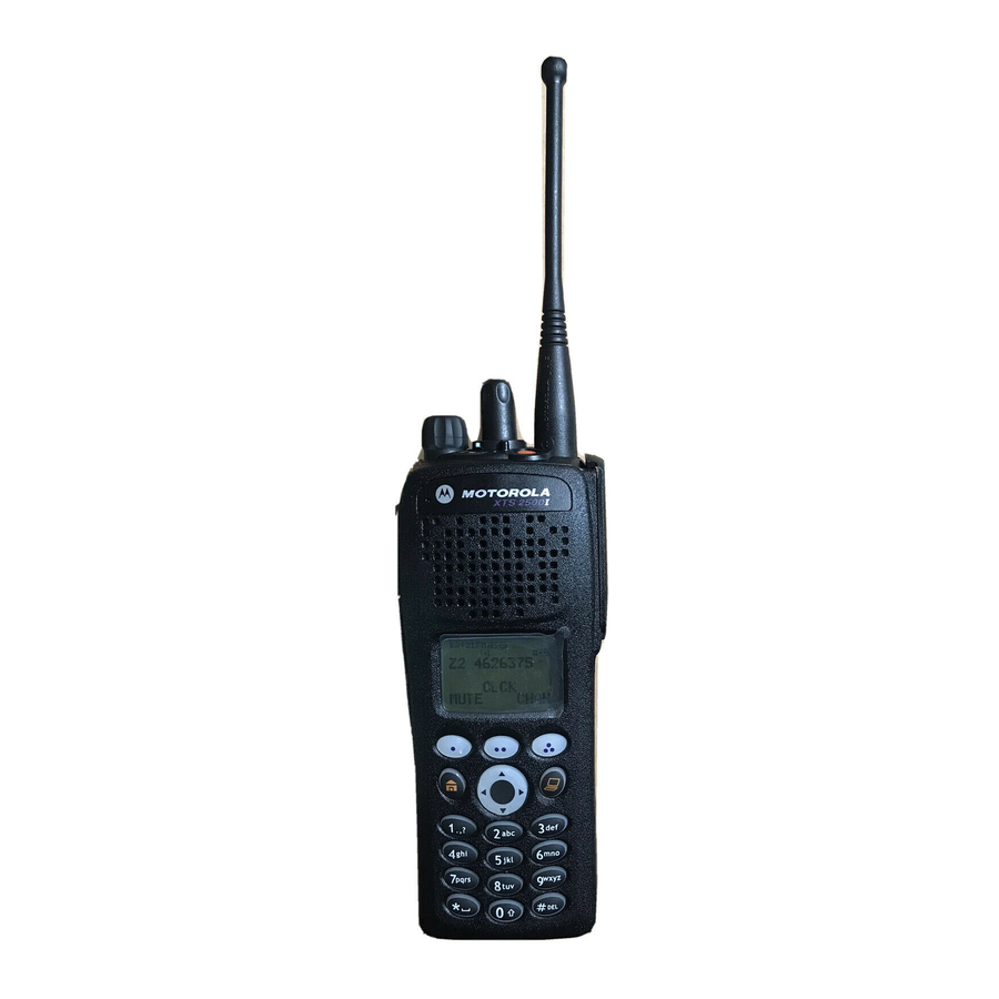
Page 15: Physical Features Of The Xts 2500 Model I Radio
Physical Features of the XTS 2500 Model I Radio Item Antenna Top Button (programmable) Speaker Universal Connector 16-Position Knob (programmable) 3-Position Concentric Switch (programmable) ASTRO XTS 2500 Model I General Radio Operation Page Item On/Off/Volume Control Knob Microphone 10 Top Side (Select) Button (programmable) 11 Push-to-Talk... -
Page 16: Programmable Features
General Radio Operation Programmable Features The programmable controls on your radio can be programmed by a qualified technician to operate certain software-activated features. The features that can be assigned to these controls, and the page numbers where these features can be found, are listed below. Table 1: Programmable Features Feature Call Response... -
Page 17: Led Indicators
LED Indicators This LED Color: RED (Non-flashing) RED (Flashing) GREEN (Flashing) Alert Tones Your radio uses alert tones to inform you of radio conditions. You hear: Tone Name Invalid Key-Press Radio Self-Test Short, Failed Low-Pitched Reject Tone Time-Out Timer Warning ASTRO XTS 2500 Model I Table 2: LED Indicators indicates:... - Page 18 General Radio Operation Table 3: Alert Tones (Continued) You hear: Tone Name No ACK Received Time-Out Timer Timed Out Talk Prohibit/ PTT Inhibit Long, Low-Pitched Out-of-Range Tone Invalid Mode Individual Call Warning Tone A Group of Busy Low-Pitched Tones (Busy Tone) Valid Key-Press Radio Self-Test...
- Page 19 Table 3: Alert Tones (Continued) You hear: Tone Name Volume Set Long, Medium- Emergency Exit Pitched Tone Failsoft Automatic Call Back when the voice channel is A Group of Talk Permit Medium- Pitched Tones Console Acknowledge Received Individual Call Short, High- Low-Battery Chirp Pitched Tone (Chirp)
-
Page 20: Standard Accessories
Prior to using a new battery, charge it for a minimum of 16 hours to ensure optimum capacity and performance. For a list of Motorola approved batteries available for use with your XTS 2500 radio, see “Batteries” on page 43. - Page 21 Attach the Battery With the radio off, fit the three extensions at the bottom of the battery into the bottom slots on the radio. Press the top of the battery against the radio until both latches click into place. Remove the Battery With the radio off, slide down the latches on the sides of the battery.
-
Page 22: Antenna
General Radio Operation Antenna For information regarding other available antennas, see page 43. Attach the Antenna With the radio off, turn the antenna clockwise to attach Remove the Antenna With the radio off, turn the antenna counter-clockwise to remove it. -
Page 23: Belt Clip
Belt Clip Attach the Belt Clip Align the grooves of the belt clip with those of the battery. Press the belt clip downward until you clear a “click.” Remove the Belt Clip Use a flat-bladed object to press the belt clip tab away from the battery. -
Page 24: Universal Connector Cover
General Radio Operation Universal Connector Cover The universal connector cover is located on the antenna side of the radio. It is used to connect certain accessories to the radio. Note: To prevent damage to the connector, shield it with the connector cover when not in use. -
Page 25: Remote Speaker Microphone Adapter
Attach the Adapter With the Motorola side of the adapter facing out, snap the smaller end of the adapter into place in the shroud indent, below the On/Off Volume Control Knob. -
Page 26: Radio On And Off
General Radio Operation Radio On and Off Turn the Radio On Turn the On/Off/Volume Control knob clockwise. • If the test is successful, you hear a medium- pitched tone. • If the test is unsuccessful, you hear a low-pitched tone. Turn off the radio, check the battery, and turn the radio on. -
Page 27: Zones And Channels
Zones and Channels A zone is a grouping of channels. A channel is a group of radio char- acteristics, such as transmit/receive frequency pairs. Before you use your radio to receive or send messages, you should select the zone. Select a Zone If a control on your radio has been preprogrammed as the Zone switch, move the Zone... -
Page 28: Receive / Transmit
General Radio Operation Receive / Transmit Radio users who switch from analog to digital radios often assume that the lack of static on a digital channel is an indication that the radio is not working properly. This is not the case. Digital technology quiets the transmission by removing the “noise”... -
Page 29: Use The Preprogrammed Volume Set Button
Use the Preprogrammed Volume Set Button Turn the radio on and select the desired zone and channel. See Turn the Radio On, page 14 and Zones and Channels, page Press and hold the Volume Set button to hear the volume set tone. Release the Volume Set button. -
Page 30: Use The Preprogrammed Monitor Button
General Radio Operation Use the Preprogrammed Monitor Button Turn the radio on and select the desired zone and channel. Press the Monitor button and listen for activity. (See the following Conventional Mode Operation.) Adjust the Volume Control knob if necessary. Press and hold the PTT button to transmit. -
Page 31: Conventional Mode Operation
Conventional Mode Operation Your radio may be programmed to receive Private-Line® (PL) calls. Momentarily press the Monitor button to listen for activity. Press and hold the Monitor button to set continuous monitor operation. (The duration of the button press is programmable.) Press the Monitor button again, or the PTT button, to return to the original squelch... - Page 32 General Radio Operation Notes...
-
Page 33: Common Radio Features
Common Radio Features Selectable Power Level This feature lets you select the power level at which your radio will transmit. The radio will always turn on to the preprogrammed default setting. This feature must be programmed by a qualified radio technician. -
Page 34: Time-Out Timer
Common Radio Features Time-out Timer The time-out timer turns off your radio’s transmitter. The timer is set for 60 seconds at the factory, but it can be programmed from 0 to 7.75 minutes (465 seconds) by a qualified radio technician. Hold down the PTT longer than the programmed time. -
Page 35: Emergency
Emergency If the top (orange) button is programmed to send an emergency signal, then this signal overrides any other communication over the selected channel. Your radio can be programmed for the following: • Emergency Alarm • Emergency Alarm with Emergency Call •... -
Page 36: Send An Emergency Alarm
Common Radio Features Send an Emergency Alarm An Emergency Alarm will send a data transmission to the dispatcher, identifying the radio sending the emergency. With your radio turned on, press the Emergency button. The red LED lights, and you hear a short, medium-pitched tone. -
Page 37: Send A Silent Emergency Alarm
Send a Silent Emergency Alarm With your radio turned on, press the Emergency button. The LED does not light, and you hear no tones. Note: To exit emergency at any time, press and hold the Emergency button for about a second. The silent emergency state continues until you: Press and hold the... - Page 38 Common Radio Features Release the PTT button to end the transmission and wait for a response from the dispatcher. Press and hold the Emergency button for about a second to exit emergency. The radio operates in the normal dispatch manner while in Emergency Call, except, if enabled, it will return to one of the following: Using this operation:...
-
Page 39: Emergency Keep-Alive
Common Radio Features Emergency Keep-Alive With Emergency Keep-Alive enabled, if the radio is in the Emergency state, you cannot turn off the radio by using the On/Off Volume Control knob. With Keep-Alive, the radio will only exit the Emergency state using one of the ways mentioned in the previous sections (Emergency Alarm, Silent Emergency Alarm, or Emergency Call). -
Page 40: Scan
Common Radio Features Scan The scan feature allows you to monitor traffic on different channels by scanning a preprogrammed list of channels. The list must be preprogrammed by a qualified technician. Turn Scan On and Off Use the Preprogrammed Scan On/Off Switch Place the Scan On/Off Switch in the “scan on”... -
Page 41: Conventional Scan Only
Conventional Scan Only Make a Dynamic Priority Change While the radio is scanning, the dynamic priority change feature lets you temporarily change any channel in a scan list (except the priority- one channel) to the priority-two channel. The replaced priority-two channel becomes a non-priority channel. -
Page 42: Telephone Calls (Trunking Only)
Common Radio Features Telephone Calls (Trunking Only) Use your radio to receive standard phone calls. A landline phone can be used to call a radio. Answer a Phone Call Use the Preprogrammed Call Response Button When a phone call is received you hear telephone-type ringing and the LED flashes GREEN. -
Page 43: Private Calls (Trunking Only)
Private Calls (Trunking Only) These one-to-one calls between two radios are not heard by others in the current talkgroup. Answer a Private Call Use the Preprogrammed Call Response Button. When a private call is received you hear two alert tones and the LED flashes GREEN. -
Page 44: Call Alert Paging
Common Radio Features Call Alert Paging Call Alert allows your radio to work like a pager. Answer a Call Alert Page When a Call Alert Page is received, you hear four repeating alert tones and the LED flashes GREEN. Press and hold the PTT button to talk, release it to listen. -
Page 45: Repeater Or Direct Operation
Repeater or Direct Operation Also known as TALKAROUND operation, DIRECT lets you bypass the repeater and connect directly to another radio. The transmit and receive frequencies are the same. REPEATER operation increases the radio’s range by connecting with other radios through a repeater. Transmit and receive frequencies are different. - Page 46 Common Radio Features Notes...
-
Page 47: Special Radio Features
Special Radio Features Trunking System Controls Failsoft The failsoft system ensures continuous radio communications during a trunked system failure. If a trunking system fails completely, the radio goes into failsoft operation, and automatically switches to its failsoft channel. During failsoft operation: •... -
Page 48: Site Lock
Special Radio Features Site Lock This feature allows your radio to lock onto a specific site and not roam among wide-area talkgroup sites. This feature should be used with caution, since it inhibits roaming to another site in a wide-area system. -
Page 49: Helpful Tips
Helpful Tips Radio Care Cleaning To clean the external surfaces of your radio: Combine one teaspoon of mild dishwashing detergent to one gallon of water (0.5% solution). Apply the solution sparingly with a stiff, non-metallic, short- bristled brush, making sure excess detergent does not get entrapped near the connectors, controls or crevices. -
Page 50: Service
Helpful Tips Service Proper repair and maintenance procedures will assure efficient operation and long life for this product. A Motorola maintenance agreement will provide expert service to keep this and all other communication equipment in perfect operating condition. A nationwide service organization is provided by Motorola to support maintenance services. -
Page 51: Battery
25% discharge, will last even longer. Charging the Battery Motorola batteries are designed specifically to be used with a Motorola charger and vice-versa. Charging in non-Motorola equipment may lead to battery damage and void the battery warranty. -
Page 52: Battery Recycling And Disposal
Motorola fully endorses and encourages the recycling of NiCd batteries. In the U.S. and Canada, Motorola participates in the nationwide Rechargeable Battery Recycling Corporation (RBRC) program for NiCd battery collection and recycling. Many retailers and dealers participate in this program. -
Page 53: Antenna
Antenna Radio Operating Frequencies Before installing the antenna, make sure it matches your radio’s operating frequency. Antennas are frequency sensitive and are color coded according to their frequency range. The color code indicator is located in the center of the antenna’s base. - Page 54 Helpful Tips Antenna Type 800 MHz whip, halfwave 800 MHz dipole 800 MHz stubby, quarterwave 700/800 MHz whip Approx. Insulator Length Color Code 178 RED 200 RED WHITE 178 GREEN Frequency Antenna Range Kit No. (MHz) 806–870 NAF5037 806–870 NAF5039 806–870 NAF5042 764–870...
-
Page 55: Accessories
Accessories Motorola provides the following approved accessories to improve the productivity of your XTS 2500 portable two-way radio. For a list of Motorola-approved antennas, batteries, and other accessories, visit the following web site which lists approved accessories: http://www.motorola.com/cgiss/index.shtml Antennas NAD6563 VHF whip (136–174 MHz) -
Page 56: Carry Accessories
Accessories Carry Accessories Belt Clips HLN6853 Belt clip, 2 1/4 inch Body-Worn NNTN4115 Carrying case, leather with 3-in. swivel belt loop and T-strap NNTN4116 Carrying case, leather with 2.5-in. swivel belt loop and T-strap NNTN4117 Carrying case, leather with 3-in. belt loop and T-strap NLN6349 Shoulder strap for carrying radio NTN5243... -
Page 57: Enhanced And Multi-Unit Line Cords
NTN1667 Tri-chemistry, 110V NTN1668 Tri-Chemistry, 220V Single Unit Charger (2 Prong Euro Plug) NTN1669 Tri-chemistry, 230V NTN1873 IMPRES™ rapid charger 110V single-unit NTN1874 IMPRES™ rapid charger 220V single-unit NTN1875 IMPRES™ rapid charger 240V single-unit NTN4796 Multi-unit, tri-chemistry, rapid rate, 110V NTN7209 Single-unit dual rate, rapid charger w/o cord Enhanced and Multi-Unit Line Cords... -
Page 58: Surveillance Accessories
Accessories Surveillance Accessories Adapters and Adapter Cable BDN6673 Headset adapter cable (for use with BDN6635 and BDN6645) BDN6676 Jedi adapter NTN8613 Surveillance accessory adapter ® CommPort Integrated Microphone/Receivers NTN1624 CommPort with palm PTT NTN1625 CommPort ear mic with PTT for noise levels up to 100 dB (requires BDN6676 adapter) NTN1663 CommPort ear mic with ring PTT for noise levels up... -
Page 59: Headsets And Headset Accessories
BDN6670 Earpiece, mic and PTT separate with extra-loud ear- phone (exceeds OSHA limits), beige BDN6677 Ear mic, standard, noise up to 95 dB (must order BDN6671 interface module), black BDN6678 Ear mic, standard, noise up to 95 dB (must order BDN6671 interface module), beige BDN6719 Earpad, with 3.5mm threaded plug... -
Page 60: Radio Interface Modules For Ear Microphones
Accessories NMN6258 Over-the-head headset with in-line PTT NMN6259 Medium-weight, dual headset with NC mic RMN4049 Jedi “TEMCO” temple transducer Radio Interface Modules for Ear Microphones BDN6671 Push-to-talk (PTT) and voice-activated (VOX) inter- face module (for use with BDN6641, BDN6677 and BDN6678) BDN6708 PTT interface module (for use with BDN6641,... -
Page 61: Appendix: Maritime Radio Use In The Vhf Frequency Range
Appendix: Maritime Radio Use in the VHF Frequency Range Special Channel Assignments Emergency Channel If you are in imminent and grave danger at sea and require emergency assistance, use VHF Channel 16 to send a distress call to nearby vessels and the United States Coast Guard. Transmit the following information, in this order: “MAYDAY, MAYDAY, MAYDAY.”... -
Page 62: Non-Commercial Call Channel
Appendix: Maritime Radio Use in the VHF Frequency Range Non-Commercial Call Channel For non-commercial transmissions, such as fishing reports, rendezvous arrangements, repair scheduling, or berthing information, use VHF Channel 9. Operating Frequency Requirements A radio designated for shipboard use must comply with Federal Communications Commission Rule Part 80 as follows: •... - Page 63 Appendix: Maritime Radio Use in the VHF Frequency Range Table A-1: VHF Marine Channel List (Continued) Channel Number 13** 15** 17** ASTRO XTS 2500 Model I Frequency (MHz) Transmit 156.400 156.450 156.500 156.550 156.600 156.650 156.700 156.750 156.800 156.850 156.900 156.950 157.000 157.050...
- Page 64 Appendix: Maritime Radio Use in the VHF Frequency Range Table A-1: VHF Marine Channel List (Continued) Channel Number 67** 77** Simplex channels 3, 21, 23, 61, 64, 81, 82, and 83 cannot be lawfully used by the general public in US waters. ** Low power (1 W) only *** Guard band Note: A –...
-
Page 65: Glossary
Glossary This is a list of specialized terms used in this manual. Active Channel Analog Signal ASTRO 25 Trunking Motorola standard for wireless digital trunked ASTRO Conventional Call Alert Carrier Squelch Central Controller Channel Control Channel Conventional ASTRO XTS 2500 Model I Acknowledgment of communication. - Page 66 Glossary Digital Private Line (DPL) Digital Signal Dispatcher Dynamic Regrouping Failsoft Hang Up Monitor Network Access Code NiCd NiMH A type of coded squelch using data bursts. Similar to PL except a digital code is used instead of a tone. An RF signal that has a pulsed, or discrete nature, rather than a continuous nature.
- Page 67 Non-tactical/Revert The user will talk on a preprogrammed Page Personality Preprogrammed Private (Conversation) Call Private Line (PL) Programmable Radio Frequency (RF) Repeater Selective Switch ASTRO XTS 2500 Model I emergency channel. The emergency alarm is sent on this same channel. A one-way alert, with audio messages.
- Page 68 Glossary Squelch Standby Tactical/Non-revert Talkaround Talkgroup Trunking Zone Special electronic circuitry added to the receiver of a radio which reduces, or squelches, unwanted signals before they are heard in the speaker. An operating condition whereby the radio’s speaker is muted but still continues to receive data.
-
Page 69: Commercial Warranty
ASTRO XTS 2500 Portable Units Product Accessories Motorola, at its option, will at no charge either repair the Product (with new or reconditioned parts), replace it (with a new or reconditioned Product), or refund the purchase price of the Product during the warranty period provided it is returned in accordance with the terms of this warranty. - Page 70 Product item serial number) in order to receive warranty service and, also, deliver or send the Product item, transportation and insurance prepaid, to an authorized warranty service location. Warranty service will be provided by Motorola through one of its authorized warranty service locations. If you first contact the company...
- Page 71 Product, it can facilitate your obtaining warranty service. You can also call Motorola at 1-888-567-7347 US/Canada. V. WHAT THIS WARRANTY DOES NOT COVER: A) Defects or damage resulting from use of the Product in other than its normal and customary manner.
- Page 72 A) that MOTOROLA will be notified promptly in writing by such purchaser of any notice of such claim; B) that MOTOROLA will have sole control of the defense of such suit and all negotiations for its settlement or compromise; and C) should the Product or parts become, or in MOTOROLA’s...
- Page 73 Commercial Warranty the use of ancillary equipment or software not furnished by MOTOROLA which is attached to or used in connection with the Product. The foregoing states the entire liability of MOTOROLA with respect to infringement of patents by the Product or any parts thereof.
- Page 74 Commercial Warranty Notes...
-
Page 75: Index
Index accessories antennas ...43 batteries ...43 belt clips ...44 body-worn ...44 carry accessories ...44 chargers ...44 Commport integrated microphone/ receivers ...46 earpieces ...46 headsets ...47 microphones, remote speaker .45 radio interface modules ...48 switches ...48 alert tones ...5 analog squelch ...21 answer a private call ...31 antenna attach the antenna ...10... - Page 76 Index radio care cleaning ...37 handling ...37 receive / transmit use the preprogrammed monitor button ...18 use the preprogrammed volume set button ...17 without using the volume set and monitor buttons ...16 remote speaker microphone adapter attach the adapter ...13 remove the adpater ...13 repeater or direct operation ...33 repeater/direct switch ...33...
- Page 78 Motorola, Inc. 8000 West Sunrise Boulevard Ft. Lauderdale, FL 33322 MOTOROLA, the Stylized M Logo, ASTRO and CommPort are registered in the U.S. Patent and Trademark Office. All other product or service names are the property of their respective owners.