ADTRAN H2TU-C Quick Manual
For litespan using narrowband pairs
Hide thumbs
Also See for H2TU-C:
- Installation and maintenance practice (68 pages) ,
- Installation and maintenance manual (26 pages) ,
- Job aid (2 pages)
Advertisement
Quick Links
HDSL2
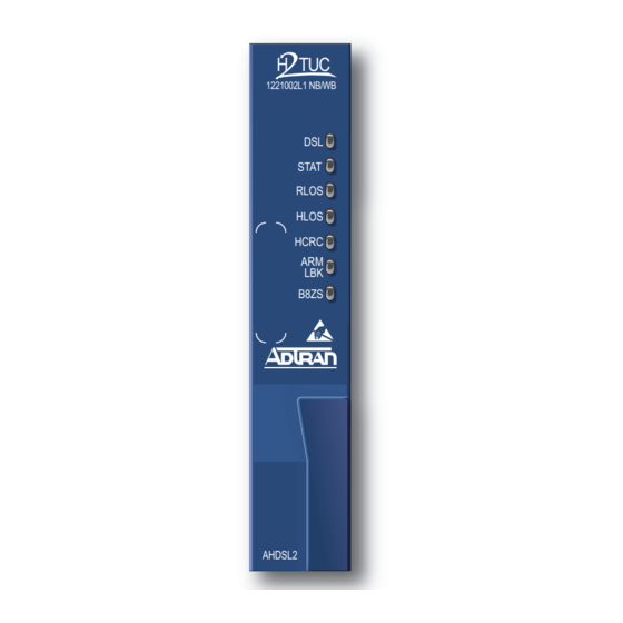
FRONT PANEL LEDS
H2TU-C
Label
P/N: 1221002L2
DSL
CLEI: SLL5R36G_ _
STAT
H TUC
1221002L2 NB
RLOS
DSL
HLOS
STAT
RLOS
HCRC
HLOS
HCRC
ARM
ARM/
LBK
LBK
B8ZS
B8ZS
INSTALLATION
After unpacking the unit, inspect it for damage. If damage is noted, file a claim
with the carrier and then contact ADTRAN. Refer to Warranty.
Follow the steps below to install the H2TU-C for Litespan:
1. If present, remove the Access Module Blank from the appropriate access
module slot of the chassis.
2. Pull the ejector latch, located on the lower right-hand side of the H2TU-C
for Litespan front panel, from its closed position.
3. Hold the H2TU-C for Litespan by the front panel while supporting the
AHDSL2
bottom edge of the module with the ejector latch opened to engage the
chassis edge. Align the module edges to fit in the lower and upper guide
grooves for the access module slot.
4. Slide the module into the access module slot. Simultaneous thumb pressure
at the top and at the bottom of the module ensures that the module is firmly
positioned against the backplane of the chassis. Secure the module in place
C A U T I O N !
by pushing up and in on the ejector latch.
SUBJECT TO ELECTROSTATIC DAMAGE
When installed, the H2TU-C for Litespan runs a series of self-tests. Once the
OR DECREASE IN RELIABILITY.
HANDLING PRECAUTIONS REQUIRED.
self-tests are complete, the status LEDs reflect the true state of the hardware.
©2006 ADTRAN, Inc.
All Rights Reserved.
H2TU-C for Litespan
Status
Description
Green
HDSL2 SNR quality is optimum (6 dB or higher)
Yellow
HDSL2 SNR quality is marginal (1-5 dB)
Red
HDSL2 SNR quality is poor (0 dB)
2
Flashing Red
HDSL2 Pulse Attenuation is >30 dB
Off
Indicates loss of power to the H2TU-R
Green
Normal; HDSL2 synchronization with H2TU-R
2
Flashing Green
Acquiring HDSL2 synchronization with H2TU-R
Red
Failure indication; unable to start/load firmware
Off`
DS1 signal from CPE is present at H2TU-R
Red
DS1 signal from CPE is absent at H2TU-R or
framing does not match
Off
HDSL2 synchronization achieved
Red
HDSL2 loss of synchronization
2
Flashing Red
DC continuity fault detected on HDSL2 loop
Off
No HDSL2 CRC errors within last 30 minutes
Yellow
Four or more HDSL2 CRC errors in last 30 minutes
Red
HDSL2 CRC errors are being detected
Off
No loopback active
Green
Loopback is active on this module
Yellow
Module is armed but loopback is not active
Off
AMI line code
Green
B8ZS line code
For more information, refer to the Installation and Maintenance Practice (P/N 61221002L1-5) available online at www.adtran.com.
HDSL2
Using Narrowband Pairs
®
TROUBLESHOOTING GUIDE
Condition
Solution
Power up: all
1. Verify that the channel bank or ONU BPS power LEDs are on.
front panel
2. Make sure that unit is fully and correctly inserted into the channel bank or ONU.
indicators off
3. If step 1 fails, contact Alcatel customer service (800-848-0333). If step 1 passes,
but step 2 fails, replace the H2TU-C.
LED
1. Verify that the channel bank or ONU BPS power LEDs are on.
STAT
Red.
2. Verify that the equipment type for the Litespan H2TU-C slot is AHDSL2. Using
TL1, equipment type is shown with the command rtrv-eqpt::AID, where AID is
the access identifier (i.e., cot-1-15).
3. If step 1 fails, contact Alcatel customer service. If step 1 and step 2 pass, replace
the H2TU-C. If step 1 passes but step 2 fails, delete the equipment record (i.e.,
dlt-eqpt::cot-1-15 with TL1) and reinsert the card, or equip the slot with the
currently reserved equipment type.
LED
1. Confirm that the HDSL2 loop is not open.
STAT
off;
HLOS
2. Confirm that the HDSL2 loop is not shorted.
LED Red
3. Verify the loop conforms to CSA guidelines and is not too long. Loop loss at 196
kHz should be less than 35 dB.
4. Verify that the HDSL2 loop has acceptable noise limits.
5. Verify that tip and ring of each HDSL2 loop belongs to the same twisted pair.
6. If steps 1 through 5 pass, but the
7. If step 6 fails, replace the H2TU-R.
LED
1. Check that framing line coding are set appropriately for T1 data at the H2TU-R.
STAT
off;
RLOS
2. Check that the
LED Red.
3. If step 1 fails, change the appropriate framing and line coding. If step 1 passes,
but step 2 fails, a problem may exist at the H2TU-R T1 interface. If the problem
does not exist at the T1 interface, replace the H2TU-C.
CARD EDGE PINOUT
ADTRAN uses negative ground-referenced span powering voltage (–190 VDC) on the
HDSL2 loop. If desired, disable H2TU-R span powering to allow locally powered H2TU-R
applications.
H2TU-C for Litespan plugs directly into a Litespan channel bank assembly channel unit slot.
Litespan system software must be version 11.0.0 or higher. The tip and ring connections
from the H2TU-C to the shelf are made through card edge pins A3 (Narrowband Tip) and A4
(Narrowband Ring).
H2TU-C for Litespan supports narrowband cabling on the Litespan RT shelf. For more
information regarding the cabling, refer to Alcatel document OSP 363-405-270.
COMPLIANCE
Code
Power Code (PC)
Telecommunication Code (TC)
Installation Code (IC)
61221002L2-22E
LED remains red, replace the H2TU-C.
HLOS
LED at the H2TU-R is off.
RLOS
Input
Output
F
C
–
X
A
–
0612
Advertisement

Related Manuals for ADTRAN H2TU-C


Summary of Contents for ADTRAN H2TU-C
- Page 1 Litespan system software must be version 11.0.0 or higher. The tip and ring connections for Litespan front panel, from its closed position. from the H2TU-C to the shelf are made through card edge pins A3 (Narrowband Tip) and A4 (Narrowband Ring).
- Page 2 5. If NIU is enabled, then the H2TU-R can be in network loopback when the H2TU-C or H2R loop up codes are sent. Warranty: ADTRAN will replace or repair this product within the warranty period if it does not meet its published specifications or fails while in service.