Agilent Technologies 490 Micro GC Field Casen User Manual
Hide thumbs
Also See for 490 Micro GC Field Casen:
- Installation instructions manual (8 pages) ,
- User manual (37 pages) ,
- Installation and configuration (2 pages)
Table of Contents
Advertisement
Quick Links
Advertisement
Table of Contents

Related Manuals for Agilent Technologies 490 Micro GC Field Casen


Summary of Contents for Agilent Technologies 490 Micro GC Field Casen
- Page 1 Agilent 490 Micro GC Field Case User Manual Agilent Technologies...
- Page 2 Further, to the max- agreement and written consent from imum extent permitted by applicable Agilent Technologies, Inc. as governed by Safety Notices law, Agilent disclaims all warranties, United States and international copyright either express or implied, with regard laws.
-
Page 3: Table Of Contents
Contents Getting Started Safety Information Initial Inspection Unpacking Packing list Carrier gas Instrument Overview Front view Back view Power source Battery pack Installation and Use Connecting the Micro GC to the Field Case Automatic Battery Selection Battery Status LED Internal Buzzer Carrier Gas Refill Instructions Carrier gas refill assembly Refill procedure... - Page 4 Operation Cleaning Disposal instructions Technical specifications 490 Micro GC Field Case User Manual...
-
Page 5: Getting Started
AgilentProduct Name Variable 490 Micro GC Field Case Getting Started Safety Information Initial Inspection Unpacking Instrument Overview Agilent Technologies... -
Page 6: Safety Information
If you have any problems understanding the text in this manual, we advise you to contact your Agilent Technologies service office for assistance. Agilent Technologies, Inc. cannot accept responsibility for any damage or injury caused by misunderstanding of the information in this manual. - Page 7 Getting Started Follow these safety practices to ensure safe equipment operation: • Perform periodic leak checks on all supply lines and pneumatic plumbing. • Do not allow gas lines to become kinked or punctured. Place lines away from foot traffic and extreme heat or cold. •...
- Page 8 This unit has been designed and tested in accordance with recognized safety standards and designed for use indoors. • If the instrument is used in a manner not specified by Agilent Technologies, the protection provided by the instrument may be impaired. •...
-
Page 9: Initial Inspection
Inspect the cartons carefully for damage or signs of rough handling. Report damage to the carrier and to your local Agilent Technologies, Inc. office. Unpack the Micro GC Field Case and accessories carefully and transfer to the work area, using proper handling techniques. -
Page 10: Unpacking
Getting Started Unpacking Check the packing list to ensure you have received all that you require. Packing list Micro GC Field Case Accessories (optional) Table 1 Accessories Car cigarette lighter adapter CP740291 Charger for 12 V battery pack NiMH CP740427 Battery pack NiMH CP740328... -
Page 11: Instrument Overview
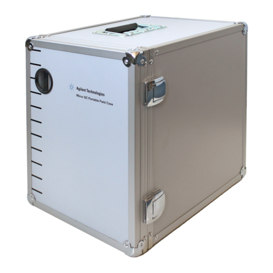
Figure 2 Micro GC Field Case For problems or questions about your Micro GC Field Case, please contact your nearest Agilent Technologies, Inc. representative. 490 Micro GC Field Case User Manual... -
Page 12: Front View
Getting Started Front view Carrier 1 Carrier gas pressure Battery status Fill 1 Gas fill connector Valve 1 Carrier gas open/close valve Battery compartment Figure 3 Front view For more information on the Battery status see “Battery Pack” on page 30. For more information on the Carrier 1 and Fill 1 see “Carrier Gas Refill Instructions”... -
Page 13: Back View
Getting Started Back view Carrier 1 Carrier gas connection to Micro GC Power connector Power IN male connector (Un)lock screw (Un)locking the Field Case interior Figure 4 Back view Power source • Voltage of 12 Vdc, 150 W • Only use the power supply (p/n CP742999) provided with the Micro GC. -
Page 14: Battery Pack
Getting Started Battery pack The Micro GC Field Case is equipped with a 12 V 10 Ah (ampere-hours) Ni-MH (Nickel metal hydride) battery. See Chapter 3 “Battery Pack and Charger” on page 29 for more details. Depending on the condition in which the Micro GC is used, the battery will provide power up to 8 hours before recharging becomes necessary. -
Page 15: Installation And Use
AgilentProduct Name Variable 490 Micro GC Field Case Installation and Use Connecting the Micro GC to the Field Case Automatic Battery Selection Battery Status LED Internal Buzzer Carrier Gas Refill Instructions Shipping Cleaning Disposal Agilent Technologies... -
Page 16: Connecting The Micro Gc To The Field Case
Installation and Use Connecting the Micro GC to the Field Case Loosen the screw at the back of the Field Case. Figure 5 Screw to loosen Remove the Field Case interior by gently pulling at the handgrip. Figure 6 Handgrip to remove interior Do not install the batteries or charge the carrier gas tank until all parts WA R N I N G are fully assembled and reinstalled inside the Field Case. - Page 17 Installation and Use Place the interior on a flat table and rotate 90° counter clockwise. Un-rotated interior Rotated interior Figure 7 Rotate the interior Place the Micro GC on the Field Case interior. Figure 8 Placing the Micro GC Screw the Micro GC and the interior together with the two Torx-T20 screws.
- Page 18 Installation and Use Figure 9 Location of screws Set the interior horizontal. At the back of the interior, attach the power connector. Figure 10 Squeeze the connector then push in 490 Micro GC Field Case User Manual...
- Page 19 Installation and Use Using the included tubing (situated in the battery compartment), connect the Carrier in (at the Micro GC) with Carrier 1 (on the Field Case interior). Figure 11 Tubing location Connect the communication cable inside the Micro GC. See the Micro GC user manual.
- Page 20 Installation and Use Slide the interior back into the Field Case and lock it with the (Un)lock screw. Figure 13 Location of the lock screw Connect the Micro GC to the sample source. For details, see the Micro GC user manual. At the front of the Field Case, open the battery compartment by unscrewing the nuts.
- Page 21 Installation and Use Slide the battery(s) in the compartment and connect the battery(s) to the system (in case of one battery, connect the cable labeled battery 1). The fan at the back and the two LEDs at the front will be activated for a few seconds indicating the electronics are testing and are ready.
-
Page 22: Automatic Battery Selection
Installation and Use Figure 16 The door lock Automatic Battery Selection During startup, the system will check how many batteries are available and choose the one which is most charged. Only one battery at a time (when two batteries are present) will be used to power the Micro GC. -
Page 23: Battery Status Led
Installation and Use Battery Status LED The two green LEDs in the front of the Field Case indicate the battery status. Status Description System working Blinking System working but battery needs to be recharged Micro GC is OFF Internal Buzzer The buzzer is located in the Field Case and gives information about the battery status. -
Page 24: Carrier Gas Refill Instructions
Installation and Use Carrier Gas Refill Instructions Carrier gas refill assembly Your Micro GC Field Case is equipped with a refillable, high pressure carrier supply tank(s) which has been approved to 12,000 kPa, and has an internal volume of 300 cc. When the instrument is in use, the pressure should not drop in the red area since the Micro GC needs at least 550 ±... -
Page 25: Refill Procedure
This special tool is connected directly to the valve on the gas supply cylinder. Because this connection differs from country to country, Agilent Technologies, Inc. offers a range of Refill Assembly’s to meet all major standards. If the connector of this device, despite a careful choice, does not match your supply unit, ask your local gas supplier for the right part. -
Page 26: Additional Refill Information
Installation and Use When the Refill Assembly has been sufficiently purged, tighten the Fill 1(2) nut. While watching the pressure gauge on the Refill Assembly, slightly open the refill valve. When the pressure on the gauge reads 10,000 to 12,000 kPa, close both valves on the Refill Assembly and the gas supply cylinder. - Page 27 Installation and Use Turn the Valve 1(2) to Open, relieve pressure in the carrier gas cylinder, and close the valve. Purge this way at least twice, do not close the valve the last time, but reconnect the removed tubing. While watching the pressure gauge on the Refill Assembly, slightly open the refill valve.
-
Page 28: Shipping
Installation and Use Shipping If the Micro GC Field Case must be sent back to the factory, it is very important to follow these shipping instructions: Relieve the pressure completely from the internal carrier gas cylinder(s) WA R N I N G according to transportation rules. -
Page 29: Battery Pack And Charger
AgilentProduct Name Variable 490 Micro GC Field Case Battery Pack and Charger Battery Pack Battery Charger Agilent Technologies... -
Page 30: Battery Pack
Micro GC. Figure 19 Battery Pack (p/n CP740328) General precautions It is the responsibility of the Customer to inform Agilent Technologies WA R N I N G Customer Support Representatives if this battery has been used in com-... -
Page 31: Battery Location
Battery Pack and Charger Battery location The Ni-MH rechargeable battery(s) is located in the front of the Field Case in a specially designed compartment. Battery compartment Figure 20 The battery compartment Open the compartment by squeezing the two clips together. Figure 21 Unscrew the nuts 490 Micro GC Field Case User Manual... -
Page 32: Battery Handling
Battery Pack and Charger The battery(s) will be visible. Figure 22 Slide out the battery The battery(s) can be removed by unplugging the connector and slightly pulling the battery(s) out of the compartment. Battery handling • Never disassemble the battery as the electrolyte inside is strong alkaline and can damage skin and clothes. -
Page 33: Charging
• Batteries should always be charged prior to use. Be sure to charge correctly, and use only the battery charger that has been supplied by Agilent Technologies, Inc. • Ambient temperature affects charging efficiency. As charging efficiency is best within a temperature range of 10 °C to 40 °C, when charging, be sure the Battery Pack and charger... -
Page 34: Discharging
• Do not charge the battery if there is a possibility of any kind of electrical damage. Instead, disconnect the battery power cords and contact your Agilent Technologies office. Discharging Since over-discharging (deep discharge) damages the battery characteris-... -
Page 35: Battery Service Life
Battery Pack and Charger Battery service life Batteries used under proper conditions of charging and discharging can be used 500 cycles or more. Batteries are chemical products involving internal chemical reactions. Performance deteriorates not only with use but also during prolonged storage. Normally, a battery will last two years (or 500 cycles) if used under proper conditions and not overcharged or overdischarged. -
Page 36: Technical Specifications
Battery Pack and Charger Technical specifications Table 3 Battery Pack technical specifications Technology Ni-MH (Nickel Metal Hydride) Number of cells Cell-orientation 1 × 10 in row Nominal output voltage 12 Vdc Capacity 10000 mAh Protection Built-in thermo fuse resettable (75 °C) and current (14 A) Output cable Two wires, UL1015 approved... -
Page 37: Battery Charger
Battery Pack and Charger Battery Charger Introduction This Charger (p/n CP740427), Figure 23, must only be used in combination with the Micro GC Battery Pack (CP740328), see Figure 19 on page 30. This Charger is tailored to meet the power needs of the Battery Pack. -
Page 38: Charger Status
Battery Pack and Charger Charger status Status Yellow Battery not connected † Yellow Battery initialization and analysis Orange Fast charge Green with intermittent Yellow flash Top-off charge Green Ready to use and trickle charge Alternating Orange-Green Error * There is power to the charging unit, but the battery is not connected. †... - Page 39 Battery Pack and Charger • If the outer case is dirty (never clean the inside!), clean it with a soft, clean cloth dampened with mild detergent. • Never use alcohol or thinners to clean the Battery Charger, these chem icals can damage the case. •...
- Page 40 Battery Pack and Charger 490 Micro GC Field Case User Manual...
- Page 42 Agilent Technologies © Agilent Technologies, Inc. 2014 Printed in the Netherlands February 2014 *G3581-90005* G3581-90005...