Advertisement
Quick Links
CHAPTER 1. SPECIFICATION . . . . . . . . . . . . . . . . . . . . . . . . . . . . . . . . . . . . . 1
CHAPTER 2. HARDWARE DESCRIPTION. . . . . . . . . . . . . . . . . . . . . . . . . . . . .
CHAPTER 3. NOTE FOR SERVICING . . . . . . . . . . . . . . . . . . . . . . . . . . . . . . . .
CHAPTER 4. DISASSEMBLY AND ASSEMBLY . . . . . . . . . . . . . . . . . . . . . . . . .
CHAPTER 5. DIAGNOSTICS AND CHECK ITEMS . . . . . . . . . . . . . . . . . . . . . .
CHAPTER 6. CIRCUIT DIAGRAM & PARTS LAYOUT . . . . . . . . . . . . . . . . . . . .
PARTS GUIDE
Parts marked with "!
" is important for maintaining the safety of the set. Be sure to replace these parts with specified
ones for maintaining the safety and performance of the set.
SERVICE MANUAL
CONTENTS
SHARP CORPORATION
CODE: 00ZHC4000SP/E
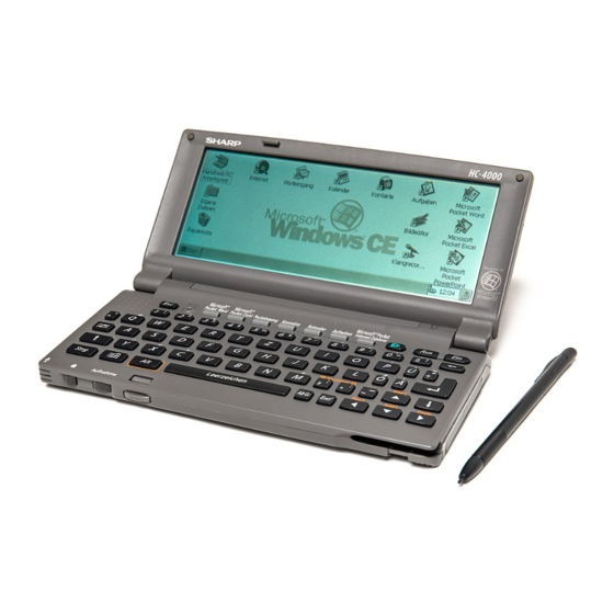
Handheld PC
HC-4000
MODEL
HC-4100
MODEL
This document has been published to be used for
after sales service only.
The contents are subject to change without notice.
Advertisement

Related Manuals for Sharp HC-4000


Summary of Contents for Sharp HC-4000
- Page 1 SERVICE MANUAL CODE: 00ZHC4000SP/E Handheld PC HC-4000 MODEL HC-4100 MODEL CONTENTS CHAPTER 1. SPECIFICATION ........1 CHAPTER 2.
- Page 2 CHAPTER 1. SPECIFICA TION The HC-4000/HC-4100 is a handheld PC using the Microsoft® Win- Memory dows® CE 2.0 operating system, which is very similar to the Mi- 4 MB (HC-4000) crosoft Windows ™ 95 and Windows NT 4.0 operating systems.
- Page 3 Part names and functions PC Card eject switch RESET button Application keys Backup battery cover Display Speaker Backlight key Battery Notification indicator replacement switch Memory module cover Hodem jack OFF key ON key Microphone Main battery holder Serial port DC power jack Infrared port Release button PC Card slot...
- Page 4 SYSTEM CONFIGURATION – 3 –...
- Page 5 1. Turn off the unit. B and S keys B and C keys 2. Resetting the HC-4000/4100 If the unit stops responding while you are using it, you can reset the unit. Make sure the unit is turned on, and then press the RESET button with the stylus.
- Page 6 2. Slide the battery replacement switch to the REPLACE MAIN BAT- Replacing the backup battery TERIES position. 1. Turn off the unit. 2. Slide the battery replacement switch to the REPLACE BACKUP BATTERY position. REPLACE MAIN BATTRIES NORMAL OPERATION REPLACE BACKUP BATTERY REPLACE MAIN BATTRIES NORMAL OPERATION REPLACE BACKUP BATTERY...
- Page 7 About power source 3. Insert the 18-pin end of the supplied serial cable into the serial • port on the unit. You can use two AA alkaline batteries or the optional NiMH Re- chargeable Battery Pack to power your unit, or the AC adaptor included in the optional Docking Station Kit.
- Page 8 Insert the PC Card into the slot as far as it will go. Make sure the PC You can exchange data with other devices such as SHARP ZR Se- Card is facing up. If the card will not go in, check the orientation.
- Page 9 For Explorer files, select a file in step 2. In step 4, tap File , Send To , and Infrared Recipient to send the file. 4. Set the sending unit to the sending mode. In case of SHARP ZR Series unit, press SEND key, then start receiving the data.
- Page 10 1: Trademark Microsoft 3000/3500X. Servicing for the ZR-3000/3500X is performed in the following cases: 2: Supplied by SHARP. In the future, it may be supplied through • the communication network instead of by a floppy disk. When the MAIN PWB unit is replaced.
- Page 11 WRITE: Writing of patch data VERIFY: Verifying patch data (The display is made in an in- stant.) 9. End of patch writing When patch writing is completed, the bar display is cleared. At the same time, the check sum is displayed on the lower right side. Note: The following operations of patch erase, write, and verify should be performed immediately after entering the diag mode by "ON"...
- Page 12 [Note for assembly] CHAPTER 4. DISASSEMBLY AND 1. Memory PWB attachment screw tightening ASSEMBLY 1. memory PWB attachment screw tightening This chapter mainly describes the disassembly procedure. For as- sembly, reverse the disassembly procedures. If any special care is required for assembly, "Note for assembly" is provided. Docking connectors Simple and easy replacement procedures of units and parts are omit- ted.
- Page 13 * Tightening torque is 1.5Kgf ⋅ cm ± 7% 2. Speaker lead wire process 2 Key bottom cabinet removal 1. Remove eight screws 1 and remove key bottom cabinet 2 . Indicator filter Microphone Keep the lead wire away from the parts. 3.
- Page 14 2. Tighten the return spring to the key upper cabinet with 3 Display unit and Main PWB unit removal a screw, then attach the recording/LED indicator re- 1. Remove two screws 1 . lease button. 2. Remove LCD FPC 2 and remove Display unit 3 . 3.
- Page 15 5. Copper foil tape attachment 4 Key PWB unit removal Key cabinet side 1. Remove two screws 1 and remove chassis B 2 . (1) Temporarily attach the copper foil tape to be added to the PWB 2. Remove fourteen screws 3 and remove key PWB unit 4 . unit as shown in the figure below.
- Page 16 3. Remove two screws 5 , pressure angle 6 , and pressure rubber 7 4. Remove tablet unit 8 . 5. Remove LCD unit 9 . Cusion A Cusion B SHARP Badge [Note for assembly] 1. Attachment of tablet spacer to the tablet (Use the jig.) Reference Do not extend.
- Page 17 shape jumper lead Reference Do not extend. Solder Tablet unit Rug terminal LCD unit After cleaning the BL PWB pin section (IPA), Hinge unit fold the tablet unit pin section to the Seg <Fig. 1> Lead wire wiring process As shown in Fig. 2, move the lead wire to the right from the state of Fig.
- Page 18 Soldering of rug terminal and lead wire Rug terminal (QLUGE1005CCZZ) (Note) Do not put solder on this side. Solder 6 Key bottom cabinet disassembly Key bottom cabinet IC Cord cover Spring Speaker IR Filter Battery exchange knob Sheet Battery box lock knob Spring –...
- Page 19 7 Main PWB attachment process – 47 –...
- Page 20 2) Jumper wire cutting/striping dimension Eject unit 85mm +5 -0 mm 1.5mm +5 1.5mm +5 -0 mm -0 mm IC Card electrostatic sheet Fixing sheet B/U Battery term B/U Battery Wire material U/L Style 1571 ILUX term electrical wire AWG28 Ni-HM Battery terminal 3.
- Page 21 COPYRIGHT 1997 BY SHARP CORPORATION All rights reserved. Printed in Japan. No part of this publication may be reproduced, stored in a retrieval system, or transmitted, in any form or by any means, electronic, mechanical, photocopying, recording, or otherwise, without prior written permission of the publisher.