Advertisement
( PN-2940S-A, S-E )
( PN-2940S-B, S-F )
( PN-2940S-C )
( PN-2940S-D )
SPECIFICATIONS
Disc format:
CD-DA, CD-R/RW
Disc:
12cm disc
MP3 mode:
Sampling rate:
MPEG1 ; 32kHz, 44.1kHz, 48kHz
MPEG2 ; 24kHz, 22.05kHz, 16kHz
MPEG2.5; 8kHz, 11.025kHz, 12kHz
Bit rate:
MPEG1 ; 32k to 320kbps/VBR
MPEG2 ; 8k to 160kbps/VBR
MPEG2.5 ; 8k to 160kbps/VBR
Logical Format;
ISO9660 level1, 2
Romeo or Joliet
Clarion Co., Ltd.
7-2, Shintoshin, Chuo-ku, Saitama-shi, Saitama 330-0081 Japan
Service Dept.: 7-2, Shintoshin, Chuo-ku, Saitama-shi, Saitama 330-0081 Japan
Tel: +81-48-601-3705 FAX: +81-48-601-3804
Service Manual
- 1 -
RENAULT Genuine
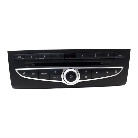
6-disc CD/MP3/WMA Autochanger
With Sub Control Panel Switch
PN-2940S-A
Model
(Genuine No. 28184 JY10A)
(Facial color : Black) (For Korea)
PN-2940S-B
Model
(Genuine No. 28184 JY10B)
(Facial color : Black) (For Korea)
PN-2940S-C
Model
(Genuine No. 28184 JY00A)
(Facial color : Black) (For Europe)
PN-2940S-D
Model
(Genuine No. 28184 JY00B)
(Facial color : Black) (For Europe)
PN-2940S-E
Model
(Genuine No. 28184 JY20A)
(Facial color : Wood type) (For Korea)
PN-2940S-F
Model
(Genuine No. 28184 JY20B)
(Facial color : Wood type) (For Korea)
WMA mode:
Sampling rate:
Ver 7 ; 32kHz, 44.1kHz
Ver 8 ; 32kHz, 44.1kHz
Ver 9 ; 32kHz, 44.1kHz, 48kHz
Bit rate:
48k to 192kbps/VBR
B/U Current consumption:
Less than 0.25mA
Distortion:
Less than 0.2%(20kHz L.P.F.)
Power supply voltage: 13.2V DC(10.8V to 15.6V)
Ground:
Negative
Dimensions(mm):
231.43(W) x 75(H) x 183(D)
Weight:
1.95kg
Published by Service Dept.
298-6539-00 Jan.2008
Printed in Japan
PN-2940S-A,
S-B,C,D,E,F
Advertisement
Table of Contents

Related Manuals for Clarion PN-2940S-A


Summary of Contents for Clarion PN-2940S-A
- Page 1 Service Manual RENAULT Genuine 6-disc CD/MP3/WMA Autochanger With Sub Control Panel Switch PN-2940S-A Model (Genuine No. 28184 JY10A) ( PN-2940S-A, S-E ) (Facial color : Black) (For Korea) PN-2940S-B Model (Genuine No. 28184 JY10B) (Facial color : Black) (For Korea) PN-2940S-C...
-
Page 2: To Engineers In Charge Of Repair Or Inspection Of Our Products
C l a r i o n C o . , L t d M AD E I N H N A Please do not wash the soldering point after soldering. P A R T N O . PN-2940S-A, - 2 - S-B,C,D,E,F... -
Page 3: Troubleshooting
( D401 to D427 ) Check the waveform of Confirm to 10pin of J1 connection of CD mechanism ( TP111 ) Confirm to the output circuit of SPDIF IC1, L4, R26, Q6, Q7, FIL4, L102 PN-2940S-A, - 3 - S-B,C,D,E,F... -
Page 4: Block Diagram
EXPLODED VIEW / PARTS LIST Main section PART NO. DESCRIPTION Q'TY PART NO. DESCRIPTION Q'TY 940-8180-00 ES-ASSY (PN-2940S-A) 310-1841-00 UPPER CASE 940-8180-10 ES-ASSY (PN-2940S-B) 940-8180-20 ES-ASSY (PN-2940S-C) 309-0844-01 ES-PLATE 940-8180-30 ES-ASSY (PN-2940S-D) 331-4305-00 MECH-BRKT(L) 940-8180-42 ES-ASSY (PN-2940S-E) 940-8180-52 ES-ASSY (PN-2940S-F) - Page 5 ×12 ×6 ×19 ×23 PN-2940S-A, - 5 - S-B,C,D,E,F...
-
Page 6: Electrical Parts List
119-0000-05 1/10W 0 ohm JW CCT17 050-0140-63 1/32W 47k ohm x4J 116-2401-15 1/4W 24 ohm CCT18 050-0140-63 1/32W 47k ohm x4J 039-2974-00 PWB(WITHOUT 119-1031-15 1/10W 10k ohm 001-2015-00 RL253 COMPONENT) 119-2711-15 1/10W 270 ohm 001-4100-38 PTZ36 PN-2940S-A, - 6 - S-B,C,D,E,F... - Page 7 117-1021-15 1/8W 1k ohm 073-0778-90 TERMINAL D423 001-7093-92 RFA1112H(ORG) R425 117-1021-15 1/8W 1k ohm VR401 016-7000-00 ROTARY ENCODER D424 001-7093-92 RFA1112H(ORG) R426 117-8211-15 1/8W 820 ohm 039-3065-00 PWB(WITHOUT D425 001-7093-92 RFA1112H(ORG) R427 117-1221-15 1/8W 1.2k ohm COMPONENT) PN-2940S-A, - 7 - S-B,C,D,E,F...
-
Page 8: Printed Wiring Board
1 SYS ON REQ N.C. N.C. N.C. N.C. IR GND N.C. N.C. N.C. Q302 N.C. SHIELD GND R354 N.C. SPDIF GND R358 N.C. R355 SPDIF SIG D303 UART GND N.C. SPDIF GND TP29 TP29 TP101 TP101 PN-2940S-A, - 8 - S-B,C,D,E,F... - Page 9 R402 R405 R403 R406 R404 * Difference SOLDER SIDE S409 S410 S411 S412 AUDIO SOUND PN-2940S-A MODE MODE MUTE RADIO / CD PN-2940S-E Caution: NAVI PN-2940S-B GUIDANCE COMPONENT SIDE: Parts on the SOLDER SIDE: Parts on the solder RADIO TDMB...
- Page 10 39 1/4W ILL CON 0V TO 9.0V/NIGHT:9.0V WH-LED WH-LED TP33 ILP1 0V TO 3.3V ILL-P-ON ILL-P-ON DAY:0V,NIGHT:3.3V DIMM-ON DIMM-ON TP34 ILP2 0V TO 3.3V ILL-P-ON2 ILL-P-ON2 2SB1188 2SD1766 2SB1188 GR-LED GR-LED 0V TO 9.0V/ DAY:9.0V,NIGHT:5.2V PN-2940S-A, - 10 - S-B,C,D,E,F...
- Page 11 66 67 68 69 70 71 72 73 74 75 B/U-DET TP111 CD9V SPDIF SPDIF CCT12 AMUTE A-MUTE 220x4 3.3V POWER 6.3V 3.3V EJECT SYS-ACC SYS-ACC 2.2K 3.3V LOAD TP110 CD-9V CD9V VREF CD-9V VREF CD-9V CD-9V 4.7K CCT17 47Kx4 ACC9V CD9V CD9V PN-2940S-A, - 11 - S-B,C,D,E,F...
- Page 12 S409 S410 S411 S412 DATA 3.3V D406 DATA R406 1.2K AUDIO SOUND S404 S416 BUTTON-6 R-ORG BUTTON6 CE_B 3.3V PN-2940S-A MODE MODE S410 MUTE RADIO / CD CE_B PN-2940S-E LEFTARROW SOUND D411 3.3V R411 S-RED DISC5 DISC-5 CLOCK 3.3V NAVI...
- Page 13 Clarion Co., Ltd. Published by Service Dept. 7-2, Shintoshin, Chuo-ku, Saitama-shi, Saitama 330-0081 Japan Jan.2008 Service Dept.: 7-2, Shintoshin, Chuo-ku, Saitama-shi, Saitama 330-0081 Japan Printed in Japan Tel: +81-48-601-3705 FAX: +81-48-601-3804 Service Manual In Dash 6disk CD Auto Changer Mechanism (GI-X)
- Page 14 pin 73: T CLR : O : The clear signal output for the test mode indication. pin 74: NU : - : Not in use. pin 75: NU : - : Not in use. pin 76: NU : - : Not in use. pin 77: NU : - : Not in use.
- Page 15 DISASSEMBLY How to remove "DISCHOLDER UNIT" How to remove "CD-PWB-ASSY" 1. Remove eight screws. 1. Add +5V to "U+" terminal of UD-MOTOR-ASSY,then 2. Remove the FPC. SIDE-P-ASSY-F moves outside of CD-PWB. 2. Release four FPCs. 3. Remove three screws 4. Remove the washer. 5.
- Page 16 How to remove "N-DRIVE UNIT" How to remove "LO-MOTOR-S-ASSY" 1. Remove the screw and DRIVE SPRING-A. 1. Remove two screws and DRIVE CHASSIS-B. 2. Rotate N-DRIVE UNIT internally. 2. Remove the screw of the bottom side. 3. Remove the washer, and remove N-DRIVE UNIT. 3.
-
Page 17: Operation
OPERATION Discholder MOT2 (Mode Motor) S1 of CD-PWB (Mode Plate) S2 of CD-PWB (Mode Plate) Drive Unit S3 of CD-PWB (Mode Plate) MOT3 (UP/DW-Motor) S5 of SENSOR-U-FPC (Sutter) MOT1 (Loading Motor) S4 of CD-PWB (Holder) Loading Roller Shutter PT3 of SENSOR-L-FPC PT2 of SENSOR-L-FPC PT1 of SENSOR-L-FPC IC10 of CD PWB... - Page 18 EXPLODED VIEW/PARTS LIST Main section to A1 to C2 to C4 to C3 to B1 to B2 to C1 to A6 to A7 to A3 to A5 to A2 to A4 to E1 to D2 33 34 to D1 to D3 * Do not reuse the following parts.
- Page 19 Lower unit assy section to A1 to A2 to A3 to A5 to A7 to A6 PART NO. DESCRIPTION Q'TY PART NO. DESCRIPTION Q'TY 966-1757-25 LOWER-C-ASSY 620-1771-22 CAM GEAR 966-0658-22 DH-SP-ASSY A 620-1624-24 GEAR COVER 966-1758-20 DS-SP-ASSY A 621-0732-21 M-GEAR B 966-0660-22 DH-SP-ASSY S 621-0733-20 M-GEAR C 966-0661-22 DH-SP-ASSY R...
- Page 20 [Grease Point] * Grease : SANKOL FG-87HSR Put grease on the surface Put grease on the reverse side Put grease on the both sides Put grease on the edge 929-0383-80 - M8 -...
- Page 21 N-Drive-CH unit section to A2 to A1 to B1 to A3 to A4 * Do not reuse the following parts. (No.17,18,19,20) PART NO. DESCRIPTION Q'TY PART NO. DESCRIPTION Q'TY HBS-565-200 N-DRIVE UNIT 716-3450-00 SCREW(M1.7x2.0) HBS-567-200 LOADING-U-ASSY 716-3459-01 SCREW(M1.7x2.0) HBS-556-100 LO-MOTOR-S-ASSY 750-6761-20 DRIVE SPRING A HBS-552-100 L-SENSOR-S-ASSY 345-5868-01 RUBBER PART...
- Page 22 [Grease Point] * Grease A : SANKOL FG-87HSR * Grease B : SANKOL CFD-006MBL Put grease on the surface Put grease on the reverse side Put grease on the both sides Put grease on the edge Surface of PIN Surface of Spring 929-0383-80 - M10 -...
- Page 23 Upper unit assy section * Do not reuse the following parts. (No.7,8,10) to A1 PART NO. DESCRIPTION Q'TY 966-1761-21 UPPER-CHA-ASSY to A2 966-1765-20 LO-SHIFT A ASSY 966-0700-22 LO-SHIFT B ASSY 966-0701-21 LO-SHIFT ASSY 966-1766-20 SHUTTER-PL-ASSY 966-1763-20 SHUTTER ASSY HBS-553-100 U-SENSOR-S-ASSY ----------- SENSOR-U-FPC 347-7272-00 RATTLE SHEET...
- Page 24 ELECTRICAL PARTS LIST Note) Several different parts of the same reference number are alternative parts. CD PWB(BM1) section One of those parts is used in the set. REF No. PART No. DESCRIPTION REF No. PART No. DESCRIPTION REF No. PART No. DESCRIPTION 042-0672-00 25V 47uF TA 166-1007-50 10pF CH...
- Page 25 BLOCK DIAGRAM Sensor-L-PFC(BM2) section REF No. PART No. DESCRIPTION REF No. PART No. DESCRIPTION 060-0252-01 PT14850F 039-2467-21 PWB(WITHOUT 060-0252-01 PT14850F COMPONENTS) 051-5833-00 GP1S093HCZ Sensor-U-PFC(BM3) section REF No. PART No. DESCRIPTION REF No. PART No. DESCRIPTION LED1 001-7077-00 GL4804 013-7417-50 ABC1122P161 LED2 001-7077-00 GL4804 039-2466-20 PWB(WITHOUT...
- Page 26 CIRCUIT DIAGRAM CD PWB(BM1) section 1/2 Sensor-L-FPC(BM2) section Sensor-U-FPC(BM3) section CD3.3 CD-9V 2SB1427 CD-9V 3.3V HZU3.3B1 3.3V 2SB1427 SYS-ACC 3.3V HZU3.6B1 A-MUTE 3.3V BD7931F 1/4W 3.3V 1/2W SPDIF 3.3V B/U-DET RB520S 3.3V 2SB1188 RESET DTC114EUAT P-GND HZU3.0B1 P-GND R-CH 1.6V 1.6V L-CH 10 11 12...
- Page 27 CD PWB(BM1) section 2/2 Drive Unit LIMIT SW LIMIT LIMIT 4.3V 4.5V 16.92M 1/4W 470p 3.3K 0.047 2.2K 1% 0.047 2SB1188 470p 0.033 VREF DVSS3 FCS- 4.3V DVDD3 FCS- FPI1 TRK- 4.5V TRK- FPI2 DVSS3 FNI1 TRK+ TRK+ ZDET FNI2 VSS5 RVSS3 FCS+...
- Page 28 PRINTED WIRING BOARD Caution: CD PWB section(BM1) COMPONENT SIDE: SOLDER SIDE: Sensor-L-FPC section(BM2) Parts on the component side seen from Parts on the solder side seen from the Sensor-U-FPC section(BM3) the component side are indicated. solder side are indicated. Drive Unit MOT3 CD PWB section (BM1) Up/Dw...