Advertisement
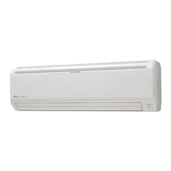
SPLIT TYPE
ROOM AIR CONDITIONER
WALL MOUNTED TYPE
Indoor unit
ASTA30LFC AOTR30LFT
CO NT E NT S
. . . . . . . . . . . . . . . . . . . . 1
. . . . . . . . . . . . . . . . . . . . . . . . 2
. . . . . . . . . . . . . . . . . . . 4
. . . . . . . . . . . . . . . . .
. . . . . . . . . . . . . . . . . . . . .
Outdoor unit
. . . . . 3
5
. . . . . . .
8
. . . . .
13
. . . . . . . . . . . . . . 15
. . . . . . . . . . . . 19
24
Advertisement
Table of Contents

Related Manuals for Fujitsu ASTA30LFC


Summary of Contents for Fujitsu ASTA30LFC
-
Page 1: Table Of Contents
ROOM AIR CONDITIONER WALL MOUNTED TYPE Indoor unit Outdoor unit ASTA30LFC AOTR30LFT CO NT E NT S ....1 SPECIFICATIONS ......2 DIMENSIONS . -
Page 2: Specifications
SP EC IF IC A T I O NS ELECTRICAL DATA COOL & HEAT INVERTER TYPE ASTA30LFC INDOOR UNIT AOTR30LFT OUTDOOR UNIT 8.00 kW COOLING CAPACITY 9.00 kW HEATING CAPACITY POWER SOURCE 240 V FREQUENCY 50 Hz COOLING 10.9 A... - Page 3 O U TLIN E A ND D IMENSI O NS (unit : mm) INDOOR UNIT OUTDOOR UNIT Air Flow 2009.09.28...
-
Page 4: Refrigerant System Diagram
RE F R I GE R A N T SYS T EM D IA GR A M Heat exchanger ( INDOOR ) 3-Way valve (Large) 3-Way valve Muffler (Small) Pressure Strainer switch Expansion valve 4-Way valve Heat exchanger Strainer ( OUTDOOR ) Cooling Heating Refrigerant pipe diameter... -
Page 5: Circuit Diagram
C I RCUI T D IA GR AM I NDOOR UNIT OUTDOOR UNIT CONTROLLER PCB ASSY ( MAIN PCB ) TEST HIGH PRESSURE SWITCH CN90 1 2 3 4 5 CN13 CONTROLLER PCB ASSY EX. OUT BLUE BROWN CN16 THERMISTOR ( COMPRESSOR TEMP. ) ( MAIN PCB ) YELLOW ( OPTION ) -
Page 6: Indoor Pcb Circuit Diagram
I NDO OR PC B CIRCU IT DI AGRAM CONTROL UNIT : EZ-009HHSE OUTDOOR UNIT TERMINAL THERMAL FUSE 102 SERIAL EARTH TERMINAL EARTH 22007 22007 22007 WIRED REMOTE CONTROL INDICATOR PCB CONTROLLER PCB ASSEMBLY ( OPTION ) ASSEMBLY K08CX-0900HSE-C1 K05CY-0500HSE-D0 CN6-1 CN6-2 WHITE... - Page 7 INDOOR UNIT CONTROLLER PCB ASSEMBLY K08CX-0900HSE-C1 340V MY064 0.01 <ECQE> D12 D2F20U D1FL20U R79, R81 - R84 D10 D1FL20U I C 2 6 10k <1/10W> x 5 G K - L V 3 0 1 1 E 4 T1-12 FSL 250V 3.15A ( EM ) 100/ 100k 420V...
- Page 8 INDOOR UNIT INDICATOR PCB ASSEMBLY K05CY-0500HSE-D0 CN201 07 JB20 / PAP 1061 L=230 D201 SLR-325VC D202 SLR-325MC GREEN C201 ORANGE <F> D203 SLR-325DC I C201 R201 GP1UM261RKVF <1/4W> + C202 2009.09.10...
-
Page 9: Outdoor Pcb Circuit Diagram
OUTDOOR PCB CIRCUIT DIAGRAM I VERTER ASSEMBLY EZ-0093HUE EMI FILTER ZCAT2132-1130 UL1015 AWG14 WHITE POWER SOURCE EMI FILTER UL1015 UL1015 AC230V AWG14 AWG14 ZCAT2132-1130 BLACK BLACK 50Hz UL3271 TLC 25A - 250V, B AWG20 TM101 UL1015 AWG14 ORANGE ( 250V 25A ) UL1015 POWER SUPPLY PCB ASSEMBLY AWG20... - Page 10 OUTDOOR UNIT CONTROLLER PCB ASSEMBLY CN200 1-1747052-2 K07BS-0900HUE-C1 G I C7.92-2P TP00351-31 x 2 FH200 FH201 1SS355 DC VOLT I N R601 F201 1.0k R603 FSL 250V 3.15A ( EM ) I C5 <1/10W> 150k 2200p 220/ CT600 7818 <2W> <E>...
- Page 11 OUTDOOR UNIT TRANSISTOR PCB ASSEMBLY ( I P M PCB ) K07BT-0900HUE-TR0 TM101 ORANGE C161 <X7R> BLACK TM102 BROWN D100 LL25XB60 CN303 1971032-5 WHITE I C70-2 BA2903F-E2 W306 WHITE I P M-GND TM301 YELLOW R284, R285, R302 0.04 <5W> x 3 POWER-G POWER-G TM302...
- Page 12 CT OUT OUTDOOR UNIT ORANGE GRAY POWER SUPPLY PCB ASSEMBLY BLACK PTC OUT ORANGE K05CW-0900HUE-FL0 L102 N200500K1D7C-02N BLACK ORANGE C101 VA100 C104 470V 0.033 0.022 C106 C100 C103 <YE> <TNR> <YE> C108 K101 VA101 C102 C105 DW12D1 <LE> <LE> <LE> <LE>...
- Page 13 OUTDOOR UNIT CAPACITOR PCB ASSEMBLY K05FB-0900HUE-P0 C200 - C203 660uF / 450WV x 4 WHITE YELLOW BLUE VIOLET POWER-G 2009.09.10...
-
Page 14: Error Contents
E R R OR C ON T EN T S Display Error Error Operation Timer LED 2 flash Serial signal (reverse) error, at operation start up 3 flash Serial signal (reverse) error, during oeration Serial signal error Normal 4 flash Serial signal (forward) error, at operation start up 5 flash Serial signal (forward) error, during operation... - Page 15 OUTDOOR UNIT ERROR Discharge temperature abnormal 0.5 second on / 0.5 second off IPM overcurrent protection 0.1 second on / 0.1 second off Thermistor abnormal CT abnormal 2.0 second on / 2.0 second off 0.1 second on / 2.0 second off Compressor location abnormal 5.0 second on / 5.0 second off Fan abnormal...
-
Page 16: Parts (Indoor Unit)
PARTS INDOOR UNIT Descriprion Part number Front Panel Total Assy 9315335012 Front Panel 9314991011 Intake Grille Assy 9315336019 Air Filter 9315014016 Clamper Grille 9306755010 Receiver Window 9315010018 Air Clean Filter Assy 9315212018 Remote 9315027139 Remote Holder 9305642045 2009.09.07... - Page 17 INDOOR UNIT Ref Descriprion Part number Crossflow Fan Assy 9315024015 Bearing C Assy 9306628017 Evaporator Total Assy 9315338020 Distributor Assy 9316988002 Water Seal 9315251015 Evaporater Holder R 9314994012 Evaporater Holder L 9314995019 Rear Bracket 9315022011 Filter Guide 9315013019 Filter Guard 9315411013 Connection Pipe Assy 9315355010...
- Page 18 INDOOR UNIT Descriprion Part number Descriprion Part number Casing Assy 9315331045 Louver U 9315000019 Casing Cover B 9315016010 Louver Z 9315001016 Casing Cover L 9315017017 Diffuser U 9315002013 Casing Cover R 9315018014 Diffuser Z 9315003010 Casing Cover F 9315019011 Spring C 9314142017 Drain Cap 9367677009...
- Page 19 INDOOR UNIT Ref Descriprion Part number Controller PCB with room thermistor 9708065137 Control Box 9314996016 Control Cover 9314997013 Motor Case 9314998010 Terminal Earth 9315028013 DC Brushless Motor 9602784004 Motor, Step 9900384029 Motor, Step 9900384036 Motor, Step 9900139063 Gear A 9309994003 Terminal 9900447014 Indicator PCB Assy...
-
Page 20: Parts (Outdoor Unit)
PART S OUTDOOR UNIT Ref. Description Part number Top Panel Sub Assy 9374417032 Front Panel Sub Assy 9374414079 Service Panel Sub Assy 9374415052 Emblem Rear 9351355005 Right Panel Sub Assy 9374416127 Valve Cover 9374174010 Protective Net 9375381011 2009.10.09... - Page 21 OUTDOOR UNIT Ref. Description Part number Base Assy 9374166138 Separate Wall Sub Assy 9374413188 Condenser A Assy 9374433056 Motor Bracket Sub Assy 9374418114 Fan Motor 9602843015 Propeller Fan Assy 9366378020 Valve Plate 9374099030 Compressor Cover A 9378851177 Compressor Cover B 9378851010 Compressor Cover C 9378851023...
- Page 22 OUTDOOR UNIT Ref. Description Part number Strainer Assy 9372524015 3-Way Valve Sub Assy 9377958013 3-Way Valve Assy 9377959010 Check Joint Assy 9372802038 Compressor Sub Assy 9379545006 Accumulator 9385005006 Accumulator Support Assy 9355351003 4-Way Valve 9900164010 Solenoid 9970055034 Pressure Switch 9900186012 Inlet Pipe (Cond) A Assy 9373461067 Outlet Pipe (Cond) A Assy...
- Page 23 OUTDOOR UNIT Connector : Yellow Connector : White Connector : Blue Connector : Red Ref. Description Part number PCB Case Assy 9375316020 Inverter Case 9375314019 ACTPM 9703457012 Thermistor 9704265012 Controller PCB Assy 9707667141 Power Supply PCB Assy 9707128208 Capacitor PCB Assy 9707257045 Transistor PCB Assy 9707669060...
-
Page 24: Accessories
A C CE SSO RI ES Name and Shape Part number Wall hook bracket 9315023018 Remote control 9315027139 Remote control holder 9305642045 Battery (penlight) 0600185534 Cloth tape 9310519004 Tapping screw (big) 0700076046 Tapping screw (small) 0700019036 Air cleaning filter 9312153060 9311925071 Air cleaning filter frame... - Page 25 0909G3665...