Table of Contents
Advertisement
Quick Links
Advertisement
Table of Contents
Troubleshooting

Related Manuals for Kohler PowerWAVE 8000DPA ST


Summary of Contents for Kohler PowerWAVE 8000DPA ST
- Page 1 User Manual...
- Page 2 TS_616_08 PW8000DPA ST (S2) UK User Manual 21/4/22...
- Page 3 All product, product specifications and data are subject to change without notice to improve reliability, function, design or otherwise. Kohler Uninterruptible Power Ltd. has taken every precaution to produce an accurate, complete and easy to understand specification document and will assume no responsibility nor liability for direct, indirect or accidental personal or material damage due to any misinterpretation of, or accidental errors, in this manual.
- Page 4 TS_616_08 PW8000DPA ST (S2) UK User Manual 21/4/22...
-
Page 5: Table Of Contents
1.3 Declaration of Safety conformity and CE marking General Description 2.1 General introduction 2.1.1 Reliability and quality standards 2.2 PowerWAVE 8000DPA ST (S2) DPA system 2.2.1 UPS cabinet model range 2.2.2 Advanced design features 2.2.3 System expansion using parallel cabinets 2.3 Functional description of operation... - Page 6 Installation 4.1 Introduction 4.2 Taking receipt of the UPS 4.2.1 Reporting transportation damage 4.2.2 Local transportation 4.2.3 Storage 4.3 Unpacking 4.3.1 Removing the standard UPS packaging (cardboard container) 4.3.2 Removing the alternative wooden crate packaging 4.3.3 Batteries 4.4 Power cabling 4.4.1 Safety notes 4.4.2 Power connections 4.4.3 Connecting the power cables (single-feed input)
- Page 7 8.2.3 WAVEMON UPS monitoring and control software 8.2.4 PowerREPORTER™ management software Specification 9.1 Mechanical characteristics – UPS Cabinet 9.2 UPS Module characteristics 9.3 Battery Data 9.4 Standards 9.5 Communication Options 9.6 Multi-cabinet configuration TS_616_08 PW8000DPA ST (S2) UK User Manual 21/4/22...
- Page 8 TS_616_08 PW8000DPA ST (S2) UK User Manual 21/4/22...
-
Page 9: Safety
UPS or peripheral equipment. CAUTION: The PowerWAVE 8000DPA ST is a Class A UPS product (according to EN 62040-3). In a domestic environment the UPS may cause radio interference. In such an environment the user may be required to undertake additional measures. -
Page 10: Declaration Of Safety Conformity And Ce Marking
Declaration of Safety conformity and CE marking The PowerWAVE 8000DPA ST UPS system is designed and manufactured in accordance with Quality Management Systems standard EN ISO 9001. The CE marking indicates conformity to the EEC Directive by the application of the following standards in accordance with the specifications of the harmonized standards: •... -
Page 11: General Description
2.1.1 Reliability and quality standards Using a unique modular construction, the PowerWAVE 8000DPA ST (S2) represents a completely new generation of medium power, 3 phase UPS-Systems, incorporating the latest technological developments in power engineering. High reliability, upgrade ability, low operating costs and excellent electrical performance are only some of the highlights of this innovative UPS solution. -
Page 12: Advanced Design Features
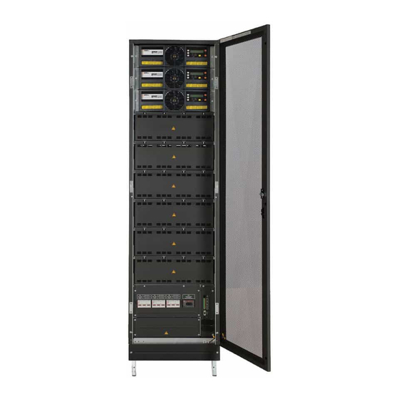
2: General Description The PowerWAVE 8000DPA ST (S2) is a truly flexible, modular UPS system designed around 10 kW or 20 kW UPS power modules. Up to ten UPS modules can be installed in a range of purpose-designed, free-standing cabinets, as shown in Figure 2.1. -
Page 13: System Expansion Using Parallel Cabinets
UPS system can be expanded to meet the growing demand without compromising the existing load. This requirement is well met with the ‘hot swappable’ nature of the PowerWAVE 8000DPA ST (S2) UPS power modules just described, which allows additional module(s) to be inserted into a vacant slot in an existing cabinet when needed;... - Page 14 2: General Description To J D5 i n UPSCABIN ET 3 Parallel Adapter Board Parallel Adapter Board Par al l elCont r olL ogic Par al l elCont r olL ogic UPS M odule 05 UPS M odule 10 Par al l elCont r olL ogic Par al l elCont r olL ogic UPS M odule 04 UPS M odule 09...
-
Page 15: Functional Description Of Operation
2: General Description Functional description of operation This section describes: • A block-diagram level explanation of the UPS module internal operation (see paragraph 2.3.1). • The various operational states of the UPS module (see paragraph 2.3.2). • UPS system-level operation – ‘ON-LINE’ versus ‘OFF-LINE’ UPS system operation (see paragraph 2.3.3). 2.3.1 UPS Power module internal operation STATIC... -
Page 16: Ups Module Operational States
2: General Description In a parallel-module installation (i.e. where two or more UPS modules fitted to the frame) the inverter control logic also ensures balanced load sharing between the on-line modules together with inter-module frequency synchronisation. Static switch The static switch provides a means of connecting the UPS AC output directly to the unregulated bypass mains supply. Working in conjunction with the inverter and output relay, the static switch control logic is able to transfer the UPS AC output (load) between the inverter and bypass supply without a break in the load supply. - Page 17 2: General Description UPS ON-BATTERY mode STATIC SWITCH Bypass Mains AC/DC (PFC) DC BOOST DC/AC CONVERTER CONVERTER INVERTER UPS AC Input Output Mains Input Output Relay Relay Automatic Batt. Switch BATTERY BATT. CHARGER UPS MODULE Figure 2.5 UPS ON-BATTERY The UPS automatically changes to the ON-BATTERY mode if the mains input supply fails during normal operation: •...
-
Page 18: Ups System Operation
2: General Description UPS ON MAINTENANCE BYPASS MAINTENANCE BYPASS STATIC SWITCH Bypass Mains AC/DC (PFC) DC BOOST DC/AC CONVERTER CONVERTER INVERTER UPS AC Input Output Mains Input Output Relay Relay Automatic Batt. Switch BATTERY BATT. CHARGER UPS MODULE Figure 2.7 UPS ON MAINTENANCE BYPASS Although the maintenance bypass switch is not fitted within the UPS module, the maintenance bypass mode of operation is shown here for completeness. - Page 19 2: General Description Bypass supply and fault handling If the UPS experiences an internal fault during ON-LINE operation, the inverter is turned off and the static switch transfers the load to the bypass supply automatically and without interruption provided the inverter and bypass supplies are synchronised (Figure 2.6).
-
Page 20: Module Component Identification
2: General Description Module component identification Module Control Panel UPS Module 2 (see page 21) UPS Module 1 Batteries Maintenance Bypass Switch (IA1) Module 2 Battery Isolator (F4-2) Module 1 Battery Isolator (F4-1) UPS Interface Connections (see page 17) Power Connections (see page 51) Figure 2.8 ST-40 Cabinet front view TS_616_08 PW8000DPA ST (S2) User Manual 21/4/22... - Page 21 2: General Description Module Control Panel UPS Module 3 (see page 21) UPS Module 2 UPS Module 1 Batteries Maintenance Bypass Switch (IA1) Module 3 Battery Isolator (F4-3) Module 2 Battery Isolator (F4-2) Module 1 Battery Isolator (F4-1) UPS Interface Connections (see page 17) Power Connections (see page 51)
- Page 22 2: General Description Module Control Panel UPS Module 4 (see page 21) UPS Module 3 UPS Module 2 Maintenance Bypass Switch (IA1) Module 4 Battery Isolator (F4-4) UPS Module 1 Module 3 Battery Isolator (F4-3) Module 2 Battery Isolator (F4-2) Module 1 Battery Isolator (F4-1) UPS Interface Connections (see page 17)
- Page 23 2: General Description Module Control Panel UPS Module 6 (see page 21) UPS Module 5 UPS Module 4 UPS Module 3 UPS Module 2 UPS Module 1 Maintenance Bypass Switch (IA1) Module 6 Battery Isolator (F4-6) Module 5 Battery Isolator (F4-5) Module 4 Battery Isolator (F4-4) Module 3 Battery Isolator (F4-3) UPS Interface Connections...
- Page 24 2: General Description Module Control Panel Module 10 Battery (see page 21) Isolator (F4-10) UPS Module 10 Module 9 Battery UPS Module 9 Isolator (F4-9) Module 8 Battery UPS Module 8 Isolator (F4-8) Module 7 Battery UPS Module 7 Isolator (F4-7) Module 6 Battery UPS Module 6 Isolator (F4-6)
-
Page 25: Powerwave 8000Dpa St (S2) Communications
2: General Description PowerWAVE 8000DPA ST (S2) Communications 2.5.1 Standalone cabinet communication System control panel Communications Interface Module UPS Power Board (CIB) control blocks panel System Battery Cont. Panel Input/output Dry-port Supplies Volt-free UPS Control system Outputs contacts for Power... -
Page 26: Parallel Cabinet Communication
2: General Description 2.5.2 Parallel cabinet communication System control panel Module Communications UPS Power Interface Board (CIB) control blocks panel System Battery Cont. Panel Input/output Dry-port Supplies Volt-free UPS Control system Outputs contacts for Power (data collection) remote alarms Switches Dry-port panel or BMS UPS Module 1... -
Page 27: Ups Interface Boards
2: General Description Figure 2.14 illustrates the UPS module communication facilities for a parallel cabinet PowerWAVE 8000DPA ST (S2) installation (two cabinets are shown). Module parallel control This diagram shows that in a parallel cabinet system the UPS modules within each cabinet communicate with each other via the cabinet’s internal parallel bus in exactly the same manner as described for a standalone cabinet system. - Page 28 2: General Description ST200 Cabinet ST40-120 Cabinet Customer Interface Board SLOT 1 Slot for optional Modem/Ethernet card ONLY. SLOT 2 Slot for optional SNMP card ONLY. RJ45 Port: (Not used) Customer output dry ports (Phoenix terminal block): Up to 5 output dry contacts used for signalling of the status of the UPS system (e.g.
-
Page 29: Module Control Panel
2: General Description Module control panel LCD Power management display Operator Module ON/OFF menu buttons buttons (x2) Mimic LED indicators Alarm LED/Reset Figure 2.16 LCD Control panel 2.6.1 Module mimic LED indicators The module mimic LED colours change between GREEN, RED and OFF to LINE 2 BYPASS indicate the operational status of key UPS stages, and thereby serve to... -
Page 30: Operator Buttons
2: General Description LED Indication summary INDICATOR STATUS INTERPRETATION LINE 1 GREEN Input mains supply is available and within acceptable parameters Input mains supply is unavailable or not within acceptable parameters – this is the normal display during an input mains power failure LINE 2 GREEN Bypass mains supply is available and within acceptable parameters... -
Page 31: Lcd Power Management Display
2: General Description 2.6.3 LCD Power management display Working in conjunction with the UP, DOWN and ENTER buttons, the LCD screen presents a range of selectable menus which allows the user to operate the UPS and monitor its performance – the menu tree is shown in Figure 2.18. Status screens During normal operation the LCD displays a UPS status screen similar to those shown below. - Page 32 2: General Description 01 dd‐mm‐yy hh:mm:ss BATT. RUN TIME (MIN) TOP LEVEL MENU [EVENT 01 DESCRIPTION] 00h 00m 02 dd‐mm‐yy hh:mm:ss OUTPUT FREQUENCY (HZ) EVENT LOG [EVENT 02 DESCRIPTION] 50.00 BYPASS FREQUENCY (HZ) MEASUREMENTS 50.00 BATTERY VOLTAGE (V) COMMANDS LOAD TO INVERTER +0.0 ‐ 0.0 BATT. CHARGE CUR. (A) UPS DATA LOAD TO BYPASS +0.0 ‐ 0.0 DISCHARGE CURRENT (A) SET‐UP USER PERFORM BATT. TEST 00.00 RECTIFIER VOLTAGE (V) SET‐UP SERVICE PERFORM DEEP BATT. TEST 000 000 000 BYPASS VOLTAGE (V) ABORT BATT. TEST 000 000 000 OUTPUT VOLTAGE (V) PERF. ALARM TEST 000 000 000 OUTPUT CURRENT (A)
-
Page 33: Optional System Control Panel
2: General Description Optional system control panel The system control panel is an optional component which is fitted to one UPS cabinet, usually the ‘master’ UPS, in a parallel cabinet system. It contains a microprocessor-based TFT touch- screen display which enables the operator to monitor the status of the overall UPS system as well as each individual UPS module. -
Page 34: Display Header Bar
2: General Description 2.7.1 Display header bar A navigation and status bar is displayed in the header area of every screen. Home Accesses the HOME screen. Mimic diagram Accesses the MIMIC diagram screen. Warning The warning symbol is only visible in the presence of a monitored alarm or fault event. Touching this icon will silence the audible alarm and open the EVENTS screen. -
Page 35: Mimic Diagram - System Level
2: General Description 2.7.2 Mimic diagram – system level The system level mimic diagram is the default screen. It shows the power flow through the UPS system and indicates its operational status – in either a single cabinet or multi-cabinet configuration. The operational status of each block is identified by its line colour, as shown below in Figure 2.22, with the green connecting lines indicating the power flow in the system. -
Page 36: Module Selection Screen
2: General Description 2.7.3 Module selection screen The module selection screen is accessed by pressing the MODULE SELECTION icon on the display header bar (item F in Figure 2.21). On opening, the screen displays an icon for every UPS module connected to the system (in all cabinets) and indicates their operating status through the colour-coding shown in Figure 2.23. - Page 37 2: General Description Module / System operational status mimic When a UPS ‘module level’ screen is accessed it’s display is similar to the default ‘system-level’ screen, except that the mimic display and metering refers specifically to the selected UPS module. Module / System ON-LINE This is the normal mimic indications for a (standard) ON-LINE UPS.
-
Page 38: Home Screen
2: General Description 2.7.4 Home screen The home screen, which is accessed by pressing the HOME icon on the display header bar on any screen (item A in Figure 2.21), contains six icons that provide access to various control and set-up function screen. Events Displays a list of recently occurred events with date, time, event name, description and sequential ID number. - Page 39 2: General Description Commands Available commands *Load to inverter *Load to bypass *User password protected UPS Data UPS Data Serial Number Manufacturing Firmware Version Hardware Version Display Version User UPS Settings Language Date Time Battery Test Repeat Test Generator Operation Service For the use of trained maintenance personnel only.
-
Page 40: Installation Planning
If the UPS is located in bayed enclosures, partition walls must be installed. e) The minimum cabinet clearances described below must be provided. 3.2.2 Installation The PowerWAVE 8000DPA ST (S2) is designed as a modular system contained in a range of UPS cabinets as illustrated in the table below. ST-40 ST-60... -
Page 41: Clearances
Kohler Uninterruptible Power Ltd can provide a range of suitable battery cabinets if required An external battery enclosure should be located as close as possible to the UPS cabinet(s) to reduce the volts drop on the DC cables when the batteries are in use –... - Page 42 3: Installation Planning PW8000 S2 (ST200) C3 FRONT + REAR PW8000 S2 ACCESS (ST200) REAR FANS FRONT + REAR ACCESS REAR FANS Min. Clearance 1000 mm 600 mm 300 mm 0 mm 230 mm C2 600 mm 115 deg. *400 mm = Battery Breaker Figure 3.2 ST200 Clearance recommendations ST-200 clearances notes...
-
Page 43: Electrical And Cabling Planning
Key Point: When planning a UPS installation that incorporates external batteries it is important that the battery enclosure installation requirements (access clearance, ventilation requirements, weight etc.) are accounted for in the planning process – if a non-Kohler Uninterruptible Power Ltd battery cabinet is to be used, these details must be obtained from the battery cabinet supplier. -
Page 44: Cable And Fuse Sizing
3: Installation Planning 3.3.2 Cable and fuse sizing Key Point: All external fuses, isolators and power cables must be rated and installed in accordance with the prescribed IEC standards or local regulation – e.g. BS7671. Input/bypass mains supply cables The UPS cabinet can be wired for a ‘single feed’ or ‘dual feed’... - Page 45 External batteries PW8000DPA ST models ST-80, ST-120 and ST-200 do not have provision for internal batteries and therefore require the batteries to be installed in an external enclosure. A range of external battery enclosures is available from Kohler Uninterruptible Power Ltd When planning for an external battery installation please consider the following: •...
- Page 46 3: Installation Planning UPS CABINET IA-1 (MBP) Fuse D EARTH Cable D Sta c Switch Common Input Links Fuse A Cable A Input Mains Rect. Inv. Load DC/DC Conv Module 1 Fuse F F4-1 Sta c Switch EARTH Rect. Inv. DC/DC Conv Module 2 F4-2 Sta c ...
- Page 47 3: Installation Planning UPS CABINET IA-1 (MBP) Fuse D EARTH Cable D Sta c Switch Common Input Links Fuse A Cable A Input Mains Rect. Inv. Load DC/DC Conv Module 1 Fuse E F4-1 Sta c Switch EARTH Rect. Inv. Cable E Fuse E DC/DC ...
- Page 48 3: Installation Planning UPS CABINET IA-1 (MBP) Fuse D EARTH Fuse B Cable B Cable D Sta c Bypass Mains Switch Fuse A Cable A Input Mains Rect. Inv. Load DC/DC Conv Module 1 Fuse F F4-1 Sta c Switch EARTH Rect. Inv.
- Page 49 3: Installation Planning UPS CABINET IA-1 (MBP) Fuse D EARTH Fuse B Cable B Cable D Sta c Bypass Mains Switch Fuse A Cable A Input Mains Rect. Inv. Load DC/DC Conv Module 1 Fuse E F4-1 Sta c Switch EARTH Rect. Inv.
- Page 50 3: Installation Planning Key Point: All fuses, isolators and power cables must be rated and installed in accordance with the prescribed IEC standards or local regulations – e.g. BS7671. The table below provides physical details of the UPS power connections. 400V / 230V BATTERY UPS INPUT MAINS...
-
Page 51: Parallel Cabinet Cabling Recommendations
3: Installation Planning 3.3.3 Parallel cabinet cabling recommendations In order to achieve equal load sharing between the various UPS cabinets in a multi-cabinet installation, the input cables from the mains switchboard to each UPS cabinet should be of equal length. Similarly the UPS output cables to the output (load) distribution panel should be of approximate equal length. -
Page 52: External Maintenance Bypass
INPUT BYPASS OUTPUT dedicated) switch-panel. Kohler Uninterruptible Power Ltd can provide a range of external maintenance bypass solutions to suit all of its UPS systems. Cable A/B Note: When starting the UPS system we advise that the load is initially... -
Page 53: Battery Configuration
As stated above, the batteries will be installed and connected by a Kohler Uninterruptible Power Ltd approved commissioning engineer. However, where external batteries are required (ST80, ST-120, ST-200) the customer’s should be aware of the external battery cabling requirements as it is the customer’s responsibility to provide appropriate... -
Page 54: Installation
All installation procedures must be carried out in strict accordance with the instructions contained in this manual. Kohler Uninterruptible Power Ltd. will take no responsibility for any personal injury or material damage caused by the incorrect installation, cabling or operation of this product. -
Page 55: Local Transportation
4: Installation 4.2.2 Local transportation The UPS is delivered on a specially designed pallet that is easy to move using a forklift or a pallet jack. Please observe the following precautions when you transport the UPS equipment after it has been off-loaded. CAUTION: Local transportation: •... -
Page 56: Unpacking
4: Installation Unpacking Key Point: Remove all packaging materials carefully, causing as little damage as possible, and temporarily store them in case the UPS has to returned to the manufacturer for any reason prior to commissioning. 4.3.1 Removing the standard UPS packaging (cardboard container) THIS NEEDS THOUROUGH CHECKING The outer packaging of ST-40 and ST-80 models comprises a cardboard sleeve with a folded top cover, as shown in Figure 4.2. -
Page 57: Removing The Alternative Wooden Crate Packaging
Battery life depends very much on temperature and should ideally be stored and operated at a temperature of 20°C. WARNING: If the UPS is delivered without batteries, Kohler Uninterruptible Power Ltd. will not accept responsibility for any damage or malfunctioning caused to the UPS by the incorrect storage, installation or connection of batteries carried out by third parties. -
Page 58: Power Cabling
Before you connect the UPS power cables ensure that the fuses and cables are suitably rated in accordance with the prescribed IEC standards or local regulations – for example BS7671. Once the electrical installation is completed the UPS must be commissioned by an engineer authorised by Kohler Uninterruptible Power Ltd. before it is powered up and brought into use. - Page 59 4: Installation Single/dual input links ST-40 3L1 3L3 Single/dual input links ST-60 Single/dual input links ST-80 External Batt. Common battery links ST-120 External Batt. Common battery links PE (Protective Earth) Figure 4.6 ST-40, ST-60, ST-80, ST-120 Power terminal connections TS_616_08 PW8000DPA ST (S2) User Manual 21/4/22...
- Page 60 4: Installation External Battery (2N) Common Single/Dual battery feed input links links Protective earth (PE) Bypass Mains supply (Dual input feed only) External Battery 1 2 3 4 5 2L1 2L2 2L3 2N Single/Dual feed input links 1L1 1L2 1L3 1N 3N 3L1 3L2 3L3 1 2 3 4 5 UPS Output supply...
-
Page 61: Connecting The Power Cables (Single-Feed Input)
4: Installation 4.4.3 Connecting the power cables (single-feed input) Connect an earth cable from the input mains switchboard to the UPS protective earth terminal (PE). If an external battery cabinet is used, connect an earth cable between the battery cabinet and the UPS battery earth terminal (PE). -
Page 62: Connecting The Battery
4.4.6 Connecting the battery IMPORTANT NOTE The batteries must be installed and connected by an approved Kohler Uninterruptible Power Ltd. commissioning engineer. High voltage battery strings can be extremely dangerous and should not be installed by the customer’s installation team. -
Page 63: Remote Monitoring And Control Facilities
4: Installation Remote monitoring and control facilities 4.5.1 PW8000DPA ST communications interface Various optional remote monitoring and control facilities can be connected to the PW8000DPA ST communications interface located on the front of the UPS frame. These are described on page 17 with connection details contained in Chapter 8. -
Page 64: Operation
Operation Introduction The PowerWAVE 8000DPA ST UPS system must be commissioned by a fully trained engineer authorised by Kohler Uninterruptible Power Ltd. before it is put into use. The commissioning engineer will: • Check the UPS electrical and mechanical installation, and operating environment. - Page 65 5: Operation STATIC SWITCH Bypass Mains AC/DC (PFC) DC BOOST DC/AC RECTIFIER CONVERTER INVERTER UPS AC Input Output Mains Input Output Relay Relay Automatic Batt. Switch BATTERY BATT. CHARGER UPS MODULE MAINTENANCE BYPASS STATIC SWITCH Bypass Mains AC/DC (PFC) DC BOOST DC/AC CONVERTER CONVERTER...
-
Page 66: How To Start The Ups System From A Fully Powered-Down Condition
5: Operation How to start the UPS system from a fully powered-down condition IMPORTANT NOTE In the following procedures, all references to the ‘Maintenance Bypass Switch’ apply to the internal maintenance bypass switch (IA1) unless the system is connected to an external maintenance bypass facility. If an external maintenance bypass facility is installed all references to the ‘Maintenance Bypass Switch’... - Page 67 5: Operation Start the UPS modules Carry out steps 8 to 10 below on each UPS module. Close the fused battery isolator (F4-x) (also close the battery fuse in the LINE 2 BY PASS external battery cabinet where used). a) The LINE 1 LED is green. LOAD LINE 1 INVERTER...
-
Page 68: Operating In Eco (On Bypass) Mode
5: Operation Operating in ECO (on bypass) mode When the UPS system is operated in ECO (on bypass) mode the load is powered from the UPS bypass mains supply, via the static switch, under normal conditions and transfers to the inverter (on inverter mode) automatically if the bypass mains supply fails. -
Page 69: How To Transfer To On-Line (On Inverter) From Eco (On Bypass) Mode
5: Operation 5.3.3 How to transfer to on-line (on inverter) from ECO (on bypass) mode The UPS can be manually switched to on-line (on inverter) from the ECO (on bypass) mode using the module control panel load transfer menu. On the module control panel (of any UPS module) press the ENTER key once to access the menu system. Using the UP/DOWN keys, move the cursor so that it is adjacent to COMMANDS and then press the ENTER key. -
Page 70: How To Transfer The Load To The Maintenance Bypass
5: Operation How to transfer the load to the maintenance bypass It may be necessary to transfer the load to the maintenance bypass supply to perform certain UPS service or maintenance operations – for example, when replacing a module in non-redundant system. This procedure is usually carried out by a trained service engineer and is not part of the normal day-to-day management of the UPS system. - Page 71 5: Operation Transfer the load to maintenance bypass: Close the maintenance bypass switch (see the IMPORTANT NOTE above). On the module control panel(s), verify that: LINE 2 BY PASS a) The INVERTER LED is red. b) The BYPASS LED is green. LOAD The module control panel will display MANUAL BYP IS CLOSED.
-
Page 72: How To Shut Down The Complete Ups System
5: Operation How to shut down the complete UPS system The UPS system can be completely shut down if the load does not require power for an extended period of time. CAUTION: Before you carry out this procedure, warn the critical load user that power is about to be removed. If the UPS system is not already operating on maintenance bypass, transfer the load to the maintenance bypass and turn OFF the UPS module(s) as described in paragraph 5.4. -
Page 73: Maintenance
Preventative maintenance inspections form an integral part of all Extended Warranty Agreements (maintenance contracts) offered by Kohler Uninterruptible Power Ltd. For further details on Extended Warranty Agreements see the warranty information at the front of this manual. -
Page 74: Battery Testing
6: Maintenance Battery testing A battery test can be initiated from the module control panel and takes approximately 3 minutes to complete. The test procedure can be carried out irrespective of the operating mode (‘on inverter’ or ‘on bypass’) and whether or not the load is connected, should be performed only if there are no existing alarm conditions and the battery is initially fully charged. -
Page 75: Troubleshooting
Investigative action is necessary only if it is not possible to reset the alarm or if the alarm occurrence is repetitive, in which case you should seek advice or assistance from the Kohler Uninterruptible Power Ltd. Service Department. Module control panel The module control panel is described on page 21. -
Page 76: Troubleshooting Table
Contacting service Kohler Uninterruptible Power Ltd. has a service department dedicated to providing routine maintenance and emergency service cover for your UPS. If you have any queries regarding your UPS please contact us. Kohler Uninterruptible Power Ltd. -
Page 77: Options
Options Customer communications ST-40, ST-60, ST-80, ST120 Cabinet ST200 Cabinet Customer Interface Board SLOT 1 Slot for optional Modem/Ethernet card ONLY SLOT 2 Slot for optional SNMP card ONLY RJ45 Port: (Not used) Customer output dry ports Customer input dry ports LEDs Status LEDs (red/green) RS232 Smart port computer interface... -
Page 78: Customer Control Inputs (X1)
UPS system commissioning process. If you wish to activate this feature after the system has been commissioned please contact Kohler Uninterruptible Power Ltd. service department for advice. To fit an external remote shutdown facility: Use a screened cable with 1 pair (section of wires 0.5 mm... - Page 79 Key Point: The battery temperature features will only function with the battery temperature sensor supplied by Kohler Uninterruptible Power Ltd.. If you attempt to use any other type of sensor it could have a damaging effect on the UPS operation.
-
Page 80: Dry Port Outputs (X2)
8: Options 8.1.2 Dry port outputs (X2) Terminal Contact Signal Display Function Contacts X2/15 ALARM COMMON_ALARM Common X2/14 No Alarm Condition X2/13 Common Alarm (system) X2/12 MESSAGE LOAD_ON_MAINS Common X2/11 Load On Inverter X2/10 Load On Bypass (mains) X2/9 ALARM BATTERY_LOW Common X2/8... -
Page 81: Network Interface Card Slots
8: Options 8.1.4 Network interface card slots The communications interface board contains two card slots that can be used with a range of network interface cards to interface the UPS system with a building management system or computer network. A suitable network interface card can be chosen to enable the UPS to be monitored and interrogated by one of following protocols: •... -
Page 82: Ups Monitoring And Automated Control Software
Kohler Uninterruptible Power Ltd. considers it important to have a complete solution for its UPS systems and offers its customers a number of remote control and monitoring tools to provide optimum protection. -
Page 83: Powerreporter™ Management Software
The main features and benefits offered by PowerREPORTER are: • real time alarm or critical event email notification sent directly to Kohler Uninterruptible Power Ltd. service centre • acquisition of key performance data and productivity information to allow a better understanding of the UPS system performance and quickly troubleshoot downtime events •... - Page 84 8: Options UPS with Users Reporting software Batteries Site manager Server Email Battery Care Alarm Event Data System & monthly report Servers with Power REPORTER UPS Email software server Consultant specialists KUP 24Hr Help-desk Analyst Service co-ordinator UPS Service Engineer Figure 8.7 Remote monitoring communications chain TS_616_08 PW8000DPA ST (S2) User Manual 21/4/22...
-
Page 85: Specification
Specification Mechanical characteristics – UPS Cabinet ST-40 ST-60 ST-80 ST-120 ST-200 Maximum 2 module 3 modules 4 modules 6 modules 10 modules configuration (10 or 20KW) + (10 or 20KW) + (10 or 20KW) (10 or 20KW) (10 or 20KW) 80 x 7Ah batteries 240 x 7Ah batteries NO batteries... -
Page 86: Ups Module Characteristics
9: Specification UPS Module characteristics Mechanical 10 kVA UPS module 20 kVA UPS module Dimensions (WxHxD) 448 x 132 x 540 (3 HU) (with front mounting wings) 488 x 132 x 540 (3 HU) Weight UPS module 18.6 21.5 Colours Front: RAL 9005 Input characteristics Output rated power per module cosφ... -
Page 87: Battery Data
9: Specification Heat Dissipation With Non-linear Load 10 kVA UPS module 20 kVA UPS module Heat dissipation with 100% non-linear load. Per module 1100 (EIN 62040-1-1:2003 Heat dissipation with 100% non-linear load. Per module BTU/h 1887 3754 (EIN 62040-1-1:2003) Airflow (25° - 30°C) with non-linear load. m³/h Per module (EIN 62040-1-1:2003) Dissipation at no load... -
Page 88: Standards
For monitoring and integration in network management Multi-cabinet configuration The PowerWAVE 8000DPA ST may be paralleled to increase the power capacity up to 400kW in steps of 10 or 20kW. A maximum of 20 modules can be paralleled, into four UPS cabinets.