Advertisement
Table of Contents
- 1 Table of Contents
- 2 Product Product Introduction
- 3 Introduction
- 4 Overview
- 5 Working P Working Principle
- 6 Discharge Performance
- 7 Maintenance
- 8 Environment
- 9 Power Plant
- 10 Panel
- 11 Installation
- 12 Installation of Battery Modules
- 13 Maintenance
- 14 Annex 1
- 15 Annex 2
- 16 Annex 3
- Download this manual
Advertisement
Table of Contents

Related Manuals for Narada NPFC Series


Summary of Contents for Narada NPFC Series
- Page 1 LiFePO LiFePO Battery Module for Telecom Battery Module for Telecom NPFC series NPFC series Operation Manual Operation Manual Version: 8.1 Version: 8.1 NARADA POWER SO NARADA POWER SOURCE CO., LTD URCE CO., LTD...
-
Page 3: Table Of Contents
Table of Contents Table of Contents – – Part 1 Part 1 Safety & Warning Safety & Warning ..............................................1 1 – – Part 2 Part 2 Product Product Introduction ......................Introduction ......................2 2 – – Overview Overview .......................... 2 .......................... - Page 5 Part 1 Part 1 Safety & Warning Safety & Warning – – The NPFC series LiFePO The NPFC series LiFePO battery system installation, operation, maintenance should follow battery system installation, operation, maintenance should follow important recommendations in this manual:...
-
Page 7: Product Product Introduction
Product Introduction Product Introduction Part 2 Part 2 Product Introduction Product Introduction – – – – Overview Overview NPFC series NPFC series battery battery system system is is 48V 48V system system for for communications communications back-up back-up type... - Page 9 Battery Management System (BMS) Battery Management System (BMS) Smart BMS technology is adopted for battery modules of NPFC series to assure smart Smart BMS technology is adopted for battery modules of NPFC series to assure smart automatic management for batteries. Features of BMS automatic management for batteries.
- Page 11 Instruction of Battery Model for NPFC Series – – Electric Performance Electric Performance – – Table 2.1 Table 2.1 Battery Model & Electric Performance of NPFC Series Battery Model & Electric Performance of NPFC Series Rated Rated Rated Rated Charge...
- Page 13 Structure and Mechanical Performance Structure and Mechanical Performance – – Fig. 2.3 Fig. 2.3 Structural Drawing of NPFC Series Batteries (48NPFC10 as sample) Structural Drawing of NPFC Series Batteries (48NPFC10 as sample) – – Fig. 2.4 Fig. 2.4 ...
- Page 15 – – Part Part 2 2 Product Introduction Product Introduction 图 图 2.6 Appearance & Mechanical Drawing of 48NPFC20 2.6 Appearance & Mechanical Drawing of 48NPFC20 图 图 2.7 Appearance Appearance & & Mechanical Mechanical Drawing Drawing of of 48NPFC30 48NPFC30 图...
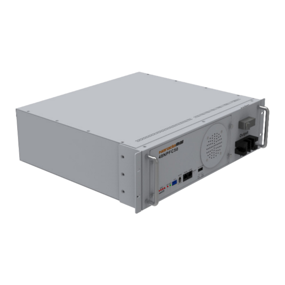
- Page 17 – – Part 2 Part 2 Product Product Introduction Introduction 图 图 2.10 2.10 Appearance Appearance & & Mechanical Mechanical Drawing Drawing of of 48NPFC60 48NPFC60 图 图 2.11 2.11 Appearance & & Mechanical Appearance Mechanical Drawing Drawing of of 48NPFC70 48NPFC70 图...
-
Page 19: Discharge Performance
Constant Current Discharge Curve of NPFC Series – – Charge Performance Charge Performance – – Fig. 3.2 Fig. 3.2 Charge Characteristic with Various Current Limitation of NPFC Series Charge Characteristic with Various Current Limitation of NPFC Series LiFePO LiFePO Battery Battery Module Module for... - Page 21 Characteristics – – Constant Current/Power Discharge Datasheet Constant Current/Power Discharge Datasheet – – Table 3.1 Table 3.1 Constant Current Discharge Datasheet of NPFC Series Constant Current Discharge Datasheet of NPFC Series Battery Battery Model Model 48NPFC10 48NPFC10 0.1C 0.1C...
- Page 23 – – Part Part 3 3 Technical Characteristics Technical Characteristics Battery Battery Model Model 48NPFC50 48NPFC50 Current Current 0.1C 0.1C 0.15C 0.15C 0.2C 0.2C 0.25C 0.25C 0.3C 0.3C 0.4C 0.4C 0.5C 0.5C 0.6C 0.6C 0.8C 0.8C End Volt. End Volt. 46.5V 46.5V 9.56...
- Page 25 – – Part 3 Part 3 Technical Technical Characteristi Characteristics cs – – Table 3.2 Table 3.2 Constant Power Discharge Datasheet of NPFC Series Constant Power Discharge Datasheet of NPFC Series Battery Battery Model Model 48NPFC10 48NPFC10 135W 135W...
- Page 27 – – Part Part 3 3 Technical Characteristics Technical Characteristics Battery Battery Model Model 48NPFC50 48NPFC50 Power Power 225W 225W 450W 450W 675W 675W 900W 900W 1125W 1125W 1350W 1350W 1575W 1575W End Volt. End Volt. 46.5V 46.5V 10.35 10.35 5.11 5.11...
-
Page 29: Maintenance
Parameter Settings of Power Plant Parameter Settings of Power Plant Lead-acid batteries can be replaced by lithium battery of NPFC series if power is matched. Lead-acid batteries can be replaced by lithium battery of NPFC series if power is matched. -
Page 31: Panel
Layout of Front Panel Layout of Front Panel – – Fig. 4.1 Fig. 4.1 Layout of Front Panel for NPFC Series Batteries Layout of Front Panel for NPFC Series Batteries – – Table 4.3 Table 4.3 Instruction for Layout of Front Panel Instruction for Layout of Front Panel... -
Page 33: Installation
Installation of Battery Modules 1) Installation and fixation 1) Installation and fixation Battery modules of NPFC series are applicable to installation in 19inches cabinets and Battery modules of NPFC series are applicable to installation in 19inches cabinets and wall-hanging. wall-hanging. -
Page 35: Maintenance
– – Part Part 4 4 Operation & Maintenance Operation & Maintenance Length of cable between battery module and power plant shall be less Length of cable between battery module and power plant shall be less than 2.0m. than 2.0m. - Page 37 – – Part 5 Part 5 Troubleshooting Troubleshooting & & Solutions Solutions Part 5 Part 5 Troubleshooting & Solutions Troubleshooting & Solutions – – – – Table 6.1 Table 6.1 Troubleshooting and Solutions Troubleshooting and Solutions Troubles Troubles Troubleshooting Troubleshooting Solutions...
-
Page 39: Annex 1
– – Annex Annex 1 1 Instructions for LED Flicker Instructions for LED Flicker Annex 1 Annex 1 Instructions for LED Flicker Instructions for LED Flicker – – – – Annex Table 1.1 Annex Table 1.1 SOC LED Indicators Description SOC LED Indicators Description ●... -
Page 41: Annex 2
– – Annex 2 Annex 2 Instructions Instructions for for Dialing Dialing of of ADD – – Annex 2 Annex 2 Instructions for Dialing of ADD Instructions for Dialing of ADD ADD is applicable to modules connected in parallel. ADD consists of four binary bits, and ADD is applicable to modules connected in parallel. -
Page 43: Annex 3
– – Annex Annex 3 3 Communication Protocol for RS232 and RS485 Communication Protocol for RS232 and RS485 – – Annex 3 Annex 3 Communication Protocol for RS232 and RS485 Communication Protocol for RS232 and RS485 There is one RS232 port in There is one RS232 port in front panel for up-link communication between batter module and front panel for up-link communication between batter module and upper computer, and one RS485 port in front panel for cascade communication for battery...