Table of Contents

Related Manuals for Narada NPFC Series


Summary of Contents for Narada NPFC Series
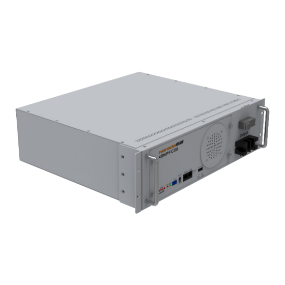
- Page 1 NPFC Series LiFePO Battery Module for Telecom LITHIUM IRON PHOSPHATE BATTERY NPFC Series (LiFePO Battery Module for Telecom) OPERATION MANUAL Version 9.0 NARADA POWER SOURCE CO., LTD Email: intl@narada.biz Website: en.naradapower.com...
-
Page 2: Table Of Contents
CONTENTS Notes Safety and Warning Product Introduction Product Features Main application Dimension Layout Working principle Technical Characteristic Discharge performance Charge performance Operation Three Parameter settings Operation condition Four Storage and Installation Storage Installation Five Maintenance General Troubleshooting and Solutions Annex1 Annex2 Annex3 Annex4... -
Page 3: Notes Safety And Warning
The NPFC series LiFePO battery system installation, operation, maintenance should follow important recommendations in this manual: NPFC series battery system is 48V system for communications back-up type LiFePO (lithium iron The equipment shall be installed by the professional trained staff. -
Page 4: Dimension
Annex 2. Note: Battery models listed in the datasheet are standard products. Narada can also supply ①Battery Model customized design in cell, BMS and dimensions for various application scenarios. The height of this battery is 138mm, is a litter higher than 132.5mm(3U). -
Page 5: Working Principle
Not recommend use handle to handing the battery. Battery Management System (BMS) Smart BMS technology is adopted for battery modules of NPFC series to assure smart automatic Side Wall-hanging The side mounting is used to wall-handing installation battery. -
Page 6: Discharge Performance
Battery modules can be controlled remotely Chapter Two/02 by staffs in control center. NPFC series are in line with the requirements of the development of modern communications technology. Discharge performance It is combined by technologies of power source and computer. Parameters and status of rectifiers and AC/DC distributions can be detected and controlled. -
Page 7: Operation
Three/03 Chapter Four/04 Parameter settings Storage Lead-acid batteries can be replaced by lithium battery of NPFC series if power is matched. Table 3-1 ■ Storage temperature range: 0°C to 40°C. is new parameter settings of power plant for lithium battery. - Page 8 Color for cable between ‘+’ and positive bar is suggested as RED, and cable between ‘-’ and Forbidden (Except for 48NPFC10, 48NPFC20, 48NPFC100-19) negative as BLACK. ■ The picture of paralleling connection for NPFC Series Batteries see Fig. 4-2. There is a tray under each battery to support the battery.
- Page 9 NPFC Series LiFePO Battery Module for Telecom Fig. 4-3 How to handle the empty RS485 port for NPFC Series Batteries 6.Discharge with dummy load ■ Dummy load cannot be larger maximum discharge current of each battery model according to the datasheet, and BLVD is larger than 43.2V.
-
Page 10: General
Different flash status of LED indicators represents corresponding running status or alarms. Detailed information is shown Annex 1. Note: The improvement of product and technology, and the possible of battery specification and appearance changes, Narada hold the right of final explanation! -
Page 11: Annex1
NPFC Series LiFePO Battery Module for Telecom Annex 1-Instructions for LED Flash Annex 2 – Instructions for ADD Dip Switch Annex Table 1.1 – SOC LED Indicators Description ADD Dip Switch is applicable to modules connected in parallel. ADD consists of four binary bits Annexed Table 2.1 –... -
Page 12: Annex3
■ Nominal Capacity: xxxx Ah 4,5,6,7,8 No connection The “Battery parameter settings” Subdirectory Non-manufacturers cannot enter 10 NPFC series LiFePO4 Battery System for Telecommunication Operation manual V1.0 The “Version Information” Subdirectory ■ “BMS version” Subdirectory ■ The “LCD version” Subdirectory ■... - Page 13 After-sale Services NARADA POWER SOURCE CO., LTD. Building A, No.822 Wen'er West Road, Hangzhou, Zhejiang, China Tel: +86-571-56975980 Fax: +86-571-56975955 Website: en.naradapower.com E -mail: intl@narada.biz NARADA ASIA PACIFIC PTE. LTD. Block 9 Khaki Bukit Road 1 #02-10 Eunos Technolink, Singapore 415938...