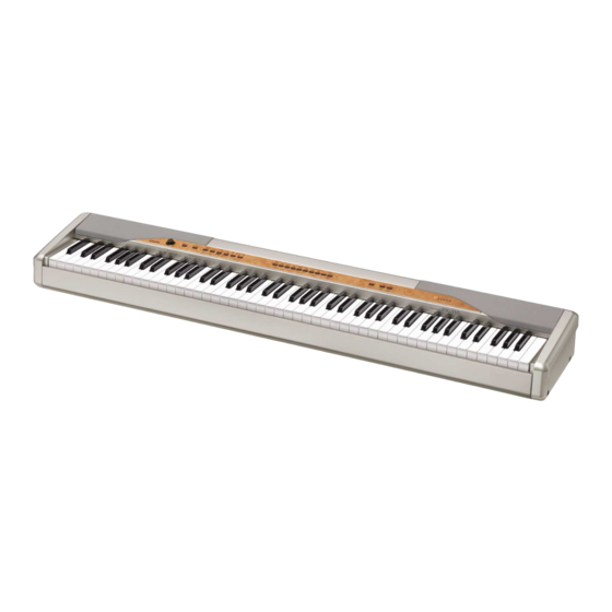
Casio PX-110 Service Manual
Hide thumbs
Also See for PX-110:
- User manual (32 pages) ,
- Safety precautions (2 pages) ,
- Function manual (65 pages)
Advertisement
Advertisement
Table of Contents

Related Manuals for Casio PX-110


Summary of Contents for Casio PX-110
- Page 1 PX-110 AUG. 2005 PX-110 ELECTRONIC KEYBOARD INDEX Ver.4 : Feb. 2009...
-
Page 2: Table Of Contents
CONTENTS Specifications ---------------------------------------------------------------------------------------------- 1 Block Diagram --------------------------------------------------------------------------------------------- 2 Circuit Description --------------------------------------------------------------------------------------- 3 Printed Circuit Board ------------------------------------------------------------------------------------ 5 Disassembly ------------------------------------------------------------------------------------------------ 7 Diagnostic Program ------------------------------------------------------------------------------------ 12 Schematic Diagrams ----------------------------------------------------------------------------------- 14 Exploded View ------------------------------------------------------------------------------------------- 21 Parts List --------------------------------------------------------------------------------------------------- 22... -
Page 3: Specifications
Auto Accompaniment: • Number of Rhythms: 20 • Tempo Range: 30 to 255 • Controllers: START/STOP, INTRO/ENDING, SYNCHRO/FILL-IN • Modes: Normal, CASIO CHORD, FINGERED, FULL RANGE CHORD • Accompaniment Volume: Adjustable Music Library: • Number of Tunes: 60 • Tune Volume: Adjustable •... -
Page 4: Block Diagram
BLOCK DIAGRAM MAIN PCB (M404-MDA1) Reset IC RESET MA0 ~ MA20 MA0 ~ MA16, 25 FLASH ROM (2Mbit) R1151N001C-TR LP62S2048A MD0 ~ MD7 EA0 ~ EA15,EA18 RAM (1Mbit) MA0 ~ MA22 ROM (128Mbit) CY62128DV30LL MR27V6402G19PTN ED12 ~ ED19 MD0 ~ MD15 uPD914AGM-JED 16.384MHz MA0 ~ MA3... -
Page 5: Circuit Description
CIRCUIT DESCRIPTION KEY MATRIX A0#1 C1#1 D1#1 A0#2 C1#2 D1#2 F1#1 G1#1 A1#1 F1#2 G1#2 A1#2 C2#1 D2#1 F2#1 G2#1 C2#2 D2#2 F2#2 G2#2 A2#1 C3#1 D3#1 A2#2 C3#2 D3#2 F3#1 G3#1 A3#1 F3#2 G3#2 A3#2 C4#1 D4#1 F4#1 G4#1 C4#2 D4#2 F4#2... - Page 6 BUTTON MATRIX RHYTHM START/ SONG TRACK (USER STOP MEMORY SONG) (DEMO) SYNCHRO/ INTRO/ METRONOME FUNCTION FILL-IN ENDING GRAND ELEC HARPSI- PIPE STRINGS PIANO 1 PIANO 1 CHORD ORGAN GRAND ELEC VIBRA- PERC ACOUSTIC PIANO 2 PIANO 2 PHONE ORGAN BASS CHORUS SPLIT REVERB...
-
Page 7: Printed Circuit Board
PRINTED CIRCUIT BOARDS MAIN PCB M404-MDA1 Top view Bottom view SUB PCB M404-PSA1 — 5 —... - Page 8 CONSOLE PCB M404-CNA1 Top view Bottom view CONSOLE PCB M404-CNB2 CONSOLE PCB M404-CNB4 CONSOLE PCB M404-CNB3 — 6 —...
-
Page 9: Disassembly
DISASSEMBLY 1. Remove 25 screws on the bottom. 2. Remove the lower panel and then 10 screws. 3. Position the main unit, so the main unit faces upward. 4. Remove 2 screws on the right side and 2 screws on the left side of the unit, and then remove side covers on both sides. - Page 10 6. Remove 4 connectors then the front panel. CN206 CN203 CN212 Removing the speaker 7. Remove 7 screws then the speaker cover. * Take the same procedure for the speaker on the right side. 8. Remove 4 screws then the speaker. * Take the same procedure for the speaker on the right side.
- Page 11 * Caution while assembling Place the cable in the groove. Removing the side case on the right. 14. Remove the side case on the right. Removing the side case on the left, the PCB (M403-JKA1) and the power switch. 15. Remove the side case on the left. 16.
- Page 12 18. Remove 2 screws and then the power switch. Removing the PCBs (M404-MDA1, M404-PSA1 and M403-JKB1). 19. Remove the connector and 2 screws then the PCB (M404-MDA1). 20. Remove 2 screws then the PCB (M404-PSA1). 21. Remove 4 screws and then the cover. 22.
- Page 13 Removing the key board. 24. Remove the keys from the hammers. 25. Remove the rubber keys. * One of the keys has the different length from others. Be careful while reassembling. 26. Remove the keys. 27. Remove 9 screws then the PCB (MCPZ-KYA1). 28.
-
Page 14: Diagnostic Program
DIAGNOSTIC PROGRAM Initial Setup 1. Connect an AC adaptor. 2. Connect a pedal cord. 3. "Main" volume: MAX. NOTE: If there is no pedal or MIDI cable, pedal or MIDI check can be skipped. How to start diagnostic program 1. Turn on the “POWER” button while the “SPLIT” and the “CHRUS” buttons are depressed. 2. - Page 15 5. Headphone check 1 Press “FUNCTION” button to perform the “Headphone check.” The confirmation chord C6 sounds and “PLAY” LED lights. 2 Connect the headphone to the LEFT jack. “REC” LED lights. 3 Remove the headphone from the jack. “PLAY” LED lights. 4 Connect the tuning meter to the RIGHT jack.
-
Page 16: Schematic Diagrams
SCHEMATIC DIAGRAMS MAIN PCB M404-MDA1 — 14 —... - Page 17 SUB PCB M404-PSA1 — 15 —...
- Page 18 CONSOLE PCB M404-CNA1 — 16 —...
- Page 19 CONSOLE PCB M404-CNB2 — 17 —...
- Page 20 CONSOLE PCB M404-CNB3 — 18 —...
- Page 21 CONSOLE PCB M404-CNB4 JACK PCB M403-JKB1 — 19 —...
- Page 22 JACK PCB M403-JKA1 — 20 —...
-
Page 23: Exploded View
EXPLODED VIEW 11 14 ×11 – 21 –... -
Page 24: Parts List
PARTS LIST PX-110 Notes: This parts list does not include the cosmetic parts, which parts are marked with item No. "R-X" in the exploded view. Contact our spare parts department if you need these parts for refurbish. 1. Prices and specifications are subject to change without prior notice. - Page 25 Price Item Parts Code Parts Name Specification R Remarks Code Main PCB 10208341 PCB ASSY-MAIN TK-RJM506205*001 10209154 BATTERY CR2032T6X 10133383 DIODE 02DZ2.7-Z(TPH3) 10098748 DIODE 02DZ5.6-Y(TPH3) 23902576 DIODE RB501V-40TE-17 F8,F9 10122975 FILTER EZASSB516BJ F1,F5,F6,F7,F10,F11 10122976 FILTER EZASTB63ABJ 30251862 FILTER NFM51R00P206 IC8,IC13 10211950 IC NJM2068M-D(TE1) 10175415 IC...
- Page 26 Price Item Parts Code Parts Name Specification R Remarks Code Console PCB 10208337 PCB ASSY/CNA1 TK-RJM506203*001 10159709 LSI UPD65881GK-1019ETA IC601 10096483 RESONATOR CSBFB1M00J58-R1 X601 10209564 LED KPTD-3216SURCK D602-611 10209018 TRANSISTOR KTA501U-GR-RTK/P Q601,602,607-608 10209027 TRANSISTOR KTC4076-Y-RTK/P Q610-612 SW601-610 10174669 SWITCH SKRKAEE010 10212709 HARNESS DS-8P-25-M404 CN602...
- Page 27 Price Item Parts Code Parts Name Specification R Remarks Code Case unit 10208334 COVER/SPEAKER L TK-RJM506070*001 10208329 COVER/SPEAKER R TK-RJM506069*001 10214565 SPEAKER C0612J52 10212713 HARNESS EH-2P-46-M404 10212715 HARNESS EH-2P-78-M404 10211772 KNOB/ROTARY RJM502503-011V01 10211866 KNOB/ROTARY RJM502503-013V02 PX-110DK 10203519 BUTTON/TACT/A RJM505580-002V01 10203525 BUTTON/TACT/A RJM505580-008V01 PX-110DK 10203520 BUTTON/TACT/A...
- Page 28 Ver.3: Dec. 2007 • Correction of the DIAGNOSTIC PROGRAM (P12) Ver.4: Feb. 2009 • Correction of the EXPLODED VIEW (P21) • Correction of the PARTS LIST (P25) CASIO COMPUTER CO.,LTD. Overseas Service Division 6-2, Hon-machi 1-Chome Shibuya-ku, Tokyo 151-8543, Japan...