Table of Contents
Advertisement
Available languages
Available languages
Quick Links
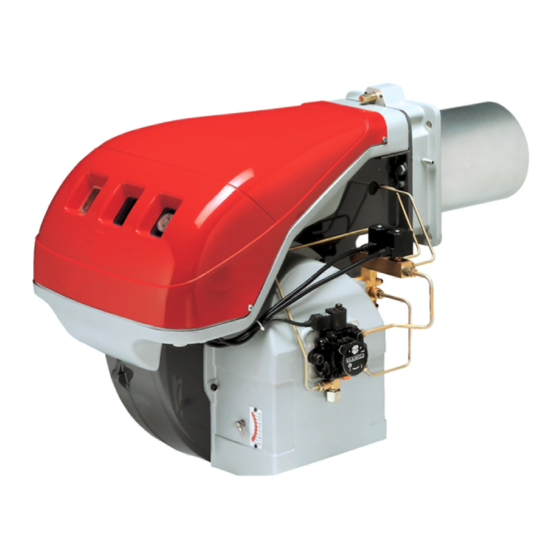
TECNO 70-L, 100-L & 130-L
Light oil burners
GB
Two-stage operation
Installation, use and maintenance instructions
Bruciatori di gasolio
I
Funzionamento bistadio
Istruzioni per installazione, uso e manutenzione
CODE - CODICE
143114200
143115200
143116200
MODEL - MODELLO
TECNO 70-L
TECNO 100-L
TECNO 130-L
2916089 (15) - 06/2021
Advertisement
Chapters
Table of Contents

Related Manuals for Baxi TECNO 70-L


Summary of Contents for Baxi TECNO 70-L
- Page 1 TECNO 70-L, 100-L & 130-L Light oil burners Two-stage operation Installation, use and maintenance instructions Bruciatori di gasolio Funzionamento bistadio Istruzioni per installazione, uso e manutenzione CODE - CODICE MODEL - MODELLO 143114200 TECNO 70-L 143115200 TECNO 100-L 143116200 TECNO 130-L...
-
Page 3: Table Of Contents
Contents Information and general instructions............................2 Information about the instruction manual ..............................2 Guarantee and responsibility ..................................3 Safety and prevention................................4 Introduction ........................................4 Personnel training ......................................4 Technical description of the burner ............................5 Technical data.......................................5 Electrical data........................................5 Burner description (Fig. 2).....................................7 Firing rates (Fig. -
Page 4: Information And General Instructions
Information and general instructions Information and general instructions Information about the instruction manual Introduction 1.1.2 Danger: live components The instruction manual supplied with the burner: This symbol indicates operations which, if not car- is an integral and essential part of the product and must not ried out correctly, lead to electric shocks with le- be separated from it;... -
Page 5: Guarantee And Responsibility
Information and general instructions Guarantee and responsibility The Manufacturer guarantees its new products from the installa- tion date, in accordance with the regulations in force and/or the sales contract. At the moment of the first start-up, check that the burner is integral and complete. Failure to observe the information given in this manual, operating negligence, incorrect installa- tion and the carrying out of non authorised modifi-... -
Page 6: Safety And Prevention
Safety and prevention Safety and prevention Introduction Personnel training The Manufacturer burners have been designed and built in com- The user is the person, body or company that has acquired the pliance with current regulations and directives, applying the machine and intends to use it for the specific purpose. He is re- known technical rules of safety and envisaging all the potential sponsible for the machine and for the training of the people work- danger situations. -
Page 7: Technical Description Of The Burner
Technical description of the burner Technical description of the burner Technical data MODEL TECNO 70-L TECNO 100-L TECNO 130-L TYPE 660 T1 661 T1 662 T1 OUTPUT 2nd stage 474 - 830 711 - 1186 948 - 1540 408 - 714... - Page 8 Technical description of the burner 3.2.1 Variants Power supply Length of Model Code electrical blast tube mm TECNO 70-L 143114200 660 T1 Three-phase TECNO 100-L 143115200 661 T1 Three-phase TECNO 130-L 143116200 662 T1 Three-phase 3.2.2 Max. dimensions (Fig. 1) - The maximum dimensions of the burner are given in (Fig.
-
Page 9: Burner Description (Fig. 2)
Motor trip: release by pressing the pushbutton on thermal cut- out 17)(Fig. 2). 3.3.1 Weight (Tab. A) - approximate measurements • The weight of the burner complete with its packaging is shown in table (Tab. A) TECNO 70-L 43,5 TECNO 100-L 46,5 TECNO 130-L 51,5 Tab. A... -
Page 10: Firing Rates (Fig. 3)
Technical description of the burner Firing rates (Fig. 3) The TECNO 70-L - 100 L - 130 L burners model can work in two ways: one-stage and two-stage. D3314 1st stage DELIVERY must be selected within area A of the ad- jacent diagrams. -
Page 11: Installation
Installation Installation Notes on safety for the installation After carefully cleaning all around the area where the burner will be installed, and arranging the correct lighting of the environment, proceed with the installation operations. All the installation, maintenance and disassembly The installation of the burner must be carried out operations must be carried out with the electricity by qualified personnel, as indicated in this manual... -
Page 12: Boiler Plate (Fig. 6)
Boiler plate (Fig. 6) Drill the combustion chamber locking plate as shown in (Fig. 6). The position of the threaded holes can be marked using the ther- mal screen supplied with the burner. TECNO 70-L M 12 TECNO 100-L M 12... -
Page 13: Choice Of Nozzles For 1St And 2Nd Stage
Example with the TECNO 70-L model: ratio 40 - 100% between the 1st and 2nd stage; Boiler output = 635 kW - efficiency 90 % ... -
Page 14: Nozzle Assembly
Installation Nozzle assembly At this stage of installation the burner is still disassembled from the blast tube; it is therefore possible to fit two nozzles with the box spanner 1)(Fig. 9) (16 mm), after having removed the plastic plugs 2) (Fig. 9), fitting the spanner through the central hole in the flame stability disk. -
Page 15: Combustion Head Setting
Turn screw 4) (Fig. 13) until the notch shown in diagram (Fig. 14) is level with the front surface of flange 5) (Fig. 13). Example: The TECNO 70-L Model with two 6.0 GPH nozzles and 12 bar pump pressure. Fig. 13 D462 Find the delivery of the two 6.0 GPH nozzles in Tab. -
Page 16: Electrical System
Electrical system Electrical system Notes on safety for the electrical wiring The electrical wiring must be carried out with the electrical supply disconnected. Electrical wiring must be carried out by qualified personnel and in compliance with the regulations currently in force in the country of destination. - Page 17 Electrical system 5.1.2 Electrical wiring factory-set 20078333 Fig. 16 Key to layout (Fig. 16) The burners leave the factory preset for 400V Motor contactor power supply. Flame sensor If 230V power supply is used, change the motor Switch: burner off - on WARNING connection from star to delta and change the set- Switch: 1st - 2nd stage operation...
-
Page 18: Calibration Of Thermal Relay
Fuses and cables cross-section (Fig. 17), see Tab. C. Key to layout (Fig. 17) 1st stage hourcounter Cross-section when not indicated: 1.5 mm 2nd stage hourcounter TECNO 70-L TECNO 100-L TECNO 130-L Manual burner stop switch Terminal strip 230 V... -
Page 19: Hydraulic System
This circuit is extremely useful whenever the burner pump does not succeed in self-priming because the tank dis- tance and/or height difference are higher than the values listed in the table. L (m) TECNO 70-L TECNO 100-L - 130 L Ø (mm) Ø (mm) + 4.0 + 3.0... -
Page 20: Hydraulic Connections (Fig. 20)
Now connect the other end of the hoses to the supplied nipples, using two wrenches, one to hold the nipple steady while using the other one to turn the rotary union on the hose. TECNO 70-L TECNO 100-L - TECNO 130-L PUMP SUNTEC AL 95 C PUMP SUNTEC AJ6 CC Fig. -
Page 21: Burner Calibration
– in rh direction (- sign) the opening is reduced; – in lh direction (+ sign) the opening increases. Example: TECNO 70-L - 1st stage nozzle 6.0 GPH: 2.3 notch (Fig. 23) aligned with index 1). When the adjustment is terminated lock the hex element 2) D699 (Fig. - Page 22 Burner calibration With shutter 4) retracted (Fig. 8 pag. 10) TECNO 70-L TECNO 100-L TECNO 130-L NOTE: kg/h mbar kg/h mbar kg/h mbar in order to facilitate adjustment of hex elements 2) and 4) (Fig. 24), use a 3 mm Allen key 5) (Fig. 24).
- Page 23 Burner calibration 7.2.1 Burner starting (Fig. 26) - (Fig. 27) 7.2.2 Steady state operation System equipped with one control device TR D3315 Once the starting cycle has come to an end, the command of the 2nd stage solenoid valve passes on to the control device TR that controls boiler temperature or pressure.
-
Page 24: Maintenance
Maintenance Maintenance Notes on safety for the maintenance Filters (Fig. 28) The periodic maintenance is essential for the good operation, Check the following filter boxes: safety, yield and duration of the burner. • on line 1) • in the pump 2) • at the nozzle 3), and clean or replace It allows you to reduce consumption and polluting emissions and as required. - Page 25 Maintenance Flame inspection window (Fig. 30) Fuel pump and/or couplings replacement (Fig. 32) Clean the glass whenever necessary. In conformity with figures (Fig. 32) D709 D1108 Fig. 32 Fig. 30 Flexible hoses Check to make sure that the flexible hoses are still in good con- dition and that they are not crushed or otherwise deformed.
-
Page 26: Burner Start-Up Cycle Diagnostics
Maintenance Burner start-up cycle diagnostics During start-up, indication is according to the following table: Colour code table Sequences Colour code Pre-purging Ignition phase Operation, flame ok Operating with weak flame signal Electrical supply lower than ~ 170V Lockout Extraneous light Key: Yellow Green... -
Page 27: Software Diagnostics
Maintenance Software diagnostics Reports burner life by means of an optical link with the PC, indi- Release the button for 1 second and then press again for over cating hours of operation, number and type of lock-outs, serial 3 seconds until the yellow light pulses again. number of control box etc. - Page 28 Maintenance SIGNAL FAULT PROBABLE CAUSE SUGGESTED REMEDY 7 led blinks Flame detachment 34 - Poorly adjusted head ......Adjust, see pag.
- Page 29 Indice Informazioni ed avvertenze generali ............................2 Informazioni sul manuale di istruzione ................................2 Garanzia e responsabilità .....................................3 Sicurezza e prevenzione................................4 Premessa ........................................4 Addestramento del personale ..................................4 Descrizione tecnica del bruciatore ............................5 Dati tecnici........................................5 Dati elettrici ........................................5 Descrizione bruciatore (Fig. 2) ..................................7 Campi di lavoro (Fig.
-
Page 30: Informazioni Ed Avvertenze Generali
Informazioni ed avvertenze generali Informazioni ed avvertenze generali Informazioni sul manuale di istruzione Introduzione 1.1.2 Pericolo componenti in tensione Il manuale di istruzione dato a corredo del bruciatore: Questo simbolo contraddistingue operazioni che, costituisce parte integrante ed essenziale del prodotto e non correttamente eseguite, comportano non va da esso separato;... -
Page 31: Garanzia E Responsabilità
Informazioni ed avvertenze generali Garanzia e responsabilità La Ditta Costruttrice garantisce i suoi prodotti nuovi dalla data dell’installazione secondo le normative vigenti e/o in accordo con il contratto di vendita. Verificare, all’atto della prima messa in fun- zione, che il bruciatore sia integro e completo. La mancata osservanza a quanto descritto in que- sto manuale, la negligenza operativa, una errata installazione e l’esecuzione di modifiche non au-... -
Page 32: Sicurezza E Prevenzione
Sicurezza e prevenzione Sicurezza e prevenzione Premessa Addestramento del personale I bruciatori sono stati progettati e costruiti in conformità alle nor- L’utente è la persona, o l’ente o la società, che ha acquistato la me e direttive vigenti, applicando le regole tecniche di sicurezza macchina e che intende usarla per gli usi concepiti allo scopo. -
Page 33: Descrizione Tecnica Del Bruciatore
Descrizione tecnica del bruciatore Descrizione tecnica del bruciatore Dati tecnici MODELLO TECNO 70-L TECNO 100-L TECNO 130-L TIPO 660 T1 661 T1 662 T1 POTENZA stadio 2° 474 - 830 711 - 1186 948 - 1540 408 - 714 612 - 1020... - Page 34 Descrizione tecnica del bruciatore 3.2.1 Versioni costruttive Alimentazione Lunghezza Modello Codice Tipo elettrica boccaglio mm TECNO 70-L 143114200 660 T1 Trifase TECNO 100-L 143115200 661 T1 Trifase TECNO 130-L 143116200 662 T1 Trifase 3.2.2 Ingombro (Fig. 1) - misure indicative L’ingombro del bruciatore è...
-
Page 35: Descrizione Bruciatore (Fig. 2)
Blocco motore: per sbloccare premere il pulsante del relè termi- co 17)(Fig. 2). 3.3.1 Peso (Tab. A) - misure indicative • Il peso del bruciatore completo di imballo è indicato in tabella (Tab. A). TECNO 70-L 43,5 TECNO 100-L 46,5 TECNO 130-L 51,5 Tab. A... -
Page 36: Campi Di Lavoro (Fig. 3)
Descrizione tecnica del bruciatore Campi di lavoro (Fig. 3) I bruciatori TECNO 70-L - 100 L - 130 L possono funzionare in D3314 due modi: monostadio e bistadio. La PORTATA del 1° stadio va scelta entro l’area A dei diagram- mi a lato. -
Page 37: Installazione
Installazione Installazione Note sulla sicurezza per l’installazione Dopo avere effettuato un’accurata pulizia tutt’intorno all’area destinata all’installazione del buciatore ed avere provveduto ad una cor- retta illuminazione dell’ambiente, procedere con le operazioni di installazione. Tutte le operazioni di installazione, manutenzione L’installazione del bruciatore deve essere effet- e smontaggio devono assolutamente essere ese- tuata da personale abilitato, secondo quanto ri- guite con rete elettrica staccata. -
Page 38: Piastra Caldaia (Fig. 6)
Piastra caldaia (Fig. 6) Forare la piastra di chiusura della camera di combustione come in (Fig. 6). La posizione dei fori filettati può essere tracciata utiliz- zando lo schermo termico a corredo del bruciatore. TECNO 70-L M 12 TECNO 100-L M 12... -
Page 39: Scelta Degli Ugelli Per Il 1° E 2° Stadio
10°C una portata superiore al 50% della portata totale, quando si desidera migliorare la combustione in 1° stadio. Esempio con TECNO 70-L Potenza caldaia = 635 kW - rendimento 90 % Potenza richiesta al bruciatore = 635 : 0,9... -
Page 40: Montaggio Degli Ugelli
Installazione Montaggio degli ugelli A questo punto dell’installazione il bruciatore è ancora separato dal boccaglio; è perciò possibile montare i due ugelli con la chia- ve a tubo 1) (Fig. 9) (da 16 mm), dopo aver tolto i tappi in plastica 2) (Fig. -
Page 41: Regolazione Testa Di Combustione
Ruotare la vite 4) (Fig. 13) fino a far collimare la tacca indicata dal diagramma (Fig. 14) con il piano anteriore della flangia 5) (Fig. 13). Esempio: TECNO 70-L con due ugelli da 6,0 GPH e pressione in pompa 12 Fig. 13 bar. D462 Trovare nella tabella (Tab. -
Page 42: Impianto Elettrico
Impianto elettrico Impianto elettrico Note sulla sicurezza per i collegamenti elettrici I collegamenti elettrici devono essere eseguiti in assenza di alimentazione elettrica. I collegamenti elettrici devono essere eseguiti secondo le norme vigenti nel paese di destinazione e da personale qualificato. - Page 43 Impianto elettrico 5.1.2 Impianto elettrico eseguito in fabbrica 20078333 Fig. 16 Legenda (Fig. 16) I bruciatori lasciano la fabbrica previsti per alimen- Contattore motore tazione elettrica 400V. Sensore fiamma Se l'alimentazione è 230V, cambiare il collega- Interruttore: bruciatore acceso-spento ATTENZIONE mento del motore (da stella a triangolo) e la tara- Interruttore: 1°...
-
Page 44: Taratura Del Relè Termico
Sezione cavi e fusibili (Fig. 17), vedi Tab. C. Legenda (Fig. 17) Contaore di 1° stadio Sezione quando non specificato: 1,5 mm Contaore di 2° stadio TECNO 70-L TECNO 100-L TECNO 130-L Interruttore elettrico per arresto manuale bruciatore Morsettiera 230 V... -
Page 45: Impianto Idraulico
Questo circuito è necessario quando la pom- pa del bruciatore non riesce ad autoalimentarsi perché la distanza e/o il dislivello della cisterna sono superiori ai valori ri- portati in tabella. L (m) TECNO 70-L TECNO 100-L - 130 L Ø (mm) Ø (mm) + 4,0... -
Page 46: Collegamenti Idraulici (Fig. 20)
TECNO 70-L TECNO 100-L - TECNO 130-L POMPA SUNTEC AL 95 C POMPA SUNTEC AJ6 CC Fig. -
Page 47: Regolazione Bruciatore
– verso destra (segno -) l’apertura diminuisce; – verso sinistra (segno +) l’apertura aumenta. Esempio: TECNO 70-L - Ugello 1° stadio 6,0 GPH: tacca 2,3 (Fig. 23) in corrispondenza con l’indice 1). A regolazione ultimata bloccare l’esagono 2) (Fig. 24) con la ghiera 1). - Page 48 Regolazione bruciatore Senza otturatore 4) (Fig. 8 pag. 10) TECNO 70-L TECNO 100-L TECNO 130-L NOTA: kg/h mbar kg/h mbar kg/h mbar per facilitare la regolazione degli esagoni 2) e 4) (Fig. 24), servirsi della chiave esagona da 3 mm 5) (Fig. 24).
- Page 49 Regolazione bruciatore 7.2.1 Avviamento bruciatore (Fig. 26) - (Fig. 27) 7.2.2 Funzionamento a regime D3315 Impianto dotato di un telecomando TR Terminato il ciclo di avviamento, il comando dell’elettrovalvola di 2° stadio passa al telecomando TR che controlla la pressione o la temperatura in caldaia.
-
Page 50: Manutenzione
Manutenzione Manutenzione Note sulla sicurezza per la manutenzione Filtri (Fig. 28) La manutenzione periodica è essenziale per il buon funziona- Controllare i cestelli filtranti: mento, la sicurezza, il rendimento e la durata del bruciatore. • di linea 1) • in pompa 2) • all’ugello 3), pulirli o sostituirli. Essa consente di ridurre i consumi, le emissioni inquinanti e di Se all’interno della pompa si notano ruggine o altre impurità, aspi- mantenere il prodotto affidabile nel tempo. - Page 51 Manutenzione Visore fiamma (Fig. 30) Eventuale sostituzione pompa e/o giunti (Fig. 32) Pulire il vetrino quando è necessario. Eseguire il montaggio rispettando le indicazioni delle figure (Fig. 32). D709 D1108 Fig. 32 Fig. 30 Tubi flessibili Controllare che il loro stato sia buono, che non siano stati calpe- stati o deformati.
-
Page 52: Diagnostica Programma Di Avviamento
Manutenzione Diagnostica programma di avviamento Durante il programma di avviamento, le indicazioni sono esplica- te nella seguente tabella: Tabella codice colore Sequenze Codice colore Preventilazione Fase di accensione Funzionamento con fiamma ok Funzionamento con segnale di fiamma debole Alimentazione elettrica inferiore a ~ 170V Blocco Luce estranea Legenda:... -
Page 53: Diagnostica Software
Manutenzione Diagnostica software Fornisce l’analisi della vita del bruciatore mediante collegamento di 3 secondi fino alla visualizzazione di un ulteriore lampeggio ottico a PC indicandone ore di funzionamento, numero e tipologie di colore giallo. di blocchi, numero di serie dell’apparecchiatura etc… Al rilascio del pulsante il led rosso lampeggerà... - Page 54 Manutenzione SEGNALE INCONVENIENTE CAUSA PROBABILE RIMEDIO CONSIGLIATO 7 lampeggi Stacco fiamma 34 - Testa mal regolata ......Regolarla, vedi pag.