Table of Contents
Advertisement
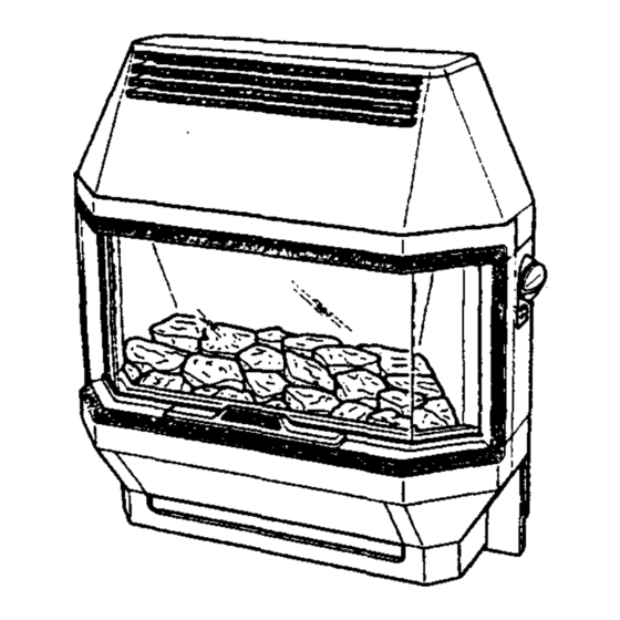
Baxi Arena Super
Baxi Baroque Super
Living Flame Effect Gas Fires
Natural Gas
Comp N° 235317 - Issue 8 - 11/99
Baxi Arena Super - G.C.N° 32 077 34
Baxi Baroque Super - G.C.N° 32 077 35
Supplied By www.heating spares.co Tel. 0161 620 6677
Installation and
Servicing Instructions
Please leave these instructions with the user
Advertisement
Table of Contents

Related Manuals for Baxi Arena Super


Summary of Contents for Baxi Arena Super
- Page 1 Living Flame Effect Gas Fires Natural Gas Comp N° 235317 - Issue 8 - 11/99 Installation and Servicing Instructions Baxi Arena Super - G.C.N° 32 077 34 Baxi Baroque Super - G.C.N° 32 077 35 Supplied By www.heating spares.co Tel. 0161 620 6677...
-
Page 2: Table Of Contents
Initial Preparation Fitting the Fire Electrical Connections Commissioning the Fire PAGE 10-12 Spillage Detection PAGE 13-14 Fitting the Outer Case Baxi Baroque Baxi Arena PAGE 15-19 Annual Servicing Cleaning the Pilot Assembly Cleaning the Burner/Injectors PAGE 20-27 Changing Components Glass Frame... -
Page 3: Introduction
INTRODUCTION - Page 3 Description The Baxi Baroque Super and Baxi Arena Super are living flame effect gas fires with a heat input of 5.57 kW (19,000 Btu/h) and an output of 3.40 kW (11,590 Btu/h) at its maximum setting. The fires are available for use with Gas Type G20 (Natural Gas) at 20mbar supply pressure. -
Page 4: Technical Data
TECHNICAL DATA - Page 4 Baxi Baroque Super Baxi Arena Super B.S. Codes of Practice STANDARD SCOPE B.S. 6891 Gas Installation B.S. 5871 Installation of gas fires, convectors and fire/back boilers. B.S. 5440: Part 1 Flues. B.S. 5440: Part 2 Air Supply Supplied By www.heating spares.co Tel. -
Page 5: Site Requirements
SITE REQUIREMENTS - Page 5 Fireplace Opening The installation requires a fireplace opening as illustrated. At the height of the flue spigot the opening shall be no less than 100mm (4in) deep, measured from the front face of the opening to the fireplace back brick. There must be a minimum of 412mm (16 in) between the base of the fireplace opening and the bottom of the flue spigot. - Page 6 Site Requirements - Page 6 Existing Chimneys A chimney which has previously been used to burn solid fuel MUST be swept before beginning the installation and any restrictions such as dampers or register plates must be removed. The chimney must be at least 3.10m (10ft) in height and also meet the following requirements: It must not be cracked.
-
Page 7: Installation
INSTALLATION - Page 7 Initial Preparation To unpack the fire, remove the packing piece complete with fitments and the pack containing the canopy and hearth assembly. Place to one side. Remove the plastic bag and remaining packing piece. Lift the fire from its carton. Fitting the Fire HEARTH MOUNTING Take the closure plate provided and hold centrally across the... - Page 8 INSTALLATION - Page 8 Wall Fixing Using the closure plate supplied as a template, hold it centrally across the fireplace opening with the bottom edge level with the base of the fireplace opening. Mark out the six hole positions. Remove the closure plate and drill the fixing holes using a 6mm drill to accept the wall plugs provided.
- Page 9 Electrical Connections - Page 9 Electricity is supplied to the fire unit via the plug-and-cable assembly provided with the appliance. WARNING THIS APPLIANCE MUST BE EARTHED. 3 core input cable for connection to the mains input must NOT be less than 0.5mm (16 x 0.2mm) PVC heat resistant to 70°C grade 1 to BS 6500 table 15 or...
-
Page 10: Commissioning The Fire
COMMISSIONING THE FIRE - Page 10 Purge any air from the gas inlet and make good the gas connection. Switch on the gas. Check for gas soundness. Remove the glass frame by disengaging the retaining clamps and lifting away. Remove the polystyrene packing piece securing the coal bed in position. - Page 11 COMMISSIONING THE FIRE - Page 11 Check the electricity supply to the fire unit by switching on the illumination bulbs to the coal bed. If the bulbs light, switch off and continue with commissioning the fire. If the bulbs do not light, isolate the electricity supply and perform preliminary electrical system checks before proceeding i.e.
- Page 12 COMMISSIONING THE FIRE - Page 12 Turn the control knob slowly to position 4, looking for complete cross-lighting of the burner. Check the setting pressure at position 4. No adjustment to the setting pressure is possible. (See Technical Data). Turn the control knob to the ‘OFF’ ( )position. Isolate the electricity supply.
-
Page 13: Fitting The Outer Case
FITTING THE OUTER CASE - Page 13 Baxi Baroque Super Turn off the fire and fit the outer case components as follows: Remove the fender front from the hearth assembly by pulling forward. Engage the hearth assembly on the side ledges as shown and push home as far as possible. - Page 14 Fitting the Outer Case - Page 14 Baxi Arena Super Turn off the fire and fit the outer case components as follows: Engage the hearth by guiding the locating pins through the holes in the innercase and sliding forward on the side ledges as far as possible.
-
Page 15: Annual Servicing
ANNUAL SERVICING - Page 15 Baxi Baroque Super IMPORTANT: Always check for gas soundness before and after servicing the fire particularly gas carrying joints which may have been disturbed. At least once a year remove the fire and check behind the closure plate for any accumulation of rubble. - Page 16 Annual Servicing - Page 16 Baxi Arena Super IMPORTANT: Always check for gas soundness before and after servicing the fire particularly gas carrying joints which may have been disturbed. At least once a year remove the fire and check behind the closure plate for any accumulation of rubble.
- Page 17 Annual Servicing - Page 17 Disconnect the 3-pin plug from the socket beneath the fire. Isolate the gas supply. Disconnect the fire inlet pipe from the fire inlet. HEARTH MOUNTING Pull the fire forward until the flue spigot is clear of the closure plate and lift away.
- Page 18 Annual Servicing - Page 18 Ensuring that the glass frame is cold, disengage the retaining clamps and lift the frame away. Remove the coal bed by carefully lifting away from the locating pins and place to one side. Cleaning the Pilot, Electrode & Thermocouple Assembly Examine and clean the electrode and thermocouple, ensuring that the gap between electrode and target is 2.5 - 4.0mm.
- Page 19 Annual Servicing - Page 19 Cleaning the Burner / Injectors Remove the burner as follows: Remove the locating pins (these also secure the burner to its support brackets). Disconnect the compression nuts from the injectors. Remove the burner from the fire. Using a soft brush remove any dirt or debris from the top of the burner and ensure that the ports and aeration openings are free from obstruction.
-
Page 20: Changing Components
CHANGING COMPONENTS - Page 20 Baxi Baroque Super When changing components ensure that the gas and electricity supplies are isolated before the work is started. Before changing any components please read the Important Information section on page 3. To change the GLASS FRAME, FRAME SEALING ROPE, COAL BED, BURNER, INJECTORS and LIGHT SWITCH, remove the canopy and side doors as shown. -
Page 21: Baxi Arena
Changing Components - Page 21 Baxi Arena Super When changing components ensure that the gas and electricity supplies are isolated before the work is started. Before changing any components please read the Important Information section on page 3. To change the GLASS FRAME, FRAME SEALING ROPE, COAL BED, BURNER, INJECTORS and LIGHT SWITCH, remove the canopy and side doors as shown. -
Page 22: Glass Frame
Changing Components - Page 22 Glass Frame 1. Ensure that the glass panel is cold. Disengage the retaining clamps. Lift the frame away. Fix the new glass frame in position and engage the retaining clamps. Re-assemble the components in the reverse order to dismantling. -
Page 23: Burners And Injectors
Changing Components - Page 23 Burner and Injectors 1. Ensure that the glass panel is cold. Disengage the retaining clamps and lift the frame away. 2. Lift the coal bed away from the locating pins and place to one side. 3. -
Page 24: Light Switch
Changing Components - Page 24 Light Switch Ensure that the electricity supply to the fire unit is isolated. Remove the control knob by pulling from the spindle. Remove the two screws holding the bezel in place. Note the orientation of the two electrical connections and disconnect from the switch. -
Page 25: Electrode Lead
Changing Components - Page 25 Electrode Lead 1. Remove the insulating sleeve from the body of the electrode. Disconnect the electrode lead from the electrode. 2. Disconnect the electrode lead from the spark generator. Undo the screw holding the orange panel to the chassis. Lift the panel upwards and withdraw the sleeve and lead. -
Page 26: Electro-Magnetic Unit
Changing Components - Page 26 Pilot, Electrode & Thermocouple Assy Note: The thermocouple cannot be changed as an individual component. The complete assembly must be changed in the event of one or other component failure(s). 1. Remove the lead from the electrode. 2. -
Page 27: Control Tap And Micro-Switch
Changing Components - Page 27 Control Tap and Micro-Switch Remove the control knob by pulling from the spindle. Remove the two screws holding the bezel in place. Disconnect the two electrical connections from the light switch, taking note of their orientation. Remove the bezel. Release the thermocouple from the control tap by unscrewing the retaining nut. - Page 28 FAULT FINDING - Page 28 and 29 28-29 Supplied By www.heating spares.co Tel. 0161 620 6677...
- Page 29 SHORT PARTS LIST - Page 30 G.C. Description Manufacturers Part No. 156 036 Glass and Frame Assy 225391 156 431 Knob Control - Baroque 236394 156 233 Knob Control - Arena 233466 156 063 Seal Frame Glass Rope 226876 378 912 Oxy-pilot Assembly 235601 156 300...
- Page 30 Everyone who works at the company has a commitment to quality because, as shareholders, we know that satisfied customers mean continued success. We hope you get a satisfactory service from Baxi. If not, please let us know. Baxi is a BS - EN ISO 9001 Accredited Company Click here for Helplines Supplied By www.heating spares.co Tel.