Table of Contents
Advertisement
Available languages
Available languages
Thank you for purchasing the MSI
motherboard. This User Guide gives information about
board layout, component overview, BIOS setup and software
installation.
Contents
Safety Information ........................................................................................... 2
Specifications ................................................................................................... 3
Rear I/O Panel ................................................................................................. 7
LAN Port LED Status Table ................................................................................7
Overview of Components ................................................................................ 8
CPU Socket .........................................................................................................9
DIMM Slots .......................................................................................................10
PCI_E1~3: PCIe Expansion Slots......................................................................10
JFP1, JFP2: Front Panel Connectors ...............................................................11
SATA1~6: SATA 6Gb/s Connectors ...................................................................11
M2_1: M.2 Slot (Key M) .....................................................................................12
ATX_PWR1, CPU_PWR1: Power Connectors ...................................................12
JUSB1~2: USB 2.0 Connectors ........................................................................13
JUSB3: USB 3.1 Gen1 Connector .....................................................................13
CPU_FAN1, SYS_FAN1~2: Fan Connectors .....................................................14
JTPM1: TPM Module Connector.......................................................................15
JCI1: Chassis Intrusion Connector ..................................................................15
JAUD1: Front Audio Connector ........................................................................16
JCOM1: Serial Port Connector .........................................................................16
JLPT1: Parallel Port Connector .......................................................................16
JBAT1: Clear CMOS (Reset BIOS) Jumper .......................................................17
EZ Debug LED: Debug LED indicators .............................................................17
JLED1: RGB LED connector .............................................................................17
BIOS Setup ..................................................................................................... 18
Entering BIOS Setup.........................................................................................18
Resetting BIOS .................................................................................................19
Updating BIOS ..................................................................................................19
Software Description ..................................................................................... 20
Installing Drivers ..............................................................................................20
Installing Utilities .............................................................................................20
7/ 8.1/ 10 .........................................................................20
®
B250M GAMING PRO
®
1
Contents
Advertisement
Chapters
Table of Contents

Related Manuals for MSI B250M GAMING PRO


Summary of Contents for MSI B250M GAMING PRO
-
Page 1: Table Of Contents
Thank you for purchasing the MSI B250M GAMING PRO ® motherboard. This User Guide gives information about board layout, component overview, BIOS setup and software installation. Contents Safety Information ................... 2 Specifications ....................3 Rear I/O Panel ....................7 LAN Port LED Status Table ................7 Overview of Components ................ -
Page 2: Safety Information
Safety Information The components included in this package are prone to damage from electrostatic discharge (ESD). Please adhere to the following instructions to ensure successful computer assembly. Ensure that all components are securely connected. Loose connections may cause the computer to not recognize a component or fail to start. Hold the motherboard by the edges to avoid touching sensitive components. -
Page 3: Specifications
7th Gen processors support DDR4 2400/ 2133 MHz* 6th Gen processors support DDR4 2133 MHz* Memory Dual channel memory architecture * Please refer www.msi.com for more information on compatible memory. 1x PCIe 3.0 x16 slot (supports x16 mode) Expansion Slots 2x PCIe 3.0 x1 slots... - Page 4 Continued from previous page 1x PS/2 keyboard port 1x PS/2 mouse port 1x VGA port 1x DVI-D port 1x HDMI port ™ Back Panel Connectors 2x USB 2.0 Type-A ports 3x USB 3.1 Gen1 Type-A ports 1x USB 3.1 Gen1 Type-C port 1x LAN (RJ45) port 3x audio jacks 1x 24-pin ATX main power connector...
- Page 5 XSplit GAMECASTER XSplit BROADCASTER GAMING CERTIFIED WTFast GPN* 2-Month Premium License Multi-Server Network Optimization Advanced Lag Spike & Disconnect Reduction * This offer is valid for a limited period only, for more information please visit www.msi.com Continued on next page Specifications...
- Page 6 Military Class Stability and Reliability ESD Protection EMI Protection Humidity Protection MSI Exclusive Circuit Protection Features High Temperature Protection VGA Armor Slot MSI Steel Armor PCI-E Steel Armor COMMAND CENTER System Monitor Smart Fan Control RAMDISK LIVE UPDATE 6 X-BOOST System Performance Enhancement...
-
Page 7: Rear I/O Panel
Rear I/O Panel Line-in Line-out USB 2.0 PS/2 Mouse USB 3.1 Gen1 Type-A DVI-D Mic in PS/2 Keyboard USB 3.1 Gen1 Type-C USB 3.1 Gen1 Type-A LAN Port LED Status Table Link/ Activity LED Speed LED Status Description Status Description 10 Mbps connection No link Green... -
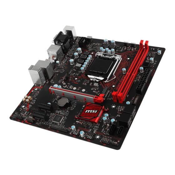
Page 8: Overview Of Components
Overview of Components CPU_FAN1 SYS_FAN2 CPU Socket CPU_PWR1 DIMMA1 DIMMB1 EZ Debug LED ATX_PWR1 SYS_FAN1 M2_1 JUSB3 PCI_E1 SATA 1 2 JBAT1 SATA 3 4 PCI_E2 JTPM1 SATA5 PCI_E3 SATA6 JCOM1 JFP2 JFP1 JAUD1 JLED1 JLPT1 JUSB2 JUSB1 JCI1 Overview of Components... -
Page 9: Cpu Socket
Always unplug the power cord from the power outlet before installing or removing the CPU. Please retain the CPU protective cap after installing the processor. MSI will deal with Return Merchandise Authorization (RMA) requests if only the motherboard comes with the protective cap on the CPU socket. -
Page 10: Dimm Slots
DIMM Slots Please install the memory module into the DIMM slot as shown below. Important To boot up the system successfully, always insert the memory module into DIMM1 first. Due to chipset resource usage, the available capacity of memory will be a little less than the amount of installed. -
Page 11: Jfp1, Jfp2: Front Panel Connectors
JFP1, JFP2: Front Panel Connectors These connectors connect to the switches and LEDs on the front panel. HDD LED + Power LED + HDD LED - Power LED - Reset Switch Power Switch Reset Switch Power Switch JFP1 Reserved No Pin HDD LED - HDD LED HDD LED +... -
Page 12: M2_1: M.2 Slot (Key M)
M2_1: M.2 Slot (Key M) Please install the M.2 solid-state drive (SSD) into the M.2 slot as shown below. Important Intel RST only supports PCIe M.2 SSD with UEFI ROM, does not support Legacy ® ROM. ATX_PWR1, CPU_PWR1: Power Connectors These connectors allow you to connect an ATX power supply. -
Page 13: Jusb1~2: Usb 2.0 Connectors
JUSB1~2: USB 2.0 Connectors These connectors allow you to connect USB 2.0 ports on the front panel. USB0- USB1- USB0+ USB1+ Ground Ground No Pin Important Note that the VCC and Ground pins must be connected correctly to avoid possible damage. -
Page 14: Cpu_Fan1, Sys_Fan1~2: Fan Connectors
CPU_FAN1, SYS_FAN1~2: Fan Connectors Fan connectors can be classified as PWM (Pulse Width Modulation) Mode and DC Mode. PWM Mode fan connectors provide constant 12V output and adjust fan speed with speed control signal. DC Mode fan connectors control fan speed by changing voltage. -
Page 15: Jtpm1: Tpm Module Connector
JTPM1: TPM Module Connector This connector is for TPM (Trusted Platform Module). Please refer to the TPM security platform manual for more details and usages. LPC Clock 3V Standby power LPC Reset 3.3V Power LPC address & data pin0 Serial IRQ LPC address &... -
Page 16: Jaud1: Front Audio Connector
JAUD1: Front Audio Connector This connector allow you to connect audio jacks on the front panel. MIC L Ground MIC R Head Phone R MIC Detection SENSE_SEND No Pin Head Phone L Head Phone Detection JCOM1: Serial Port Connector This connector allows you to connect the optional serial port with bracket. SOUT Ground No Pin... -
Page 17: Jbat1: Clear Cmos (Reset Bios) Jumper
JBAT1: Clear CMOS (Reset BIOS) Jumper There is CMOS memory onboard that is external powered from a battery located on the motherboard to save system configuration data. If you want to clear the system configuration, set the jumpers to clear the CMOS memory. Keep Data Clear CMOS/ Reset (default) -
Page 18: Bios Setup
Press Delete key, when the Press DEL key to enter Setup Menu, F11 to enter Boot Menu message appears on the screen during the boot process. Use MSI FAST BOOT application. Click on GO2BIOS button and choose OK. The system will reboot and enter BIOS setup directly. -
Page 19: Resetting Bios
Updating BIOS Updating BIOS with M-FLASH Before updating: Please download the latest BIOS file that matches your motherboard model from MSI website. And then save the BIOS file into the USB flash drive. Updating BIOS: Insert the USB flash drive that contains the update file into the computer. -
Page 20: Software Description
Note: Due to chipset limitation, during the Windows 7 installation process, USB ® optical drives and USB pen drives are not supported. You can use MSI Smart Tool to install Windows ® Press the Restart button on the computer case. - Page 21 B250M GAMING PRO ® BIOS ......................2 ........................3 ..................... 7 ...................7 ........................8 ......................9 DIMM ......................10 PCI_E1~3: PCIe .................10 JFP1, JFP2: ................11 SATA1~6: SATA 6Gb/s ................11 M2_1: M.2 (Key M) ..................12 ATX_PWR1, CPU_PWR1: ...............12 JUSB1~2: USB 2.0 .................13 JUSB3: USB 3.1 Gen1 ................13...
- Page 22 (ESD) . ESD 60 C (140 F)
- Page 23 ™ Intel Pentium Celeron ® ® ® Intel B250 ® DDR4 32GB DDR4 2400/ 2133 MHz* DDR4 2133 MHz* WWW.MSI. PCIe 3.0 x16 (x16 PCIe 3.0 x1 HDMI 4096x2160@30Hz(7 CPU), ™ 4096x2160@24Hz(6 CPU), 2560x1600@60Hz DVI-D 1920x1200@60Hz 2048x1536@50Hz, 2048x1280@60Hz, 1920x1200@60Hz Intel B250 ®...
- Page 24 PS/2 PS/2 DVI-D HDMI ™ USB 2.0 Type-A USB 3.1 Gen1 Type-A USB 3.1 Gen1 Type-C LAN (RJ45) ATX 12V SATA 6Gb/s USB 2.0 USB 2.0 4 USB 3.1 Gen1 USB 3.1 Gen1 2 RGB LED CMOS NUVOTON NCT6795 CPU/ CPU/ CPU/ m-ATX...
- Page 25 COMMAND CENTER LIVE UPDATE 6 FAST BOOT SUPER CHARGER GAMING APP RAMDISK X-BOOST MSI SMART TOOL GAMING LAN MANAGER XSplit Gamecaster V2 ® Norton™ Internet Security Solution Google Chrome™ ,Google Toolbar, Google Drive SteelSeries Engine 3 CPU-Z MSI GAMING DRAGON EYE...
- Page 26 Mystic Light Extension RGB- GAMING APP LIGHT CONTROL CLICK BIOS 5 & MILITARY CLASS 5 MSI Exclusive VGA Armor MSI Steel Armor PCI-E Steel Armor COMMAND CENTER RAMDISK LIVE UPDATE 6 X-BOOST DDR4 Boost DDR4 DDR4 De-pop audio circuit USB 3.1 Gen1 Type-C Ready...
-
Page 27: I/O
USB 2.0 PS/2 USB 3.1 Gen1 Type-A DVI-D PS/2 USB 3.1 Gen1 Type-C USB 3.1 Gen1 Type-A 10 Mbps 100 Mbps 1 Gbps JAUD1 Realtek HD Audio Manager (Realtek HD ) > Advanced Settings( [Mute the rear output device, when a front headphone plugged in](... - Page 28 CPU_FAN1 SYS_FAN2 CPU_PWR1 DIMMA1 DIMMB1 EZ Debug LED ATX_PWR1 SYS_FAN1 M2_1 JUSB3 PCI_E1 SATA 1 2 JBAT1 SATA 3 4 PCI_E2 JTPM1 SATA5 PCI_E3 SATA6 JCOM1 JFP2 JFP1 JAUD1 JLED1 JLPT1 JUSB2 JUSB1 JCI1...
-
Page 29: Cpu
, CPU (RMA) , CPU . CPU... -
Page 30: Dimm
DIMM DIMM DIMM1 (Windows OS) Windows OS PCI_E1~3: PCIe PCI_E1: PCIe 3.0 x16 PCI_E2: PCIe 3.0 x1 PCI_E3: PCIe 3.0 x1... -
Page 31: Jfp1, Jfp2
JFP1, JFP2: HDD LED + Power LED + HDD LED - Power LED - Reset Switch Power Switch Reset Switch Power Switch JFP1 Reserved No Pin HDD LED - HDD LED HDD LED + POWER LED - POWER LED POWER LED + Speaker - Buzzer + JFP2... -
Page 32: (Key M)
M2_1: M.2 (Key M) (SSD) Intel UEFI ROM PCIe M.2 SSD ® ATX_PWR1, CPU_PWR1: +3.3V +3.3V +3.3V -12V Ground Ground PS-ON# Ground Ground Ground ATX_PWR1 Ground Ground PWR OK 5VSB +12V +12V +3.3V Ground Ground +12V Ground +12V CPU_PWR1 Ground +12V Ground +12V... -
Page 33: Jusb1~2: Usb 2.0
JUSB1~2: USB 2.0 USB 2.0 USB0- USB1- USB0+ USB1+ Ground Ground No Pin iPad,iPhone iPod SUPER CHARGER ® JUSB3: USB 3.1 Gen1 USB 3.1 Gen1 Power USB2.0+ USB3_RX_DN USB2.0- USB3_RX_DP Ground Ground USB3_TX_C_DP USB3_TX_C_DN USB3_TX_C_DN USB3_TX_C_DP Ground Ground USB3_RX_DP USB2.0- USB3_RX_DN USB2.0+ Power... -
Page 34: Cpu_Fan1, Sys_Fan1~2
CPU_FAN1, SYS_FAN1~2: PWM (Pulse Width Modulation) (Non-PWM) 100% CPU_FAN1 SYS_FAN2 SYS_FAN1 Ground +12V Voltage Ground Control Speed Control Sense Signal Sense BIOS > HARDWARE MONITOR( PWM/ DC... -
Page 35: Jtpm1: Tpm
JTPM1: TPM TPM (Trusted Platform Module) LPC Clock 3V Standby power LPC Reset 3.3V Power LPC address & data pin0 Serial IRQ LPC address & data pin1 5V Power LPC address & data pin2 No Pin LPC address & data pin3 Ground LPC Frame Ground... -
Page 36: Jaud1
JAUD1: MIC L Ground MIC R Head Phone R MIC Detection SENSE_SEND No Pin Head Phone L Head Phone Detection JCOM1: SOUT Ground No Pin JLPT1: RSTB# AFD# PRND0 ERR# PRND1 PINIT# PRND2 LPT_SLIN# PRND3 Ground PRND4 Ground PRND5 Ground PRND6 Ground PRND7... -
Page 37: Jbat1: Cmos (Reset Bios)
JBAT1: CMOS (Reset BIOS) CMOS CMOS CMOS / BIOS BIOS JBAT1 5-10 JBAT1 EZ Debug LED: CPU - CPU DRAM - DRAM VGA - GPU BOOT - JLED1: RGB LED 5050 RGB LED 5050 LED +12V JLED1 3A (12V) 5050 RGB (12V/G/R/B) . -
Page 38: Bios
BIOS . BIOS BIOS BIOS BIOS HELP( BIOS BIOS Press DEL key to enter Setup Menu, F11 to enter Boot Menu(DEL , F11 Delete MSI FAST BOOT . GO2BIOS BIOS GO2BIOS Memory-Z (FAT/ FAT32 * F10 . Yes BIOS... -
Page 39: Bios
BIOS BIOS > M-FLASH > Select one file to update BIOS and ME , BIOS BIOS 100% Live Update 6 BIOS BIOS MSI LIVE UPDATE 6 Manual scan MB BIOS box Scan BIOS MB BIOS Next In Windows mode Next... -
Page 40: Windows ® 7/ 8.1/ 10
Windows 7/ 8.1/ 10 ® Windows 7/ 8.1/ 10 ® Windows ® . MSI Smart Tool(MSI Windows ® Restart Windows 8.1/ 10 . Windows ® ® , BIOS . Advanced > Windows OS Configuration > Windows 7 Installation : Windows 7... - Page 41 Merci d avoir acheté une carte mère MSI B250M GAMING ® PRO. Ce manuel de l utilisateur fournit des informations sur le schéma, la vue d ensemble des composants, la configuration du BIOS et l installation des logiciels. Table des matières Informations de sécurité...
-
Page 42: Informations De Sécurité
Informations de sécurité Les composants dans l emballage peuvent être endommagés par des décharges électrostatiques (ESD). Pour vous assurer de correctement monter votre ordinateur, veuillez vous référer aux instructions ci-dessous. Assurez-vous de bien connecter tous les composants. En cas de mauvaise connexion, il se peut que l ordinateur ne reconnaisse pas le composant et que le démarrage échoue. -
Page 43: Spécifications
Les processeurs de 6ème génération supportent DDR4 Mémoire 2133 MHz* Architecture mémoire double canal * Veuillez vous référer au site www.msi.com pour plus d informations sur la mémoire compatible. 1 x slot PCIe 3.0 x16 (support mode x16) Slots d extension 2 x slots PCIe 3.0 x1... - Page 44 Suite du tableau de la page précédente 1 x contrôleur Intel I219-V Gigabit LAN 1 x port clavier PS/2 1 x port souris PS/2 1 x port VGA 1 x port DVI-D Connecteurs 1 x port HDMI ™ sur le panneau 2 x ports USB 2.0 Type-A arrière 3 x ports USB 3.1 Gen1 Type-A...
- Page 45 Amélioration du réseau multiserveur Réduction du lag et des risques de déconnexion *Cette fonctionnalité dépend d une offre limitée dans le temps. Veuillez vous référer au site www.msi.com pour plus d informations. Suite du tableau sur la page suivante Spécifications...
- Page 46 Protection contre les interférences électromagnétiques Fonctions Protection contre l humidité spéciales MSI Protection du circuit Protection contre la hausse de température Slot VGA Armor MSI Steel Armor Steel Armor PCI-E COMMAND CENTER Moniteur système Contrôle des ventilateurs RAMDISK LIVE UPDATE 6 X-BOOST Amélioration des performances du système...
-
Page 47: Panneau Arrière Entrée/ Sortie
Panneau arrière Entrée/ Sortie Ligne-entrée USB 2.0 Ligne-sortie Souris PS/2 USB 3.1 Gen1 Type-A DVI-D Mic entrée Clavier PS/2 USB 3.1 Gen1 Type-C USB 3.1 Gen1 Type-A Tableau explicatif de l état de la LED du port LAN LED indiquant la connexion LED indiquant la vitesse et l activité... -
Page 48: Vue D Ensemble Des Composants
Vue d ensemble des composants CPU_FAN1 SYS_FAN2 Socket processeur CPU_PWR1 DIMMA1 DIMMB1 EZ Debug LED ATX_PWR1 SYS_FAN1 M2_1 JUSB3 PCI_E1 SATA 1 2 JBAT1 SATA 3 4 PCI_E2 JTPM1 SATA5 PCI_E3 SATA6 JCOM1 JFP2 JFP1 JAUD1 JLED1 JLPT1 JUSB2 JUSB1 JCI1 Vue d ensemble des composants... -
Page 49: Socket Processeur
électrique. Veuillez garder le capot de protection du processeur après l installation du processeur. Selon les exigences de RMA (Return Merchandise Authorization), MSI n acceptera pas les cartes mère dont le capot de protection aura été retiré. -
Page 50: Slots Dimm
Slots DIMM Insérer le module de mémoire dans l emplacement DIMM comme indiqué ci- dessous. Important Pour réussir à démarrer le système, veuillez à toujours insérer un module de mémoire dans l emplacement DIMM1 en premier. Du fait des ressources utilisées par le chipset, la capacité de mémoire disponible est un peu moins élevée que celle installée. -
Page 51: Jfp1, Jfp2: Connecteurs De Panneau Avant
JFP1, JFP2: Connecteurs de panneau avant Ces connecteurs se lient aux interrupteurs et indicateurs LED du panneau avant. HDD LED + Power LED + HDD LED - Power LED - Reset Switch Power Switch Reset Switch Power Switch JFP1 Reserved No Pin HDD LED - HDD LED... -
Page 52: M2_1: Slot M.2 (Touche M)
M2_1: Slot M.2 (Touche M) Installer le disque dur M.2 dans le slot M.2 comme indiqué ci-dessous. Important La technologie Intel RST supporte seulement un SSD M.2 PCIe avec une mémoire ® ROM UEFI et non avec une mémoire ROM Legacy. ATX_PWR1, CPU_PWR1: Connecteurs d alimentation Ces connecteurs vous permettent de relier une alimentation ATX. -
Page 53: Jusb1~2: Connecteurs Usb 2.0
Notez que les broches VCC et Terre doivent être branchées correctement afin d éviter tout dommage sur la carte mère. Pour recharger votre tablette, smartphone ou autre périphérique par l intermédiaire d un port USB, veuillez installer l utilitaire MSI SUPER CHARGER. ®... -
Page 54: Cpu_Fan1, Sys_Fan1~2: Connecteurs Pour Ventilateurs
CPU_FAN1, SYS_FAN1~2: Connecteurs pour ventilateurs Les connecteurs pour ventilateurs peuvent être utilisés en mode PWM (Pulse Width Modulation) et en mode DC. En mode PWM, les connecteurs fournissent une sortie de 12V constante et ajustent la vitesse des ventilateurs avec un signal de contrôle de vitesse. -
Page 55: Jtpm1: Connecteur De Module Tpm
JTPM1: Connecteur de module TPM Ce connecteur est relié à un module TPM (Trusted Platform Module). Veuillez vous référer au manuel du module TPM pour plus d informations. LPC Clock 3V Standby power LPC Reset 3.3V Power LPC address & data pin0 Serial IRQ LPC address &... -
Page 56: Jaud1: Connecteur Audio Avant
JAUD1: Connecteur audio avant Ce connecteur se lie aux jacks audio du panneau avant. MIC L Ground MIC R Head Phone R MIC Detection SENSE_SEND No Pin Head Phone L Head Phone Detection JCOM1: Connecteur de port série Ce connecteur vous permet de relier un port série en option. SOUT Ground No Pin... -
Page 57: Jbat1: Cavalier Clear Cmos (Réinitialisation Bios)
JBAT1: Cavalier clear CMOS (Réinitialisation BIOS) Une mémoire CMOS est intégrée et est alimentée en externe par une batterie située sur la carte mère afin de conserver les données de configuration système. Si vous souhaitez nettoyer la configuration système, placez le cavalier sur Effacer CMOS de manière à... -
Page 58: Configuration Du Bios
Menu, F11 to enter Boot Menu sur l écran, veuillez appuyer sur la touche Suppr. Quand l ordinateur est déjà en marche, vous pouvez utiliser l application MSI FAST BOOT. Cliquez sur le bouton GO2BIOS puis sur OK. Le système redémarre et entre dans l interface Setup du BIOS. -
Page 59: Réinitialiser Le Bios
Avant la mise à jour : Veuillez télécharger la dernière version de BIOS compatible à votre carte mère sur le site MSI. Ensuite, veuillez sauvegarder le nouveau BIOS sur le lecteur flash USB. Mettre le BIOS à jour : Connectez le lecteur Flash USB contenant le profil à l ordinateur. -
Page 60: Informations Sur Les Logiciels
Remarque : Du fait des limites du chipset pendant l installation de Windows ® les lecteurs optiques USB et les clés USB ne seront pas supportés. Vous pouvez utiliser MSI Smart Tool pour installer Windows ® Appuyez sur le bouton Restart du boîtier de l ordinateur. - Page 61 Danke, dass Sie sich für das MSI B250M GAMING PRO ® Motherboard entschieden haben. Dieses Handbuch gibt informationen über Motherboard-Layout, Komponentenübersicht, BIOS-Setup und Softwareinstallation. Inhalt Sicherheitshinweis ..................2 Spezifikationen ....................3 Rückseite E/A ....................7 LAN Port LED Zustandstabelle ................7 Übersicht der Komponenten ................
-
Page 62: Sicherheitshinweis
Sicherheitshinweis Die im Paket enthaltene Komponenten sind der Beschädigung durch elektrostatischen Entladung (ESD). Beachten Sie bitte die folgenden Hinweise, um die erfolgreichen Computermontage sicherzustellen. Stellen Sie sicher, dass alle Komponenten fest angeschlossen sind. Lockere Steckverbindungen können Probleme verursachen, zum Beispiel: Der Computer erkennt eine Komponente nicht oder startet nicht. -
Page 63: Spezifikationen
2400/ 2133 MHz* Intel Prozessoren der 6. Generation unterstützen DDR4 Speicher 2133 MHz* Dual-Kanal-Speicherarchitektur * Weitere Informationen zu kompatiblen Speicher finden Sie unter: http://www.msi.com. 1x PCIe 3.0 x16 Steckplatz (unterstützt x16 Modus) Erweiterung- anschlüsse 2x PCIe 3.0 x1 Steckplätze 1x HDMI Anschluss, Unterstützung einer maximalen... - Page 64 Fortsetzung der vorherigen Seite Realtek ALC887 Codec ® Audio 7.1-Kanal-HD-Audio 1x Intel I219-V Gigabit LAN Controller PS/2 Tastaturanschluss x1 PS/2 Mausanschluss x1 VGA Anschluss x1 DVI-D Anschluss x1 HDMI Anschluss x1 ™ Hintere Ein-/ und Ausgänge USB 2.0 Typ-A Anschlüsse x2 USB 3.1 Gen1 Typ-A Anschlüsse x3 USB 3.1 Gen1 Typ-C Anschluss x1 LAN (RJ45) Anschluss x1...
- Page 65 XSplit GAMECASTER XSplit BROADCASTER GAMING CERTIFIED WTFast GPN* 2-Monate Premiumlizenz Multiserver-Netzwerkoptimierung Verbesserte Reduktion von Lag Spikes & Verbindungseinbrüchen * Dieses Angebot steht nur für begrenzte Zeit zur Verfügung, weitere Informationen finden Sie unter www.msi.com Fortsetzung auf der nächsten Seite Spezifikationen...
- Page 66 MILITARY CLASS 5 Military Class Komponenten Military Class Stabilität und Zuverlässigkeit ESD-Schutz EMI-Schutz Luftfeuchtigkeit Schutz MSI Exclusive Schaltkreisschutz Features Übertemperaturschutz VGA Armor Steckplatz MSI Steel Armor PCI-E Steel Armor COMMAND CENTER System-Monitor Smart-Lüftersteuerung RAMDISK LIVE UPDATE 6 X-BOOST Systemleistungsverbesserung Nutzer-Profile...
-
Page 67: Rückseite E/A
Rückseite E/A Line-In Line-Out USB 2.0 PS/2 Maus USB 3.1 Gen1 Typ-A DVI-D Mic In PS/2 Tastatur USB 3.1 Gen1 Typ-C USB 3.1 Gen1 Typ-A LAN Port LED Zustandstabelle Verbindung/ Aktivität LED Geschwindigkeit LED Zustand Bezeichnung Zustand Bezeichnung 10 Mbps-Verbindung Keine Verbindung Grün... -
Page 68: Übersicht Der Komponenten
Übersicht der Komponenten CPU_FAN1 SYS_FAN2 CPU Sockel CPU_PWR1 DIMMA1 DIMMB1 EZ Debug LED ATX_PWR1 SYS_FAN1 M2_1 JUSB3 PCI_E1 SATA 1 2 JBAT1 SATA 3 4 PCI_E2 JTPM1 SATA5 PCI_E3 SATA6 JCOM1 JFP2 JFP1 JAUD1 JLED1 JLPT1 JUSB2 JUSB1 JCI1 Übersicht der Komponenten... -
Page 69: Cpu Socket
Ziehen Sie das Netzkabel ab, bevor Sie CPU ein- und ausbauen. Bitte bewahren Sie die CPU Schutzkappe nach der Installation des Prozessors auf. MSI wird RMA (Return Merchandise Authorization) Anfragen nur dann behandeln, wenn die Schutzklappe auf dem CPU-Sockel des Motherboards sitzt. -
Page 70: Dimm-Steckplätze
DIMM-Steckplätze Setzen Sie bitte ein Speichermodul wie untern gezeigt in den DIMM-Steckplatz ein. Wichtig Um einen sicheren Systemstart zu gewährleisten, bestücken Sie immer DIMM1 zuerst. Aufgrund der Chipsatzressourcennutzung wird die verfügbare Kapazität des Speichers kleiner sein als die Größe der installierten Speicherkapazität. Bitte beachten Sie, dass die maximale Kapazität eines 32-Bit-Windows- Betriebssystem bei 4GB oder weniger liegt. -
Page 71: Jfp1, Jfp2: Frontpanel-Anschlüsse
JFP1, JFP2: Frontpanel-Anschlüsse Diese Anschlüsse verbinden mit den Schaltern und LEDs auf des Frontpanels. HDD LED + Power LED + HDD LED - Power LED - Reset Switch Power Switch Reset Switch Power Switch JFP1 Reserved No Pin HDD LED - HDD LED HDD LED + POWER LED -... -
Page 72: M2_1: M.2 Steckplatz (Key M)
M2_1: M.2 Steckplatz (Key M) Bitte installieren Sie das M.2 Solid-State-Laufwerke (SSD) in den M.2 Steckplatz (siehe unten). Wichtig Intel RST unterstützt nur PCIe M.2 SSD mit UEFI ROM, Legacy-ROM wird NICHT ® unterstützt. ATX_PWR1, CPU_PWR1: Stromanschlüsse Mit diesen Anschlüssen verbinden Sie die ATX Stromstecker. +3.3V +3.3V +3.3V... -
Page 73: Jusb1~2: Usb 2.0 Anschlüsse
Bitte beachten Sie, dass Sie die mit VCC (Stromführende Leitung) und Ground (Erdleitung) bezeichneten Pins korrekt verbinden müssen, ansonsten kann es zu Schäden kommen. Um das iPad, iPhone und iPod über USB-Anschlüsse aufzuladen, installieren Sie bitte die MSI SUPER CHARGER Software. ® JUSB3: USB 3.1 Gen1 Anschluss Mit diesem Anschluss können Sie den USB 3.1 Gen1 Anschluss auf dem Frontpanel... -
Page 74: Cpu_Fan1, Sys_Fan1~2: Stromanschlüsse Für Lüfter
CPU_FAN1, SYS_FAN1~2: Stromanschlüsse für Lüfter Diese Anschlüsse können im PWM (Pulse Width Modulation) Modus oder Spannungsmodus betrieben werden. Im PWM-Modus bieten die Lüfteranschlüsse konstante 12V Ausgang und regeln die Lüftergeschwindigkeit per Drehzahlsteuersignal. Im DC-Modus bestimmen die Lüfteranschlüsse die Lüftergeschwindigkeit durch Ändern der Spannung. Wenn Sie ein 3-Pin (Non-PWM) Lüfter an einen PWM-Modus Lüfteranschluss anschließen, läuft der Lüfter mit höchster Drehzahl und kann unangenehm laut werden. -
Page 75: Jtpm1: Tpm Anschluss
JTPM1: TPM Anschluss Dieser Anschluss wird für das TPM Modul (Trusted Platform Module) verwendet. Weitere Informationen über den Einsatz des optionalen TPM Modules entnehmen Sie bitte dem TPM Plattform Handbuch. LPC Clock 3V Standby power LPC Reset 3.3V Power LPC address & data pin0 Serial IRQ LPC address &... -
Page 76: Jaud1: Audioanschluss Des Frontpanels
JAUD1: Audioanschluss des Frontpanels Dieser Anschluss ermöglicht den Anschluss von Audiobuchsen eines Frontpanels. MIC L Ground MIC R Head Phone R MIC Detection SENSE_SEND No Pin Head Phone L Head Phone Detection JCOM1: Serieller Anschluss Mit diesem Anschluss können Sie das optionale serielle Schnittstelle mit dem Einbausatze verbinden. -
Page 77: Jbat1: Clear Cmos Steckbrücke (Reset Des Bios)
JBAT1: Clear CMOS Steckbrücke (Reset des BIOS) Der Onboard CMOS Speicher (RAM) wird durch eine externe Spannungsversorgung durch eine Batterie auf dem Motherboard versorgt, um die Daten der Systemkonfiguration zu speichern. Wenn Sie die Systemkonfiguration löschen wollen, müssen Sie die Steckbrücke für kurze Zeit umsetzen. Daten beibehalten CMOS-Daten löschen/ Reset des BIOS... -
Page 78: Bios-Setup
Während des BOOT-Vorgangs drücken Sie die Taste Delete, wenn die Meldung Press DEL key to enter Setup Menu, F11 to enter Boot Menu erscheint. Verwenden Sie die MSI FAST BOOT Anwendung. Klicken Sie die GO2BIOS-Taste und drücken OK. Das System startet neu und geht direkt ins BIOS. -
Page 79: Reset Des Bios
Aktualisierung des BIOS mit dem M-FLASH-Programm Vorbereitung: Laden Sie bitte die neueste BIOS Version, die dem Motherboard-Modell entspricht, von der offiziellen MSI Website herunter und speichern Sie die BIOS-Datei auf USB- Flash-Laufwerk. BIOS-Aktualisierungsschritte: Schließen das USB-Flashlaufwerk mit der BIOS-Datei an den Computer. -
Page 80: Softwarebeschreibung
7 Installationsprozesses keine optischen Laufwerke und USB-Laufwerke oder USB-Sticks unterstützt.Zur einfachen Windows 7-Installation können Sie das ® MSI Smart Tool to install Windows ® Drücken Sie die Taste Restart auf dem Computergehäuse. Für Windows 8.1/ 10, überspringen Sie diesen Schritt. Für Windows 7, gehen Sie ®... - Page 81 B250M GAMING PRO. ® BIOS ..........2 ..............3 ..........7 LAN ..........7 ............8 ..................9 DIMM ....................10 PCI_E1~3: PCIe ............10 JFP1, JFP2: .............11 SATA1~6: SATA 6 / ..............11 M2_1: M.2 ( M) ................12 ATX_PWR1, CPU_PWR1: ........12 JUSB1~2: USB 2.0 ................13 JUSB3: USB 3.1 Gen1 .................13 CPU_FAN1, SYS_FAN1~2:...
- Page 82 60 C (140...
- Page 83 Pentium Celeron 6- / 7- ® ® LGA1151 Intel B250 ® 2x DDR4 DDR4 2400/ 2133 DDR4 2133 www.msi.com PCIe 3.0 x16 ( x16) PCIe 3.0 x1 HDMI ™ 4096x2160@30 ), 4096x2160@24 ), 2560x1600@60 DVI-D, 1920x1200@60 VGA, 2048x1536@50 , 2048x1280@60...
- Page 84 Realtek ALC887 Codec ® 7.1- High Definition Audio Intel I219-V PS/2 PS/2 DVI-D HDMI ™ USB 2.0 Type-A USB 3.1 Gen1 Type-A USB 3.1 Gen1 Type-C LAN (RJ45) 1x 24- ATX 12 SATA 6 USB 2.0 ( USB 2.0) USB 3.1 Gen1 ( USB 3.1 Gen1) 1x 4- 2x 4-...
- Page 85 BIOS ACPI 5.0, PnP 1.0a, SM BIOS 2.8 COMMAND CENTER LIVE UPDATE 6 FAST BOOT SUPER CHARGER GAMING APP RAMDISK X-BOOST MSI SMART TOOL GAMING LAN MANAGER XSplit Gamecaster V2 Intel Extreme Tuning Utility ® Norton Internet Security Solution ™...
- Page 86 Dedicated header for 4-pin RGB-strip Lighting control via GAMING APP CLICK BIOS 5 Board Explorer Hardware Monitor MILITARY CLASS 5 Military Class Military Class VGA Armor MSI Steel Armor PCI-E Steel Armor COMMAND CENTER RAMDISK LIVE UPDATE 6 X-BOOST DDR4 Boost DDR4 DDR4...
-
Page 87: Lan
USB 2.0 PS/2 USB 3.1 Gen1 Type-A DVI-D PS/2 USB 3.1 Gen1 Type-C USB 3.1 Gen1 Type-A Audio 7.1- JAUD1. Realteck HD Audio Manager > Advanced Settings, Mute the rear output device, when a front headphone plugged in. - Page 88 CPU_FAN1 SYS_FAN2 CPU_PWR1 DIMMA1 DIMMB1 EZ Debug LED ATX_PWR1 SYS_FAN1 M2_1 JUSB3 PCI_E1 SATA 1 2 JBAT1 SATA 3 4 PCI_E2 JTPM1 SATA5 PCI_E3 SATA6 JCOM1 JFP2 JFP1 JAUD1 JLED1 JLPT1 JUSB2 JUSB1 JCI1...
- Page 89 , MSI...
-
Page 90: Dimm
DIMM DIMM, DIMM1 Windows, Windows. PCI_E1~3: PCIe PCI_E1: PCIe 3.0 x16 PCI_E2: PCIe 3.0 x1 PCI_E3: PCIe 3.0 x1... - Page 91 JFP1, JFP2: HDD LED + Power LED + HDD LED - Power LED - Reset Switch Power Switch Reset Switch Power Switch JFP1 Reserved No Pin HDD LED - HDD LED HDD LED + POWER LED - POWER LED POWER LED + Speaker - Buzzer + JFP2...
-
Page 92: Atx_Pwr1, Cpu_Pwr1
M2_1: M.2 ( (SSD) M.2 M.2, Intel PCIe M.2 SSD UEFI ROM ® Legacy ROM. ATX_PWR1, CPU_PWR1: ATX. +3.3V +3.3V +3.3V -12V Ground Ground PS-ON# Ground Ground Ground ATX_PWR1 Ground Ground PWR OK 5VSB +12V +12V +3.3V Ground Ground +12V Ground +12V CPU_PWR1... - Page 93 JUSB1~2: USB 2.0 USB 2.0 USB0- USB1- USB0+ USB1+ Ground Ground No Pin iPad, iPhone iPod USB, SUPER CHARGER. ® JUSB3: USB 3.1 Gen1 USB 3.1 Gen1 Power USB2.0+ USB3_RX_DN USB2.0- USB3_RX_DP Ground Ground USB3_TX_C_DP USB3_TX_C_DN USB3_TX_C_DN USB3_TX_C_DP Ground Ground USB3_RX_DP USB2.0- USB3_RX_DN...
-
Page 94: Cpu_Fan1, Sys_Fan1~2
CPU_FAN1, SYS_FAN1~2: : PWM (PulseWidth Modulation) 12 , (Non-PWM) PWM, CPU_FAN1 SYS_FAN2 SYS_FAN1 Ground +12V Voltage Ground Control Speed Control Sense Signal Sense BIOS > HARDWARE MONITOR : PWM PWM/ DC. -
Page 95: Jci1
JTPM1: (Trusted Platform Module). LPC Clock 3V Standby power LPC Reset 3.3V Power LPC address & data pin0 Serial IRQ LPC address & data pin1 5V Power LPC address & data pin2 No Pin LPC address & data pin3 Ground LPC Frame Ground JCI1:... -
Page 96: Jaud1
JAUD1: MIC L Ground MIC R Head Phone R MIC Detection SENSE_SEND No Pin Head Phone L Head Phone Detection JCOM1: SOUT Ground No Pin JLPT1: RSTB# AFD# PRND0 ERR# PRND1 PINIT# PRND2 LPT_SLIN# PRND3 Ground PRND4 Ground PRND5 Ground PRND6 Ground PRND7... -
Page 97: Ez Debug Led
JBAT1: CMOS ( BIOS) CMOS CMOS BIOS BIOS JBAT1 5-10 JBAT1. EZ Debug LED: CPU - DRAM - DRAM VGA - BOOT - JLED1: RGB LED 5050 RGB. 5050 LED +12V JLED1 5050 RGB (12 /G/R/B) 3 (12 ). RGB, GAMING APP... -
Page 98: Bios
BIOS BIOS, BIOS BIOS BIOS, HELP. BIOS BIOS. Delete, Press DEL key to enter Setup Menu, F11 to enter Boot Menu MSI FAST BOOT. GO2BIOS BIOS. GO2BIOS Memory-Z FAT / FAT32 BIOS... -
Page 99: Bios
BIOS: USB, BIOS POST. BIOS > M-FLASH > Select one file to update BIOS, BIOS BIOS. BIOS Live Update 6 BIOS: MSI LIVE UPDATE 6. Manual scan. MB BIOS Scan. MB BIOS BIOS. Next In Windows mode. BIOS. Next Start... - Page 100 Windows 7/ 8.1/ 10 ® Windows 7/ 8.1/ 10 ® Windows 7, USB ® MSI Smart Tool Windows ® Restart Windows 8.1/ 10, Windows ® ® BIOS Advanced > Windows OS Configuration > Windows 7 Installation Windows ® / USB...
- Page 101 B250M GAMING PRO ® BIOS ......................2 ........................3 ....................7 ..................7 ......................8 ......................9 DIMM ......................10 PCI_E1~3: PCIe .................10 JFP1, JFP2: ................11 SATA1~6: SATA 6Gb/s ................11 M2_1: M.2 (M Key) ..................12 ATX_PWR1, CPU_PWR1: ..............12 JUSB1~2: USB 2.0 ..................13 JUSB3: USB 3.1 Gen1 ................13...
- Page 102 (ESD) (ESD)
- Page 103 ™ Intel Pentium Celeron ® ® ® Intel B250 ® DDR4 32GB DDR4 2400/ 2133 MHz* DDR4 2133 MHz* www.msi.com PCIe 3.0 x16 PCIe 3.0 x1 HDMI 4096x2160@30Hz( ™ CPU), 4096x2160@24Hz( CPU), 2560x1600@60Hz DVI-D 1920x1200@60Hz 2048x1536@50Hz, 2048x1280@60Hz, 1920x1200@60Hz Intel B250 ®...
- Page 104 PS/2 PS/2 DVI-D HDMI ™ USB 2.0 Type-A USB 3.1 Gen1 Type-A USB 3.1 Gen1 Type-C LAN (RJ45) 24-pin ATX 8-pin ATX 12V SATA 6Gb/s USB 2.0 USB 2.0 USB 3.1 Gen1 USB 3.1 Gen1 4-pin CPU 4-pin RGB LED CMOS NUVOTON NCT6795 CPU/...
- Page 105 COMMAND CENTER LIVE UPDATE 6 GAMING APP GAMING Xsplit Gamecaster ® ™ Google ™ Google Google SteelSeries Engine MSI GAMING CPU-Z DRAGON EYE GAMING Intel ® GAMING cFos XSplit XSplit GAMECASTER XSplit BROADCASTER GAMING WTFast GPN* www.msi.com...
- Page 106 GAMING APP BIOS MSI PCI-E PCI-E COMMAND CENTER LIVE UPDATE 6 DDR4 DDR4 DDR4 USB 3.1 Gen1 Type-C...
-
Page 107: I/O
USB 2.0 PS/2 USB 3.1 Gen1 Type-A DVI-D PS/2 USB 3.1 Gen1 Type-C USB 3.1 Gen1 Type-A 10 Mbps 100 Mbps 1 Gbps 7.1- JAUD1 Realtek HD Audio Manager > Advanced Settings Mute the rear output device, when a front headphone plugged in... - Page 108 CPU_FAN1 SYS_FAN2 CPU_PWR1 DIMMA1 DIMMB1 EZ Debug LED ATX_PWR1 SYS_FAN1 M2_1 JUSB3 PCI_E1 SATA 1 2 JBAT1 SATA 3 4 PCI_E2 JTPM1 SATA5 PCI_E3 SATA6 JCOM1 JFP2 JFP1 JAUD1 JLED1 JLPT1 JUSB2 JUSB1 JCI1...
-
Page 109: Cpu
(RMA) -
Page 110: Dimm
DIMM DIMM DIMM1 Windows Windows PCI_E1~3: PCIe PCI_E1: PCIe 3.0 x16 PCI_E2: PCIe 3.0 x1 PCI_E3: PCIe 3.0 x1... -
Page 111: Jfp1, Jfp2
JFP1, JFP2: HDD LED + Power LED + HDD LED - Power LED - Reset Switch Power Switch Reset Switch Power Switch JFP1 Reserved No Pin HDD LED - HDD LED HDD LED + POWER LED - POWER LED POWER LED + Speaker - Buzzer + JFP2... -
Page 112: (M Key)
M2_1: M.2 (M Key) (SSD) Intel UEFI ROM PCIe M.2 Legacy ROM ® ATX_PWR1, CPU_PWR1: +3.3V +3.3V +3.3V -12V Ground Ground PS-ON# Ground Ground Ground ATX_PWR1 Ground Ground PWR OK 5VSB +12V +12V +3.3V Ground Ground +12V Ground +12V CPU_PWR1 Ground +12V Ground... -
Page 113: Jusb1~2: Usb 2.0
JUSB1~2: USB 2.0 USB 2.0 USB0- USB1- USB0+ USB1+ Ground Ground No Pin iPad iPhone iPod SUPER ® CHARGER JUSB3: USB 3.1 Gen1 USB 3.1 Gen1 Power USB2.0+ USB3_RX_DN USB2.0- USB3_RX_DP Ground Ground USB3_TX_C_DP USB3_TX_C_DN USB3_TX_C_DN USB3_TX_C_DP Ground Ground USB3_RX_DP USB2.0- USB3_RX_DN USB2.0+... -
Page 114: Cpu_Fan1, Sys_Fan1~2
CPU_FAN1, SYS_FAN1~2: PWM ( ( -PWM) 100% CPU_FAN1 SYS_FAN2 SYS_FAN1 Ground +12V Voltage Ground Control Speed Control Sense Signal Sense BIOS > HARDWARE MONITOR PWM/ DC... -
Page 115: Jci1
JTPM1: TPM TPM ( LPC Clock 3V Standby power LPC Reset 3.3V Power LPC address & data pin0 Serial IRQ LPC address & data pin1 5V Power LPC address & data pin2 No Pin LPC address & data pin3 Ground LPC Frame Ground JCI1:... -
Page 116: Jaud1
JAUD1: MIC L Ground MIC R Head Phone R MIC Detection SENSE_SEND No Pin Head Phone L Head Phone Detection JCOM1: SOUT Ground No Pin JLPT1: RSTB# AFD# PRND0 ERR# PRND1 PINIT# PRND2 LPT_SLIN# PRND3 Ground PRND4 Ground PRND5 Ground PRND6 Ground PRND7... -
Page 117: Jbat1: Cmos ( Bios)
JBAT1: CMOS ( BIOS) CMOS CMOS CMOS/ BIOS BIOS JBAT1 5-10 JBAT1 EZ Debug LED: CPU - DRAM - DRAM VGA - JLED1: RGB LED 5050 RGB LED 5050 LED +12V JLED1 5050 RGB (12V/G/R/B) 3A (12V) RGB LED GAMING APP... -
Page 118: Bios
BIOS BIOS BIOS BIOS BIOS BIOS Press DEL key to enter Setup Menu, F11 to enter Boot Menu Delete MSI FAST BOOT GO2BIOS BIOS GO2BIOS Favorites Memory-Z FAT/ FAT32 BIOS... - Page 119 POST BIOS BIOS > M-FLASH > Select one file to update BIOS and ME BIOS BIOS 100% Live Update 6 BIOS BIOS MSI LIVE UPDATE 6 Manual scan MB BIOS Scan MB BIOS BIOS BIOS Next In Windows mode Next...
- Page 120 Windows 7/ 8.1/ 10 ® Windows 7/ 8.1/ 10 ® Windows ® Windows MSI Smart Tool ® Restart windows 8.1/ 10 Windows 7 BIOS Advanced > Windows OS Configuration > Windows 7 Installation Windows 7 /USB POST( Press any key to boot from CD or DVD...
- Page 121 B250M GAMING PRO ® BIOS ......................2 ....................... 3 I/O ......................7 ..................7 ......................8 ......................9 .......................10 PCI_E1~3 PCIe .................10 JFP1, JFP2 ................11 SATA1~6 SATA 6Gb/s ................11 M2_1 M.2 (Key M) ..................12 ATX_PWR1, CPU_PWR1 ..............12 JUSB1~2 USB 2.0 ..................13 JUSB3 USB 3.1 Gen1 ................13...
- Page 122 (ESD) 60 C (140 F)
- Page 123 Intel Pentium Celeron ® ® ® Intel B250 ® DDR4 32GB DDR4 2400/ 2133 MHz* DDR4 2133 MHz* http://www.msi.com PCIe 3.0 x16 PCIe 3.0 x1 HDMI 4096x2160@30Hz(7th ™ CPU), 4096x2160@24Hz(6th CPU), 2560x1600@60Hz DVI-D 1920x1200@60Hz 2048x1536@50Hz, 2048x1280@60Hz, 1920x1200@60Hz Intel B250 ®...
- Page 124 PS/2 PS/2 DVI-D HDMI ™ USB 2.0 Type-A USB 3.1 Gen1 Type-A USB 3.1 Gen1 Type-C LAN (RJ45) 24-pin ATX 8-pin ATX 12V SATA 6Gb/s USB 2.0 USB 2.0 USB 3.1 Gen1 USB 3.1 Gen1 4-pin CPU 4-pin RGB LED CMOS NUVOTON NCT6795 CPU/...
- Page 125 COMMAND CENTER LIVE UPDATE 6 FAST BOOT SUPER CHARGER GAMING APP RAMDISK X-BOOST MSI SMART TOOL GAMING LAN MANAGER XSplit Gamecaster V2 Intel Extreme Tuning Utility ® Norton™ Internet Security Solution Google Chrome Google Google ™ SteelSeries Engine 3 CPU-Z MSI GAMING...
- Page 126 4 pin GAMING APP CLICK BIOS 5 Board Explorer PCI-E COMMAND CENTER RAMDISK LIVE UPDATE 6 X-BOOST DDR4 Boost DDR4 DDR4 USB 3.1 Gen1 Type-C...
- Page 127 USB 2.0 PS/2 USB 3.1 Gen1 Type-A DVI-D PS/2 USB 3.1 Gen1 Type-C USB 3.1 Gen1 Type-A 10 Mbps 100 Mbps 1 Gbps I / O JAUD1 Realtek HD Audio Manager > Advanced Settings I / O...
- Page 128 CPU_FAN1 SYS_FAN2 CPU_PWR1 DIMMA1 DIMMB1 EZ Debug LED ATX_PWR1 SYS_FAN1 M2_1 JUSB3 PCI_E1 SATA 1 2 JBAT1 SATA 3 4 PCI_E2 JTPM1 SATA5 PCI_E3 SATA6 JCOM1 JFP2 JFP1 JAUD1 JLED1 JLPT1 JUSB2 JUSB1 JCI1...
- Page 129 Return Merchandise Authorization (RMA)
- Page 130 DIMM DIMM1 Windows Windows PCI_E1~3 PCIe PCI_E1: PCIe 3.0 x16 PCI_E2: PCIe 3.0 x1 PCI_E3: PCIe 3.0 x1...
- Page 131 JFP1, JFP2 HDD LED + Power LED + HDD LED - Power LED - Reset Switch Power Switch Reset Switch Power Switch JFP1 Reserved No Pin HDD LED - HDD LED HDD LED + POWER LED - POWER LED POWER LED + Speaker - Buzzer + JFP2...
- Page 132 M2_1 M.2 (Key M) (SSD) Intel PCIe M.2 SSD UEFI ROM Legacy ROM ® ATX_PWR1, CPU_PWR1 +3.3V +3.3V +3.3V -12V Ground Ground PS-ON# Ground Ground Ground ATX_PWR1 Ground Ground PWR OK 5VSB +12V +12V +3.3V Ground Ground +12V Ground +12V CPU_PWR1 Ground +12V...
- Page 133 JUSB1~2 USB 2.0 USB 2.0 USB0- USB1- USB0+ USB1+ Ground Ground No Pin iPad iPhone iPod SUPER CHARGER ® JUSB3 USB 3.1 Gen1 USB 3.1 Gen1 Power USB2.0+ USB3_RX_DN USB2.0- USB3_RX_DP Ground Ground USB3_TX_C_DP USB3_TX_C_DN USB3_TX_C_DN USB3_TX_C_DP Ground Ground USB3_RX_DP USB2.0- USB3_RX_DN USB2.0+...
- Page 134 CPU_FAN1, SYS_FAN1~2 (PWM) PWM) 100% CPU_FAN1 SYS_FAN2 SYS_FAN1 Ground +12V Voltage Ground Control Speed Control Sense Signal Sense BIOS > HARDWARE MONITOR PWM / DC...
- Page 135 JTPM1 TPM (TPM) LPC Clock 3V Standby power LPC Reset 3.3V Power LPC address & data pin0 Serial IRQ LPC address & data pin1 5V Power LPC address & data pin2 No Pin LPC address & data pin3 Ground LPC Frame Ground JCI1 JCI1...
- Page 136 JAUD1 MIC L Ground MIC R Head Phone R MIC Detection SENSE_SEND No Pin Head Phone L Head Phone Detection JCOM1 SOUT Ground No Pin JLPT1 RSTB# AFD# PRND0 ERR# PRND1 PINIT# PRND2 LPT_SLIN# PRND3 Ground PRND4 Ground PRND5 Ground PRND6 Ground PRND7...
- Page 137 JBAT1 CMOS ( BIOS) CMOS CMOS RAM CMOS CMOS/ BIOS BIOS JBAT1 5-10 JBAT1 EZ Debug LED CPU - DRAM - DRAM VGA - BOOT - JLED1 RGB LED RGB LED 5050 LED +12V JLED1 5050 RGB (12V/G/R/B) 3A 12V RGB LED GAMING APP...
- Page 138 BIOS BIOS BIOS BIOS BIOS HELP BIOS BIOS Boot Menu Delete MSI FAST BOOT GO2BIOS BIOS GO2BIOS Memory-Z FAT / FAT32 BIOS...
- Page 139 BIOS BIOS > M-FLASH > Select one file to update BIOS and ME BIOS BIOS 100% Live Update 6 BIOS BIOS MSI LIVE UPDATE 6 MB BIOS Scan ( MB BIOS BIOS Next ( In Windows mode Next ( Start (...
- Page 140 Windows 7/ 8.1/ 10 ® Windows 7/ 8.1/ 10 ® Windows ® Win7 Smart Tool Windows ® Windows 8.1/ 10 Windows BIOS ® Advanced > Windows OS Configuration > Windows 7 Installation Windows ® (POST) Press any key to boot from CD or DVD... Windows 7/ 8.1/ 10 ®...
- Page 141 B250M GAMING PRO ® BIOS ..................2 ........................3 ....................7 ..................7 ..................8 ......................9 DIMM ....................10 PCI_E1~3: PCIe ................10 JFP1 JFP2: .............11 SATA1~6: SATA 6Gb/s ..............11 M2_1: M.2 (Key M) ................12 ATX_PWR1 CPU_PWR1: ............12 JUSB1~2: USB 2.0 ................13 JUSB3: USB 3.1 Gen1 ..............13...
- Page 142 (ESD) (ESD) C (140...
- Page 143 ™ ® Pentium Celeron ® ® Intel B250 ® DDR4 32GB DDR4 2400/ 2133 MHz DDR 2133 MHz www.msi.com PCIe 3.0 x16 x1 ( x16 PCIe 3.0 x1 HDMI 4096x2160@30Hz( 7 CPU), ™ 4096x2160@24Hz( 6 CPU), 2560x1600@60Hz DVI-D 1920x1200@60Hz 2048x1536@50Hz,...
- Page 144 PS/2 PS/2 DVI-D HDMI ™ USB 2.0 Type-A USB 3.1 Gen1 Type-A USB 3.1 Gen1 Type-C LAN (RJ45) ATX 12V SATA 6Gb/s USB 2.0 x2 (4 USB 2.0 USB 3.1 Gen1 x1 (2 USB 3.1 Gen1 RGB LED CMOS NUVOTON NCT6795 CPU/ CPU/ CPU/...
- Page 145 COMMAND CENTER LIVE UPDATE 6 FAST BOOT SUPER CHARGER GAMING APP RAMDISK X-BOOST MSI SMART TOOL GAMING LAN MANAGER XSplit Gamecaster V2 Intel Extreme Tuning ® Norton™ Internet Security Solution Google Chrome™ ,Google Toolbar, Google Drive SteelSeries Engine 3 CPU-Z MSI GAMING...
- Page 146 Mystic Light Extension GAMING APP CLICK BIOS 5 & MILITARY CLASS 5 VGA Armor MSI Steel Armor PCI-E Steel Armor COMMAND CENTER RAMDISK LIVE UPDATE 6 X-BOOST DDR4 Boost DDR4 DDR4 De-pop USB 3.1 Gen1 Type-C...
-
Page 147: I/O
USB 2.0 PS/2 USB 3.1 Gen1 Type-A DVI-D PS/2 USB 3.1 Gen1 Type-C USB 3.1 Gen1 Type-A 10 Mbps 100 Mbps 1 Gbps JAUD1 Realtek HD Audio Manager > Advanced Settings Mute the rear output device, when a front headphone plugged in (... - Page 148 CPU_FAN1 SYS_FAN2 CPU_PWR1 DIMMA1 DIMMB1 EZ Debug LED ATX_PWR1 SYS_FAN1 M2_1 JUSB3 PCI_E1 SATA 1 2 JBAT1 SATA 3 4 PCI_E2 JTPM1 SATA5 PCI_E3 SATA6 JCOM1 JFP2 JFP1 JAUD1 JLED1 JLPT1 JUSB2 JUSB1 JCI1...
-
Page 149: Cpu
CPU CPU... -
Page 150: Dimm
DIMM DIMM DIMM1 32bit Windows OS 64bit Windows OS PCI_E1~3: PCIe PCI_E1: PCIe 3.0 x16 PCI_E2: PCIe 3.0 x1 PCI_E3: PCIe 3.0 x1... -
Page 151: Jfp1 Jfp2
JFP1 JFP2: HDD LED + Power LED + HDD LED - Power LED - Reset Switch Power Switch Reset Switch Power Switch JFP1 Reserved No Pin HDD LED - HDD LED HDD LED + POWER LED - POWER LED POWER LED + Speaker - Buzzer + JFP2... -
Page 152: Atx_Pwr1 Cpu_Pwr1
M2_1: M.2 (Key M) (SSD) M.2 Intel RST UEFI ROM PCIe M.2 SSD ® ATX_PWR1 CPU_PWR1: +3.3V +3.3V +3.3V -12V Ground Ground PS-ON# Ground Ground Ground ATX_PWR1 Ground Ground PWR OK 5VSB +12V +12V +3.3V Ground Ground +12V Ground +12V CPU_PWR1 Ground +12V... - Page 153 JUSB1~2: USB 2.0 USB 2.0 USB0- USB1- USB0+ USB1+ Ground Ground No Pin iPad iPhone iPod SUPER CHARGER ® JUSB3: USB 3.1 Gen1 USB 3.1 Gen1 Power USB2.0+ USB3_RX_DN USB2.0- USB3_RX_DP Ground Ground USB3_TX_C_DP USB3_TX_C_DN USB3_TX_C_DN USB3_TX_C_DP Ground Ground USB3_RX_DP USB2.0- USB3_RX_DN USB2.0+...
-
Page 154: Cpu_Fan1 Sys_Fan1~2
CPU_FAN1 SYS_FAN1~2: PWM ( (Non-PWM) 100% CPU_FAN1 SYS_FAN2 SYS_FAN1 Ground +12V Voltage Ground Control Speed Control Sense Signal Sense BIOS > HARDWARE MONITOR PWM/DC PWM/ DC... - Page 155 JTPM1: TPM TPM (Trusted Platform Module) LPC Clock 3V Standby power LPC Reset 3.3V Power LPC address & data pin0 Serial IRQ LPC address & data pin1 5V Power LPC address & data pin2 No Pin LPC address & data pin3 Ground LPC Frame Ground...
-
Page 156: Jaud1
JAUD1: MIC L Ground MIC R Head Phone R MIC Detection SENSE_SEND No Pin Head Phone L Head Phone Detection JCOM1: SOUT Ground No Pin JLPT1: RSTB# AFD# PRND0 ERR# PRND1 PINIT# PRND2 LPT_SLIN# PRND3 Ground PRND4 Ground PRND5 Ground PRND6 Ground PRND7... -
Page 157: Jbat1: Cmos
JBAT1: CMOS (BIOS CMOS CMOS CMOS BIOS BIOS JBAT1 5-10 JBAT1 EZ Debug LED: CPU - CPU DRAM - DRAM VGA - GPU BOOT - JLED1: RGB LED 5050 RGB LED 5050 LED +12V JLED1 3A (12V) 5050 RGB (12V/G/R/B) RGB LED GAMING APP... -
Page 158: Bios
BIOS BIOS BIOS BIOS BIOS BIOS HELP BIOS BIOS Press DEL key to enter Setup Menu, F11 to enter Boot Menu Delete Windows MSI FAST BOOT GO2BIOS BIOS GO2BIOS Favorites Favorites Memory-Z optimized defaults (FAT/ FAT32 BIOS... - Page 159 BIOS POST <Delete> BIOS BIOS BIOS > M-FLASH > Select one file to update BIOS and ME BIOS Live Update 6 BIOS BIOS MSI LIVE UPDATE 6 MB BIOS BIOS MB BIOS Next In Windows mode Next Start BIOS BIOS...
-
Page 160: Windows
Windows 7/ 8.1/ 10 ® Windows 7/ 8.1/ 10 ® Windows 7 Windows MSI Smart Tool ® Restart Windows 8.1/ 10 Windows 7 BIOS Advanced > Windows OS Configuration > Windows 7 Installation : Windows 7 /USB POST (Power-On Self Test) Press any key to boot from CD or DVD... - Page 161 In compliance with chemical substances out in the European Directive. regulations, such as the EU REACH Regulation (Regulation EC No. 1907/2006 of the European C-Tick Compliance Parliament and the Council), MSI provides the information of chemical substances in products at: http://www.msi.com/html/popup/csr/evmtprtt_ pcm.html...
- Page 162 В соответствии с директивой Европейского proizvoda kojima je istekao vek trajanja, koji Союза (ЕС) по предотвращению загрязнения imaju MSI oznaku i koji su prodati u EU. Ove окружающей среды использованным proizvode možete vratiti na lokalnim mestima электрическим и электронным оборудованием...
- Page 163 K t ngày 01/12/2012, t t c các s n ph m válnak az ilyen termékek visszavételére do công ty MSI s n xu t tuân th Thông t s azok hasznos élettartama végén. Az MSI 30/2011/TT-BCT quy nh t m th i v gi i h n betartja a termékvisszavétellel kapcsolatos...
- Page 164 BIOS updates, driver updates, and other products. information: http://www.msi.com Visit the MSI website and locate a nearby Register your product at: http://register. distributor for further recycling information. msi.com Users may also reach us at gpcontdev@msi.