Table of Contents
Advertisement
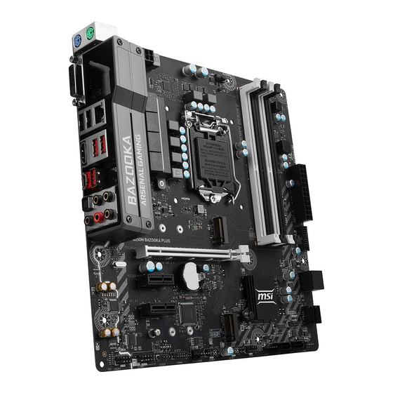
Unpacking
Thank you for buying the MSI
B250M BAZOOKA PLUS/ B250M BAZOOKA OPT BOOST
®
motherboard. Check to make sure your motherboard box contains the following items.
If something is missing, contact your dealer as soon as possible.
Drivers & Utilities
Motherboard User
Disc
Motherboard
Guide
B250M BAZOOKA OPT
BOOST with pre-
installed Intel
Optane™
®
Memory module
I/O Shield
SATA Cable x2
1
Unpacking
Advertisement
Table of Contents

Related Manuals for MSI B250M BAZOOKA PLUS


Summary of Contents for MSI B250M BAZOOKA PLUS
-
Page 1: Unpacking
Unpacking Thank you for buying the MSI B250M BAZOOKA PLUS/ B250M BAZOOKA OPT BOOST ® motherboard. Check to make sure your motherboard box contains the following items. If something is missing, contact your dealer as soon as possible. Drivers & Utilities... -
Page 2: Safety Information
Safety Information The components included in this package are prone to damage from electrostatic discharge (ESD). Please adhere to the following instructions to ensure successful computer assembly. Ensure that all components are securely connected. Loose connections may cause the computer to not recognize a component or fail to start. Hold the motherboard by the edges to avoid touching sensitive components. -
Page 3: Quick Start
Quick Start Preparing Tools and Components Intel LGA 1151 CPU ® CPU Fan Thermal Paste DDR4 Memory Power Supply Unit Chassis SATA Hard Disk Drive Graphics Card SATA DVD Drive A Package of Screws Phillips Screwdriver Quick Start... -
Page 4: Installing A Processor
Installing a Processor http://youtu.be/bf5La099urI Quick Start... -
Page 5: Installing Ddr4 Memory
Installing DDR4 memory http://youtu.be/T03aDrJPyQs DIMMB2 DIMMB2 DIMMB1 DIMMA2 DIMMA2 DIMMA2 DIMMA1 Quick Start... -
Page 6: Connecting The Front Panel Header
Connecting the Front Panel Header http://youtu.be/DPELIdVNZUI HDD LED + Power LED + HDD LED - Power LED - Reset Switch Power Switch Reset Switch Power Switch JFP1 Reserved No Pin JFP1 HDD LED - HDD LED HDD LED + POWER LED - POWER LED POWER LED + Quick Start... -
Page 7: Installing The Motherboard
Installing the Motherboard Quick Start... -
Page 8: Installing Sata Drives
Installing SATA Drives http://youtu.be/RZsMpqxythc Quick Start... -
Page 9: Installing A Graphics Card
Installing a Graphics Card http://youtu.be/mG0GZpr9w_A Quick Start... -
Page 10: Connecting Peripheral Devices
Connecting Peripheral Devices Quick Start... -
Page 11: Connecting The Power Connectors
Connecting the Power Connectors http://youtu.be/gkDYyR_83I4 ATX_PWR1 CPU_PWR1 Quick Start... -
Page 12: Power On
Power On Quick Start... -
Page 13: Table Of Contents
Contents Unpacking ......................1 Safety Information ....................2 Quick Start ......................3 Preparing Tools and Components ................3 Installing a Processor ..................... 4 Installing DDR4 memory ..................5 Connecting the Front Panel Header ............... 6 Installing the Motherboard ..................7 Installing SATA Drives..................... - Page 14 Installing Utilities ....................57 LIVE UPDATE 6 ...................... 58 COMMAND CENTER ..................... 60 GAMING APP ......................64 X-BOOST ....................... 69 MSI SMART TOOL ....................71 DRAGON EYE ......................72 RAMDISK....................... 73 GAMING LAN MANAGER ..................74 Intel Extreme Tuning Utility ................76 ®...
-
Page 15: Specifications
Supports Intel Extreme Memory Profile (XMP)** * Please refer www.msi.com for more information on compatible memory. ** DDR4 memory modules can only run at maximum of 2400 MHz for 7th Gen processors and 2133 MHz for 6th Gen processors on XMP mode. - Page 16 Continued from previous page ® 1x Realtek 8111H Gigabit LAN controller 1x PS/2 keyboard port 1x PS/2 mouse port 1x HDMI™ port 1x DVI-D port 1x LAN (RJ45) port Back Panel Connectors 2x USB 2.0 Type-A ports 3x USB 3.1 Gen1 Type-A ports 1x USB 3.1 Gen1 Type-C port 5x OFC audio jacks 1x Optical S/PDIF OUT connector...
- Page 17 Drivers COMMAND CENTER LIVE UPDATE 6 FAST BOOT SUPER CHARGER GAMING APP RAMDISK GAMING LAN MANAGER X-BOOST Software MSI SMART TOOL Intel Extreme Tuning Utility ® Norton Internet Security Solution ™ Google Chrome ,Google Toolbar, Google Drive ™ SteelSeries Engine 3...
- Page 18 RAMDisk GAMING HOTKEY Mystic light SYNC WTFast GPN* 2-Month Premium License ƒ Multi-Server Network Optimization ƒ Advanced Lag Spike & Disconnect Reduction ƒ * This offer is valid for a limited period only, for more information please visit www.msi.com Specifications...
-
Page 19: Block Diagram
Block Diagram HDMI HDMI DVI-D Dual Channel DDR4 Memory PCI Express Bus DMI 3.0 2 x M.2 Switch PCIe x1 slot SATA 6Gb/s PCIe x1 slot B250 USB 3.1 Gen1 Realtek 8111H USB 2.0 LPC Bus Realtek NV6795 ALC892 Super I/O P/S2 Mouse / Keyboard Audio Jacks Block Diagram... -
Page 20: Rear I/O Panel
Rear I/O Panel USB 3.1 Gen1 Audio Ports Type-A PS/2 Mouse DVI-D Optical S/PDIF-Out PS/2 Keyboard USB 2.0 USB 3.1 Gen1 Type-C LAN Port LED Status Table Link/ Activity LED Speed LED Status Description Status Description No link 10 Mbps connection Yellow Linked Green... -
Page 21: Realtek Hd Audio Manager
Realtek HD Audio Manager After installing the Realtek HD Audio driver, the Realtek HD Audio Manager icon will appear in the system tray. Double click on the icon to launch. Device Selection Advanced Settings Jack Status Application Enhancement Main Volume Connector Strings Profiles... -
Page 22: Overview Of Components
Overview of Components DIMMA2 DIMMA1 DIMMB1 DIMMB2 CPU_FAN1 CPU_PWR1 CPU Socket EZ Debug LED ATX_PWR1 SYS_FAN3 M2_1 JUSB1 PCI_E1 JBAT1 PCI_E2 SATA▼1▲2 JCI1 PCI_E3 SATA3 M2_2* SATA4 JCOM1 SYS_FAN1 JAUD1 JLED1 SATA5 SYS_FAN2 SATA6 JTPM1 JUSB3 JFP2 JUSB2 JFP1 *B250M BAZOOKA OPT BOOST with pre-installed Intel Optane™... - Page 23 Component Contents Port Name Port Type Page CPU_FAN1,SYS_FAN1~3 Fan Connectors CPU_PWR1, ATX_PWR1 Power Connectors CPU Socket LGA1151 CPU Socket DIMMA1, DIMMA2, DIMM Slots DIMMB1,DIMMB2 JAUD1 Front Audio Connector JBAT1 Clear CMOS (Reset BIOS) Jumper JCI1 Chassis Intrusion Connector JCOM1 Serial Port Connector JFP1, JFP2 Front Panel Connectors JLED1...
-
Page 24: Cpu Socket
Always unplug the power cord from the power outlet before installing or removing the CPU. Please retain the CPU protective cap after installing the processor. MSI will deal with Return Merchandise Authorization (RMA) requests if only the motherboard comes with the protective cap on the CPU socket. -
Page 25: Dimm Slots
DIMM Slots DIMMA1 DIMMB1 Channel A Channel B DIMMA2 DIMMB2 Memory module installation recommendation DIMMB2 DIMMB2 DIMMB1 DIMMA2 DIMMA2 DIMMA2 DIMMA1 Important Always insert memory modules in the DIMMA2 slot first. Due to chipset resource usage, the available capacity of memory will be a little less than the amount of installed. -
Page 26: Pci_E1~3: Pcie Expansion Slots
If you install a large and heavy graphics card, you need to use a tool such as MSI Gaming Series Graphics Card Bolster to support its weight to prevent deformation of the slot. - Page 27 M.2 , SATA & PCIe combination table Slot Available SATA connectors & PCIe slots M2_1 PCIe SATA PCIe SATA M2_2 PCIe PCIe SATA SATA ✓ ─ ✓ ─ SATA1 ✓ ✓ ✓ ✓ SATA2 ✓ ✓ ✓ ✓ SATA3 ✓ ✓...
-
Page 28: M2_1: M.2 Slot (Key M)
M2_1: M.2 Slot (Key M) Important Intel RST only supports PCIe M.2 SSD with UEFI ROM, ® does not support Legacy ROM. The SATA1/SATA5 port will be unavailable when an M.2 SATA SSD module has been installed in the M2_1/M2_2 slot. -
Page 29: Jfp1, Jfp2: Front Panel Connectors
JFP1, JFP2: Front Panel Connectors These connectors connect to the switches and LEDs on the front panel. JFP1 HDD LED + Power LED + HDD LED - Power LED - Reset Switch Power Switch Reset Switch Power Switch Reserved No Pin Speaker - Buzzer + JFP2... -
Page 30: Cpu_Pwr1, Atx_Pwr1: Power Connectors
CPU_PWR1, ATX_PWR1: Power Connectors These connectors allow you to connect an ATX power supply. CPU_PWR1 Ground +12V Ground +12V Ground +12V Ground +12V +3.3V +3.3V +3.3V -12V Ground Ground PS-ON# Ground Ground Ground ATX_PWR1 Ground Ground PWR OK 5VSB +12V +12V +3.3V Ground... -
Page 31: Jusb2~3: Usb 2.0 Connectors
JUSB2~3: USB 2.0 Connectors These connectors allow you to connect USB 2.0 ports on the front panel. USB0- USB1- USB0+ USB1+ Ground Ground No Pin Important Note that the VCC and Ground pins must be connected correctly to avoid possible damage. -
Page 32: Cpu_Fan1,Sys_Fan1~3: Fan Connectors
CPU_FAN1,SYS_FAN1~3: Fan Connectors Fan connectors can be classified as PWM (Pulse Width Modulation) Mode or DC Mode. PWM Mode fan connectors provide constant 12V output and adjust fan speed with speed control signal. DC Mode fan connectors control fan speed by changing voltage. When you plug a 3-pin (Non-PWM) fan to a fan connector in PWM mode, the fan speed will always maintain at 100%, which might create a lot of noise. -
Page 33: Jci1: Chassis Intrusion Connector
JCI1: Chassis Intrusion Connector This connector allows you to connect the chassis intrusion switch cable. Normal Trigger the chassis intrusion event (default) Using chassis intrusion detector Connect the JCI1 connector to the chassis intrusion switch/ sensor on the chassis. Close the chassis cover. Go to BIOS >... -
Page 34: Jled1: Rgb Led Connector
JLED1: RGB LED connector These connectors allow you to connect the 5050 RGB LED strips. +12V 5050 LED strip Extension cable JLED1 Important This connector supports 5050 RGB multi-color LED strips (12V/G/R/B) with the maximum power rating of 3A (12V). Please keeping the LED strip shorter than 2 meters to prevent dimming. -
Page 35: Ez Debug Led
EZ Debug LED These LEDs indicate the debug status of the motherboard. CPU - indicates CPU is not detected or fail. DRAM - indicates DRAM is not detected or fail. VGA - indicates GPU is not detected or fail. BOOT - indicates the booting device is not detected or fail. -
Page 36: Bios Setup
Press Delete key, when the Press DEL key to enter Setup Menu, F11 to enter Boot Menu message appears on the screen during the boot process. Use MSI FAST BOOT application. Click on GO2BIOS button and choose OK. The system will reboot and enter BIOS setup directly. -
Page 37: Resetting Bios
Updating BIOS Updating BIOS with M-FLASH Before updating: Please download the latest BIOS file that matches your motherboard model from MSI website. And then save the BIOS file into the USB flash drive. Updating BIOS: Press Del key to enter the BIOS Setup during POST. -
Page 38: System Status Menu
System Status Menu After entering BIOS, the following screen is displayed. The System Status Menu allows you to configure basic system settings, such as time, date etc. System Language [English] Allows you to select the language of BIOS setup. System Date Sets the system date. -
Page 39: Advanced Menu
Advanced Menu The Advanced Menu allows you to set up the items of special enhanced features. PCI Subsystem Settings Sets PCI, PCI express interface protocol and latency timer. Press Enter to enter the sub-menu. fPEG X - Max Link Speed [Auto] Sets PCI Express protocol of PCIe x16 slots for matching different installed devices. - Page 40 Network Stack is enabled. [Enabled] Enables the Ipv6 PXE boot support. [Disabled] Disables the Ipv6 PXE boot support. fSATA Mode [AHCI mode] - B250M BAZOOKA PLUS, [Optane mode] -B250M BAZOOKA OPT BOOST Sets the operation mode of the onboard SATA controller.
- Page 41 fHPET [Enabled] Enables or disables the HPET (High Precision Event Timers) support. Integrated Graphics Configuration Adjusts integrated graphics settings for optimum system. Press Enter to enter the sub-menu. fInitiate Graphic Adapter [PEG] Selects a graphics device as the primary boot device. [IGD] Integrated Graphics Display.
- Page 42 fSerial (COM) Port x Settings [Auto] Sets serial port x (COM). If set to Auto, BIOS will optimize the IRQ automatically or you can set it manually. Hardware Monitor Sets fan speeds. Press <Enter> to enter the sub-menu. fCPU/ SYS FanX Smart Fan Control [Enabled] Enables or disables the smart fan control.
- Page 43 Disables this function. fMSI Fast Boot [Disabled] MSI Fast Boot is the fastest way to boot the system. It will disable more devices to speed up system boot time which is faster than the boot time of Fast Boot. [Enabled] Enables the MSI Fast Boot function to speed up booting time.
- Page 44 fSecure Boot Sets the Windows secure boot to prevent the unauthorized accessing. Press Enter to enter the sub-menu. This sub-menu will appear when Windows 8.1/ 10 WHQL Support is enabled. fSecure Boot Support [Disabled] Enables or disables secure boot support. [Enabled] Enables the secure boot function and allow you to set the secure boot settings.
- Page 45 fResume by USB Device [Disabled] Enables or disables the system wake up by USB devices. [Enabled] Enables the system to be awakened from sleep state when activity of USB device is detected. [Disabled] Disables this function. fResume From S3/S4/S5 by PS/2 Mouse [Disabled] Enables or disables the system wake up by PS/2 mouse.
-
Page 46: Overclocking Menu
Overclocking Menu The Overclocking Menu allows you to adjust the frequency and voltage. Increasing the frequency may get better performance. Important Overclocking your PC manually is only recommended for advanced users. Overclocking is not guaranteed, and if done improperly, it could void your warranty or severely damage your hardware. - Page 47 Adjusted CPU Frequency Shows the adjusted CPU frequency. Read-only. CPU Ratio Offset When Running AVX [Auto]* Sets a offset value to lower the CPU core ratio. It could be helpful for heat dissipation when running AVX instruction set. If set to Auto, BIOS will configure this setting automatically.
- Page 48 DRAM Reference Clock [Auto]* Sets the DRAM reference clock. The valid value range depends on the installed CPU. This item appears when a CPU that supports this adjustment is installed. DRAM Frequency [Auto] Sets the DRAM frequency. Please note the overclocking behavior is not guaranteed. Adjusted DRAM Frequency Shows the adjusted DRAM frequency.
- Page 49 fCPU Technology Support Press <Enter> to enter the sub-menu. The sub-menu shows the key features of installed CPU. Read only. MEMORY-Z Press <Enter> to enter the sub-menu. This sub-menu displays all the settings and timings of installed memory. You can also access this information menu at any time by pressing [F5].
- Page 50 fAdjacent Cache Line Prefetch [Enabled] Enables or disables the CPU hardware prefetcher (MLC Spatial prefetcher). [Enabled] Enables adjacent cache line prefetching for reducing the cache latency time and tuning the performance to the specific application. [Disabled] Enables the requested cache line only. fCPU AES Instructions [Enabled] Enables or disables the CPU AES (Advanced Encryption Standard-New Instructions) support.
- Page 51 fIntel Turbo Boost [Enabled] Enables or disables the Intel Turbo Boost. This item is for Normal mode and ® appears when a CPU that support Turbo Boost is installed. [Enabled] Enables this function to boost CPU performance automatically over specification when system request the highest performance state. [Disabled] Disables this function.
-
Page 52: M-Flash Menu
M-Flash Menu The M-Flash Menu allows you to update BIOS with a USB flash disk. Select one file to update BIOS and ME Selects a BIOS file, includes the ME management settings, in the USB flash drive to update the BIOS and ME. The system will reboot after updating. BIOS Setup... -
Page 53: Security Menu
Security Menu The Security Menu allows you to set supervisor and user passwords. Administrator Password Sets administrator password for system security. User has full rights to change the BIOS items with administrator password. After setting the administrator password, the state of this item will show “Installed” . User Password Sets User Password for system security. - Page 54 Trusted Computing Sets TPM (Trusted Platform Module) function. fSecurity Device Support [Disabled] Enables or disables the TPM function to build the endorsement key for accessing the system. fTPM Device Selection [PTT] Selects TPM device: PTT or dTPM. [PTT] Select it for Intel Platform Trust technology [dTPM] Select it for installed TPM device.
-
Page 55: Boot Menu
Boot Menu The Boot Menu allows you to specify the priority of boot devices. Full Screen Logo Display [Enabled] Enables or disables to show the full screen logo while system POST. [Enabled] Shows the logo in full screen. [Disabled] Shows the POST messages. GO2BIOS [Disabled] Allows system to enter BIOS setup directly by pressing the Power button for 4 sec upon bootup. -
Page 56: Save & Exit Menu
Save & Exit Menu This menu allows you to load the BIOS default values or factory default settings into the BIOS and exit the BIOS setup utility with or without changes. Discard Changes and Exit Exit BIOS setup without saving any change. Save Changes and Reboot Save all changes and reboot the system. -
Page 57: Software Description
7/ 8.1/ 10 disc into your optical drive. ® Note: Due to chipset limitation, during the Windows 7 installation process, USB optical drives or USB flash drives are not supported. You can use MSI Smart Tool to install Windows ®... -
Page 58: Live Update 6
® drivers, BIOS and utilities. With LIVE UPDATE 6, you do not need to search the drivers on specific MSI web page. LIVE UPDATE 6 will download the appropriate drivers automatically. Download Options... -
Page 59: Total Installer
Select the Live Update tab. Choose Automatic scan, system will automatically scan all the items and search for the latest update files. Or you can choose Manual scan and select the items you wish to scan. Click the Scan button at the bottom. It may take several minutes to complete the process. -
Page 60: Command Center
COMMAND CENTER COMMAND CENTER is an user-friendly software and exclusively developed by MSI, helping users to adjust system settings and monitor status under OS. With the help of COMMAND CENTER, making it possible to achieve easier and efficient monitoring process and adjustments than that under BIOS. In addition, the COMMAND CENTER can be a server for mobile remote control application. - Page 61 CPU Fan CPU Fan control panel provides Smart mode and Manual Mode. You can switch the control mode by clicking the Smart Mode and Manual Mode buttons on the top of the CPU Fan control panel. Manual Mode - allows you to manually control the CPU fan speed by percentage.
- Page 62 GAME BOOST GAME BOOST provides a specified CPU frequency for overclocking the CPU. Option Buttons - Advanced When click the Advanced button, The Voltage, Fan and DRAM icons will appear. Voltage - allows you to adjust advanced voltage values of CPU and chipset. Fan - allows you to control the system fans speed.
- Page 63 Find the IP address on the SoftAP Management Setting area, and enter the IP address on your MSI COMMAND CENTER APP to link your system. ® Press Refresh on the MSI COMMAND CENTER APP to verify that monitoring and ® OC functions are working properly.
-
Page 64: Gaming App
Connect your android device and motherboard to the same local area network. Run MSI GAMING APP APP on your android device. ® Press the Remote Control Setting icon on the MSI GAMING APP APP to find the ® paired device Name you set in the Remote Control Setting panel. - Page 65 LED function allows you to control LED lights on your motherboard. ON/OFF LED Area Selection LED ON/OFF - allows you to turn ON/ OFF the LED function. LED Area Selection - separately controls each segment of LEDs on your motherboard and graphics cards. MB Extend LED (optional, for RGB multi-color LED connector)- controls the ƒ...
- Page 66 Eye Rest Eye Rest allows you to optimize the display on your monitor. EyeRest - reduces blue-light of your LED backlit screen, in order to protect your eyes. Gaming - automatically increases contrast ratio of your screen. Movie - automatically increases dynamic contrast ratio of your screen. Customize - allows you to adjust gamma, contrast and color balance for your screen.
- Page 67 Login Keys - provides hotkey login function. ƒ MSI Smart Keys - allows you to define hotkeys for MSI Smart Keys. ƒ Hotkey Manager - allows you to create, edit and delete hotkeys. Current Hotkeys - shows all existing hotkeys.
- Page 68 Mouse Master Mouse Master provides mouse macro function. You can also use it to change DPI of your mouse. DPI Setting Delay Time Default Button Macro Hot Key DPI Hot Key Mouse Action Action List Test Area Edit Buttons Clear Button Load Button Save Button Delay Time - allows you to apply a delay time in mouse macro.
-
Page 69: X-Boost
X-BOOST The MSI X-BOOST allows you to select the system performance mode to meet your current system environment or supports faster storage access speed. Most of the external storage and memory cards can also benefit this feature. Easy In Easy page, you can select one system performance mode to meet the current system environment. - Page 70 OPTANE BOOST - supports faster access speed of Intel Optane memory (require a reboot). Important Please note that you can only select one mode at a time from Easy or Advance page as MSI X-BOOST function. The improved transfer rate/ access speed will vary with the USB/ storage device. Software Description...
-
Page 71: Msi Smart Tool
MSI SMART TOOL is a convenient tool that can help you to create your Windows installation USB flash drive with USB 3.0 drivers. Main menu After installing and activating MSI SMART TOOL, it will display a main menu for you to choose Win7 Smart Tool. WIN7 SMART TOOL Before you can create your Windows installation USB flash drive, you’... -
Page 72: Dragon Eye
DRAGON EYE DRAGON EYE is an application allows you to watch a game guide, tutorial, live match or tournament stream while playing a game. In the game, you can use hotkeys to control / adjust the window of video. Size Settings Position Settings On / Off Switch Help... -
Page 73: Ramdisk
RAMDISK RAMDISK creates a virtual RAM drive using the available memory in your computer, the performance of the RAMDISK is faster than an SSD and hard drive. RAMDISK allows you to store any temporary information on it. Furthermore, using the RAMDISK will extend your SSD’... -
Page 74: Gaming Lan Manager
GAMING LAN MANAGER GAMING LAN MANAGER is an utility for traffic shaping for the Windows 7/ 8.1/ 10. It can keep your internet fast during heavy upload/ download and improve your ping for online games. If your motherboard has a Wi-Fi module, GAMING LAN MANAGER provides virtual access point function for traffic shaping for your mobile devices. - Page 75 Speed Testing The speed testing is used to optimize bandwidth usage. To test the Upload and Down- load speed, please follow the steps below: Click the Network Test block in GAMING LAN MANAGER. Click Test Network Speed button. The test takes several minutes to test your network speed.
-
Page 76: Intel ® Extreme Tuning Utility
Intel Extreme Tuning Utility ® Intel Extreme Tuning Utility (Intel XTU) is a simple overclocking software for you to ® tune, test and monitor your system. Tuning Controls Views Settings Help System Navigation Table System System Monitors Graphs Views Settings Help Views - toggles to switche between Monitoring and Show All view. -
Page 77: Steelseries Engine 3
SteelSeries Engine 3 SteelSeries Engine 3 is a unified platform built to support all of SteelSeries products. It can deploy your saved device settings automatically when switching between your favorite games or applications. After installation the SteelSeries Engine background processes will start and the interface will open automatically. - Page 78 Configuring Your Devices You can custom configurations for SteelSeries devices in their Configuration Windows. The top left displays the name of the configuration you are viewing, the body features widgets for customizing various functions of the device, and at the bottom are Save/ Revert buttons, a Live Preview toggle, and a button to open/close the collapsible Configuration List Panel.
-
Page 79: Cpu-Z
CPU-Z CPU-Z is an utility that gathers information on some of the main devices of your system. CPU Tab - shows processor name, code name, package, specification, instructions sets, core speed and cache levels. Caches Tab - shows extended information related to the cache capabilities. Mainboard Tab - shows motherboard manufacturer, model name, chipset, BIOS version and graphic interface. -
Page 80: Tridef Vr
TriDef VR With TriDef VR you can play your favorite PC games on a huge 3D screen inside your virtual reality headset. It is compatible with the Oculus Rift and HTC Vive. After installation, please ensure that your VR headset is set up and working correctly, then double-click TriDef VR Games on the Desktop, or from: Start >... - Page 81 Games Tab The first tab you’ ll see on the main window is the Games tab. As mentioned, apps or games launched from the desktop will appear in 2D on the virtual screen. However, if you launch a supported game from the Games tab, it will be displayed on the virtual screen in stereoscopic 3D! The first time you launch TriDef VR, the application will scan your PC and automatically add supported games to the list.
- Page 82 Settings Popup Look at the Settings item for 1 second to display the Settings popup. This popup window appears in front of the virtual screen. Use your mouse to adjust the slider values. Screen Settings - adjust the virtual screen’ s size, distance and curvature. Game Settings - adjust 3D settings for that game.
-
Page 83: Tridef Smartcam
TriDef SmartCam Use TriDef SmartCam to replace or SmartBlur your background in video chat applications or to remove your background in XSplit. Just select TriDef SmartCam wherever you see a list of cameras or choose your webcam application. The following description uses XSplit Gamecaster for an example. TriDef SmartCam for XSplit Gamecaster After installation TriDef SmartCam is integrated into XSplit Gamecaster version 2.5 and newer. -
Page 84: Intel ® Optane™ Memory Configuration
Optane™ memory can accelerate the Windows 10 64bit operating system. This ® section describes how to install and remove the Intel Optane™ memory. ® System Requirements Intel Optane™ memory ready MSI motherboards ® ® Supported 7th Gen, or later, Intel Core™ - i Processor ®... - Page 85 Enable Intel Optane™ Memory. ® • Enable Intel Optane™ Memory via the Intel Optane™ memory application ® ® (auto-launches upon reboot). • Click Yes in the dialog. • Reboot System. WARNING Once you enable Intel Optane™ memory, in order to prevent seriously damage your ®...
-
Page 86: Removing The Intel ® Optane™ Memory
Removing the Intel Optane™ memory ® If you no longer want to use Intel Optane™ memory, you have to disable the Intel ® ® Optane™ memory before removing the Intel Optane™ memory module to avoid ® operating system damage. Please follow the steps below to remove the Intel Optane™... -
Page 87: Troubleshooting
Troubleshooting Lost BIOS password Before sending the motherboard for RMA repair, try to go over troubleshooting Clear the CMOS, but that will cause guide first to see if your got similar you to lose all customized settings in symptoms as mentioned below. the BIOS. -
Page 88: Regulatory Notices
EU REACH Regulation (Regulation EC No. 1907/2006 of the European Parliament and the This device complies with part 15 of the FCC Rules. Council), MSI provides the information of chemical Operation is subject to the following two conditions: substances in products at: (1) This device may not cause harmful interference, and http://www.msi.com/html/popup/csr/evmtprtt_pcm. - Page 89 MSI will comply with the product take entregar a una empresa autorizada para la recogida de back requirements at the end of life of MSI-branded estos residuos.
- Page 90 MSI si adeguerà a tale Direttiva ritirando tutti i prodotti marchiati MSI che sono stati venduti all’interno dell’Unione Europea alla fine del loro ciclo di vita.
- Page 91 Alternatively, please try the following help resources for further guidance. y Visit the MSI website for technical guide, BIOS updates, driver updates, and other information: http://www.msi.com y Register your product at: http://register.msi.com...