Carrier PERFORMANCE 50VT-A Installation Instructions Manual
Single-packaged heat pump system with puron (r-410a) refrigerant single and three phase
Hide thumbs
Also See for PERFORMANCE 50VT-A:
- Owner's information manual (6 pages) ,
- Owner's information manual (4 pages) ,
- Installation instructions manual (50 pages)
Table of Contents
Advertisement
50VT ---A
Performancet 14 SEER Single ---Packaged Heat Pump
System with Puron® (R ---410A) Refrigerant
Single and Three Phase
2---5 Nominal Tons (Sizes 24---60)
NOTE:
Read the entire instruction manual before starting the
installation.
NOTE:
Installer: Make sure the Owner's Manual and Service
Instructions are left with the unit after installation.
TABLE OF CONTENTS
. . . . . . . . . . . . . . . . . . . . . . . . . . . . . . . . . . .
. . . . . . . . . . . . . . . . . . . . . . . . . . . . . . . . . .
. . . . . . . . . . . . . . . . . . . . . . . . . . . . . . . . . . . .
. . . . . . . . . . . . . . . . . . . . . . . . . . . . . . . . .
. . . . . . . . . . . . . . . . . . . . . . . . . . . . . . .
. . . . . . . . . . . . . . . . . . . . . . . . . . . . . . . . . . . . . .
. . . . . . . . . . . . . . . . . . . . . . . . . . . . . . . . . . . . .
. . . . . . . . . . . . . . . . . . . . . . . . . . . . . . . . .
. . . . . . . . . . . . . . . . . . . . . . . . . . . . . . . . .
. . . . . . . . . . . . . . . . . . . . . . . . . . . . . . . . . . . . . .
. . . . . . . . . . . . . . . . . . . . . . . . . . . .
. . . . . . . . . . . . . . . . . . . . . . . . . . . . .
. . . . . . . . . . . . . . . . . . . . . . . . . . . .
. . . . . . . . . . . . . . . . . . . . . . . . . . . .
. . . . . . . . . . . . . . . . . . . . . . . . . . . . . . . . . . .
. . . . . . . . . . . . . . . . . . . . . . . . . . . . . . . . . . . . .
. . . . . . . . . . . . . . . . . . . . . . . . . . . . .
. . . . . . . . . . . . . . . . . . . . . . . . . . . . . . . . . . .
. . . . . . . . . . . . . . . . . . . . . . . . . . . . . . . . . . . . .
. . . . . . . . . . . . . . . . . . . . . . . . . . . . . . . . . . . . . . .
. . . . . . . . . . . . . . . . . . . . . . . . . . . . . . . .
. . . . . . . . . . . . . . . . . . . . . . . . . . . . . . . . . . . . . . . .
. . . . . . . . . . . . . . . . . . . . . . . . . . .
. . . . . . . . . . . . . . . . . . . . . . . . . . . . . . . . . . . . .
. . . . . . . . . . . . . . . . . . . . . . . . . . . . . . . . .
. . . . . . . . . . . . . . . . . . . . . . . . . . . . . . . . . . .
. . . . . . . . . . . . . . . . . . . . . . . . . . . . . . . . .
. . . . . . . . . . . . . . . . . . . . . . . . . . . . .
. . . . . . . . . . . . . . . . . . . . . . . . . . . . . .
Installation Instructions
. . . . . . . . . . . . . . . . . . . . . . . . .
. . . . . . . . . . . . . . . . . .
. . . . . . . . . . . . . . . . . . . . . . . . . . .
. . . . . . . . . . . . . . . . . . . . . . . . . .
. . . . . . . . . . . . . . . . . . . . . .
. . . . . . . . . . . . . . . . . . . . . . . . .
. . . . . . . . . . . . . . . . . . . . . . . . .
. . . . . . . . . . . . . . .
. . . . . . . . . . . . . . . . . . . . . . . .
. . . . . . . . . . . . . . . . .
. . . . . . . .
. . . . . . . . . . . . . . . . . . . . . . . . .
. . . . . . . . . . . .
. . . . . . . . . . . . . .
. . . . . . . . . . . . . . . . . . . . . . . .
. . . . . .
. . . . . . . . . . . . . . . . . . . . . . .
. . . . . . . . . . . . . . . . . . . .
PAGE
1
2
2- -9
2
2
2
2
2
2
2
6
6
6
7
7
8
8
8
9
9
9
9
9
9
17
17- -20
17
17
SAFETY CONSIDERATIONS
17
18
Installation and servicing of this equipment can be hazardous due
18
to mechanical and electrical components. Only trained and
19
qualified personnel should install, repair, or service this equipment.
20
Untrained personnel can perform basic maintenance functions such
20
as cleaning and replacing air filters. All other operations must be
20
performed by trained service personnel. When working on this
23- -28
equipment, observe precautions in the literature, on tags, and on
23
labels attached to or shipped with the unit and other safety
23
precautions that may apply.
26
Follow all safety codes. Wear safety glasses, protective clothing,
26
and work gloves. Use quenching cloth for brazing operations.
26
Have a fire extinguisher available. Read these instructions
26
thoroughly and follow all warnings or cautions included in
26
literature and attached to the unit. Consult local building codes, the
26
current editions of the National Electrical Code (NEC) NFPA 70.
27
In Canada refer to the current editions of the Canadian Electrical
27
Code CSA C22.1.
27
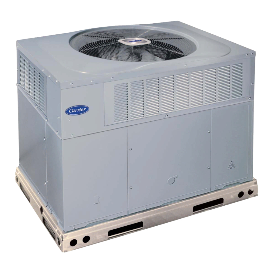
1
Fig. 1 - - Unit 50VT- -A
. . . . . . . . . . . . . . . . . . . . . . . . . . . . . . . .
. . . . . . . . . . . . . . . . . . . . . . . . . . . . . . . . . . . .
. . . . . . . . . . . . . . . . . . . . . . . . . . . . . . . . .
. . . . . . . . . . . . . . . . . . . . . . . . . . .
. . . . . . . . . . . . .
. . . . . . . . . . . . . . . . . . . . . . . . . . . . . . . .
. . . . . . . . . . . . . . . . . . . . . . . . . . . .
. . . . . . . . . . . . . . . . . . . . . . . . .
. . . . . . . . . . . . . . . . . . . . . . . . . . . . . .
. . . . . . . . . . . . . . . . . . . . . . . . . . . .
A09033
. . . . . . . . .
27
27
27
27
. . . .
27
27
28
28
28
28
28
28
Advertisement
Table of Contents

Related Manuals for Carrier PERFORMANCE 50VT-A


Summary of Contents for Carrier PERFORMANCE 50VT-A
-
Page 1: Table Of Contents
50VT ---A Performancet 14 SEER Single ---Packaged Heat Pump System with Puron® (R ---410A) Refrigerant Single and Three Phase 2---5 Nominal Tons (Sizes 24---60) Installation Instructions NOTE: Read the entire instruction manual before starting the installation. NOTE: Installer: Make sure the Owner’s Manual and Service Instructions are left with the unit after installation. -
Page 2: Introduction
INTRODUCTION The 50VT- -A heat pump is fully self- -contained and designed for outdoor installation. (See Fig. 1) Standard units are shipped in a horizontal- -discharge configuration for installation on a ground level slab. - Page 3 A09410 Fig. 2 - - 50VT- -A24- -30 Unit Dimensions...
- Page 4 A09411 Fig. 3 - - 50VT- -A36- -60 Unit Dimensions...
-
Page 5: Roof Curb Dimensions
HVAC unit HVAC unit basepan base rails Anchor screw Flashing field supplied Roofing material field supplied Cant strip field supplied *Provided with roofcurb ROOF CURB DETAIL LARGE CURB UNIT CATALOG SIZE NUMBER (mm) Small CPRFCURB010A00 11 (279) CPRFCURB011A00 14 (356) Large CPRFCURB012A00 11 (279) -
Page 6: Rig And Place Unit
CAUTION - NOTICE TO RIGGERS PRUDENCE - AVIS AUX MANIPULATEUR ACCESS PANELS MUST BE IN PLACE WHEN RIGGING. PANNEAUX D'ACCES DOIT ÊTRE EN PLACE POUR MANIPULATION. Use top skid as spreader bar. / Utiliser la palette du haut comme barre de répartition SEE DETAIL A VOIR DÉTAIL A RIGGING WEIGHTS (SMALL CABINET) -
Page 7: Select And Install Ductwork
Step 5 — Select and Install Ductwork The design and installation of the duct system must be in accordance with the standards of the NFPA for installation of non- -residence type air conditioning and ventilating systems, NFPA 90A or residence- -type, NFPA 90B and/or local codes and ordinances. -
Page 8: Provide For Condensate Disposal
screwed or bolted to duct flanges. Use suitable gaskets to ensure weather- -tight and airtight seal. 4. All units must have field- -supplied filters or accessory filter rack installed in the return- -air side of the unit. Recommended sizes for filters are shown in Table 1. 5. -
Page 9: Special Procedures For 208- -V Operation
G. There are no on or off delays. d. HEAT PUMP HEATING MODE (1.) Thermostat closes circuits R to G and R to Y. The e. HEAT PUMP HEATING WITH AUXILIARY ELECTRIC HEAT (1.) Thermostat closes circuits R to G, R to Y and R to f. - Page 10 Unit Size Shipping Weight (lb) (kg) Compressor Quantity Type Refrigerant Refrigerant Quantity (lb) Quantity (kg) Refrigerant Metering Device Orifice OD (in) (mm) Outdoor Coil Rows...Fins/in, face area (sq. ft.) Outdoor Fan Nominal Airflow (cfm) Diameter (in.) Diameter (mm) Motor hp (rpm) Indoor Coil Rows...Fins/in, face area (sq.
- Page 11 A11002 Fig. 12 - - Connection Wiring Schematics 208/230- -1- -60...
- Page 12 A11001 Fig. 12 Cont. - - Ladder Wiring Schematics 208/230- -1- -60...
- Page 13 A11006 Fig. 13 - - Connection Wiring Schematics - - 208/230- -3- -60...
- Page 14 A11005 Fig. 13 Cont. - - Ladder Wiring Schematics - - 208/230- -3- -60...
- Page 15 A10195 Fig. 14 - - Connection Wiring Diagram 460- -3- -60...
-
Page 16: Ladder Wiring Diagram
A10195 Fig. 14 Cont. - - Ladder Wiring Diagram 460- -3- -60... -
Page 17: Pre- -Start- -Up
5 minutes have elapsed. The defrost board has a built- -in 5 minute delay between cycles. The 5 minute compressor delay also applies to heat pump heating mode. Step 1 — Check for Refrigerant Leaks... -
Page 18: Checking & Adjusting Refrigerant Charge
turning backwards, the difference between compressor suction and discharge pressures may be near zero. Checking and Adjusting Refrigerant Charge The refrigerant system is fully charged with Puron (R- -410A) refrigerant and is tested and factory sealed. NOTE: Adjustment of the refrigerant charge is not required unless the unit is suspected of not having the proper Puron (R- -410A) charge. -
Page 19: Continuous Fan Operation
LCS – Loss of Charge Switch Accurater ® Metering De vice Arrow indicates direction of flo w Fig. 15 - - Typical Heat Pump Operation, Cooling Mode CAUTION UNIT OPERATION HAZARD Failure to follow this caution may result in unit component damage or improper operation. -
Page 20: Defrost Control
Accurater ® Metering De vice Arrow indicates direction of flo w Fig. 17 - - Typical Heat Pump Operation, Heating Mode Step 3 — Defrost Control Quiet Shift Quiet Shift is a field- -selectable defrost mode, which will eliminate occasional noise that could be heard at the start of defrost cycle and restarting of heating cycle. -
Page 23: Maintenance
To ensure continuing high performance, and to minimize the possibility of premature equipment failure, periodic maintenance must be performed on this equipment. This heat pump unit should be inspected at least once each year by a qualified service person. To troubleshoot unit, refer to Table 10. - Page 24 A09412 Fig. 18 - - Cooling Charging Table- -Subcooling...
- Page 25 Speedup Quiet Pins Shift Defrost interval DIP switches Fig. 19 - - Defrost Control A08020...
-
Page 26: Outdoor Coil, Indoor Coil, & Condensate Drain Pan
Step 2 — Outdoor Coil, Indoor Coil, and Condensate Drain Pan Inspect the condenser coil, evaporator coil, and condensate drain pan at least once each year. The coils are easily cleaned when dry; therefore, inspect and clean the coils either before or after each cooling season. Remove all obstructions, including weeds and shrubs, that interfere with the airflow through the condenser coil. -
Page 27: Pressure Switches
Step 8 — Pressure Switches Pressure switches are protective devices wired into control circuit (low voltage). They shut off compressor if abnormally high or low pressures are present in the refrigeration circuit. These pressure switches are specifically designed to operate with Puron (R- -410A) systems. -
Page 28: Puronr (R- -410A) Refrigerant Charging
(see Fig. 22). The thermostat closes at 32_F (0_C) and opens at 65_F (18_C). The defrost thermostat signals heat pump that conditions are right for defrost or that conditions have changed to terminate defrost. It is a thermally actuated switch clamped to outdoor coil to sense its temperature. - Page 29 PURONR (R- -410A) QUICK REFERENCE GUIDE Puron refrigerant operates at 50- -70 percent higher pressures than R- -22. Be sure that servicing equipment and replacement components are designed to operate with Puron Puron refrigerant cylinders are rose colored. Recovery cylinder service pressure rating must be 400 psig, DOT 4BA400 or DOT BW400. Puron systems should be charged with liquid refrigerant.
-
Page 30: Troubleshooting Chart
SYMPTOM Compressor and condenser fan will not start. Compressor will not start but condenser fan runs Three- -phase scroll compressor makes excessive noise, and there may be a low pressure differential. Compressor cycles (other than normally sat- isfying thermostat). Compressor operates continuously Excessive head pressure Head pressure too low Excessive suction pressure... - Page 31 COMPRESSOR AMPS INDOOR (EVAPORATOR) FAN AMPS TEMPERATURES OUTDOOR (CONDENSER) AIR TEMPERATURE RETURN- -AIR TEMPERATURE COOLING SUPPLY AIR HEAT PUMP SUPPLY AIR _____________________ ELECTRIC HEAT SUPPLY AIR _____________ PRESSURES REFRIGERANT SUCTION REFRIGERANT DISCHARGE ( ) VERIFY REFRIGERANT CHARGE USING CHARGING CHARTS * Measured at suction inlet to compressor { Measured at liquid line leaving condenser.
- Page 32 Catalog No: 50VT ---09SI Copyright 2011 Carrier Corp. S 7310 W. Morris St. S Indianapolis, IN 46231 Edition Date: 01/11 Manufacturer reserves the right to change, at any time, specifications and designs without notice and without obligations. Replaces: 50VT--- 08SI...