Advertisement
Quick Links
For questions or help with this product contact Tech Support at (570) 546-9663 or techsupport@grizzly.com
To reduce risk of serious burns, electrocu-
tion or death when installing this switch:
• Only use this switch to replace an existing
machine switch that has the same physi-
cal configuration and equivalent electrical
specifications/ratings.
• Installation must only be performed by an
electrician or qualified service personnel,
and all applicable electrical codes must
be adhered to.
• Turn off and completely disconnect all
power sources to the machine before
installing the switch.
• Do not use this switch in wet or damp
locations, or near explosive fumes or
flammable liquids. It is not sealed or rated
for these environments.
• Make sure there is a verified machine
ground on the circuit this switch is
installed.
WARNING: NO pORTION OF THIS INSTRUCTION SHEET MAY bE REpRODUCED IN ANY SHApE
OR FORM WITHOUT THE WRITTEN AppROvAL OF GRIzzLY INDUSTRIAL, INC.
Copyright © ApriL, 2011 By grizzLy industriAL, inC.
#ts13931 printed in ChinA
MODEL H8239
SAFETY LOCKING ON/OFF
SWITCH
INSTRUCTIONS
safety
Key
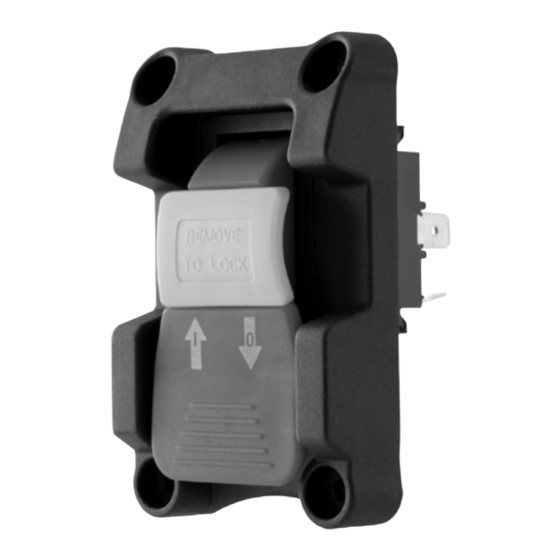
Figure 1. h8239 safety paddle switch.
Introduction
the Model h8239 features a large on/oFF pad-
dle with a removable safety key that can be used
to disable the switch. this switch is designed to fit
into
⁄
" x 1
⁄
" rectangular hole or mounted over a
7
5
8
8
1
⁄
" x 2
⁄
" rectangular hole with four #5 screws.
1
1
8
4
Specifications
rated horsepower ........................................ 2hp
rated Voltage ..................................... 125V/250V
rated Current Amperage .............................. 20A
Advertisement

Summary of Contents for Grizzly H8239
- Page 1 For questions or help with this product contact Tech Support at (570) 546-9663 or techsupport@grizzly.com To reduce risk of serious burns, electrocu- tion or death when installing this switch: • Only use this switch to replace an existing machine switch that has the same physi- cal configuration and equivalent electrical specifications/ratings.
- Page 2 Installation When installing the h8239 switch, use the wiring diagram in Figure 2 to ensure proper wire con- nections. This switch is intended to be connected to stranded wire with insulated quick-discon- nect crimp-type female wire terminals hav- ing a ⁄...


