Table of Contents
Advertisement
Quick Links
All manuals and user guides at all-guides.com
SERVICE MANUAL
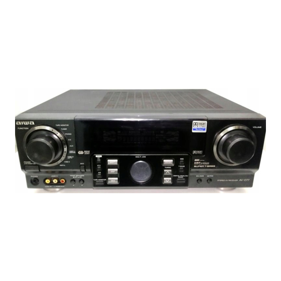
STEREO AV RECEIVER
• This Service Manual is the "Supplement" and replaces "Simple Manual"
(S/M Code No. 09-00A-429-6T3).
• This Service Manual contains information about the difference between
AV-D77 (HC) and AV-D77 (EZ). If requiring other information, see Service
Manual of AV-D77 (U,EZ), (S/M Code No. 09-007-429-6R2).
AV-D77
S/M Code No. 09-00B-429-6S1
HC
Advertisement
Table of Contents

Related Manuals for Aiwa AV-D77 HC


Summary of Contents for Aiwa AV-D77 HC
- Page 1 All manuals and user guides at all-guides.com AV-D77 SERVICE MANUAL STEREO AV RECEIVER • This Service Manual is the “Supplement” and replaces “Simple Manual” (S/M Code No. 09-00A-429-6T3). • This Service Manual contains information about the difference between AV-D77 (HC) and AV-D77 (EZ). If requiring other information, see Service Manual of AV-D77 (U,EZ), (S/M Code No.
-
Page 2: Specifications
All manuals and user guides at all-guides.com SPECIFICATIONS FM tuner section Outputs AUDIO OUT (REC OUT): 300 mV Tuning range 87.5 MHz to 108 MHz (1 kohm) Usable sensitivity (IHF) 13.2 dBf VIDEO OUT (MONITOR): 1 Vp-p Antenna terminals 75 ohms (unbalanced) (75 ohms) SUB WOOFER: 5.0 V AM tuner section... -
Page 3: Electrical Main Parts List
All manuals and user guides at all-guides.com ELECTRICAL MAIN PARTS LIST REF. NO. PART NO. KANRI DESCRIPTION REF. NO. PART NO. KANRI DESCRIPTION 87-A40-270-080 C-DIODE,MC2838 87-A40-004-080 ZENER,MTZJ16A 87-017-888-080 C-IC,NJM4558MD 87-A40-335-080 ZENER,MTZJ11C T-72 87-A21-501-010 C-IC,YSS902 87-070-274-080 DIODE,1N4003 SEM 87-A21-503-010 C-IC,AK4527VQ 87-A40-435-080 ZENER,MTZJ30D 87-020-903-010 IC,NJM7805FA... - Page 4 All manuals and user guides at all-guides.com REF. NO. PART NO. KANRI DESCRIPTION REF. NO. PART NO. KANRI DESCRIPTION C203 87-010-178-080 C-CAP,S 1000P-50 K B C411 87-016-526-080 C-CAP,S 0.47-16 BK C204 87-010-178-080 C-CAP,S 1000P-50 K B C412 87-010-402-080 CAP,E 2.2-50 M 11L SME C205 87-010-405-080 CAP,E 10-50 M 11L SME...
- Page 5 All manuals and user guides at all-guides.com KANRI REF. NO. PART NO. KANRI DESCRIPTION REF. NO. PART NO. DESCRIPTION C661 87-010-196-080 C-CAP,S 0.1-25 Z F R176 87-A00-401-050 RES,M/F 390-1W J VTP C700 87-018-203-080 CAP,TC U 8200P R179 87-A00-373-050 RES,M/F 270-1W J VTP C701 87-010-196-080 C-CAP,S 0.1-25 Z F C2012...
- Page 6 All manuals and user guides at all-guides.com KANRI REF. NO. PART NO. KANRI DESCRIPTION REF. NO. PART NO. DESCRIPTION C814 87-010-178-080 C-CAP,S 1000P-50 K B C2012 LED712 87-A40-317-080 LED,SLR-342VCT31 RED C815 87-010-196-080 C-CAP,S 0.1-25 Z F S801 87-A90-095-080 SW,TACT EVQ11G04M C816 87-010-312-080 C-CAP,S 15P-50 J CH GRM...
- Page 7 All manuals and user guides at all-guides.com KANRI REF. NO. PART NO. KANRI DESCRIPTION REF. NO. PART NO. DESCRIPTION C153 87-010-178-080 C-CAP,S 1000P-50 K B C2012 C225 87-012-155-080 C-CAP,S 180P-50 J CH GRM C154 87-010-178-080 C-CAP,S 1000P-50 K B C2012 C226 87-012-155-080 C-CAP,S 180P-50 J CH GRM...
- Page 8 All manuals and user guides at all-guides.com REF. NO. PART NO. DESCRIPTION REF. NO. PART NO. KANRI DESCRIPTION KANRI VOLUME C.B PR116 87-026-682-080 PROTECTOR,10A 491SERIES 60V 8Z-NF8-663-010 PT,SUB ZNF-8(H) C601 87-010-195-080 C-CAP,S 0.068-25 Z F C2012 PT101 8A-AR1-608-110 PT,AAR-1 HC (KAM1) C602 87-010-195-080 C-CAP,S 0.068-25 Z F C2012...
- Page 9 All manuals and user guides at all-guides.com REF. NO. PART NO. KANRI DESCRIPTION REF. NO. PART NO. KANRI DESCRIPTION C823 87-012-286-080 C-CAP, U 0.01-25 T102 87-A60-317-010 TERMINAL, 1P MSC C828 87-010-196-080 CHIP CAPACITOR,0.1-25 C829 87-010-196-080 CHIP CAPACITOR,0.1-25 C959 87-010-196-080 CHIP CAPACITOR,0.1-25 SPKR C.B C960 87-010-196-080...
-
Page 10: Transistor Illustration
All manuals and user guides at all-guides.com CHIP RESISTOR PART CODE Chip Resistor Part Coding Figure Resistor Code Value of resistor Chip resistor Dimensions (mm) Wattage Type Tolerance Symbol Resistor Code Form 1/16W 1005 0.35 1/16W 1608 0.45 1/10W 2125 1.25 0.45 1/8W... - Page 11 All manuals and user guides at all-guides.com WIRING – 1 (MAIN / VCC2 / VCC3) – 11 –...
- Page 12 All manuals and user guides at all-guides.com SCHEMATIC DIAGRAM – 1 (MAIN 1/2) – 12 –...
- Page 13 All manuals and user guides at all-guides.com SCHEMATIC DIAGRAM – 2 (MAIN 2/2 / VCC2 / VCC3) – 13 –...
- Page 14 All manuals and user guides at all-guides.com WIRING – 2 (FRONT) – 14 –...
- Page 15 All manuals and user guides at all-guides.com SCHEMATIC DIAGRAM – 3 (FRONT) – 15 –...
- Page 16 All manuals and user guides at all-guides.com WIRING – 3 (DIGITAL) – 16 –...
- Page 17 All manuals and user guides at all-guides.com SCHEMATIC DIAGRAM – 4 (DIGITAL) – 17 –...
- Page 18 All manuals and user guides at all-guides.com WIRING – 4 (VOLUME / VIDEO / GEQ) – 18 –...
- Page 19 All manuals and user guides at all-guides.com SCHEMATIC DIAGRAM – 5 (VOLUME / VIDEO / GEQ) – 19 –...
- Page 20 All manuals and user guides at all-guides.com WIRING – 5 (PT / AC – SW) – 20 –...
- Page 21 All manuals and user guides at all-guides.com SCHEMATIC DIAGRAM – 6 (PT / AC – SW) – 21 –...
-
Page 22: Wiring - 6 (Tuner)
All manuals and user guides at all-guides.com WIRING – 6 (TUNER) – 22 –... - Page 23 All manuals and user guides at all-guides.com SCHEMATIC DIAGRAM – 7 (TUNER) – 23 –...
- Page 24 All manuals and user guides at all-guides.com WIRING – 7 (SPKR) – 24 –...
- Page 25 All manuals and user guides at all-guides.com SCHEMATIC DIAGRAM – 8 (SPKR) – 25 –...
- Page 26 All manuals and user guides at all-guides.com WIRING – 8 (MIC / KEY CON) – 26 –...
- Page 27 All manuals and user guides at all-guides.com SCHEMATIC DIAGRAM – 9 (MIC / KEY CON) – 27 –...
-
Page 28: Ic Block Diagram
All manuals and user guides at all-guides.com IC BLOCK DIAGRAM – 28 –... - Page 29 All manuals and user guides at all-guides.com ADJUSTMENT <TUNER / FRONT> < TUNER SECTION > < FRONT SECTION > 1. µ-CON OSC Adjustment 1. Clock Frequency Check Settings : • Test point : TP1 and GND Settings : • Test point : TP2(CLK) Method : Set to AM 1602kHz and check that the test point is •...
- Page 30 All manuals and user guides at all-guides.com MECHANICAL EXPLODED VIEW 1 / 1 SP TERMINAL AZA-8 WIRE,BINDER HT-SINK, WIRE, TR VR BINDER PLATE, HT,SINK ASSY CHAS,FRONT PLATE, BOTTOM CHAS,MAIN WIRE,BINDER AV-D77 (HCNC1NC) (FileName:EXP.EPS) 12/10/18 (AAR-2) – 30 –...
-
Page 31: Mechanical Parts List
8 8A-AR3-069-010 RING,FUN GLD 43 88-AR2-205-110 HLDR,PWB OSD 9 8A-AR3-009-010 REFLECTOR,FUN 44 87-084-077-010 NYLON RIVET, 3.5-4.5 10 87-B00-002-010 BADGE,AIWA 30 ABS SIL A 87-067-703-010 TAPPING SCREW, BVT2+3-10 11 8Z-AR1-020-110 RING,FOOT SIL B 87-721-095-410 QT2+3-8GLD W/O SLOT 12 8A-AR2-002-010 CABI,FR H GLD... -
Page 32: Accessories / Package List
All manuals and user guides at all-guides.com ACCESSORIES / PACKAGE LIST REF. NO. PART NO. KANRI DESCRIPTION 1 8A-AR2-901-010 IB,H(EC-K)S 2 87-A90-030-010 ANT,LOOP AM-NC C 3 87-043-115-010 FEEDER-ANT,FM 4 8A-AR2-705-010 RC UNIT,RC-AAR02 – 32 –... - Page 33 All manuals and user guides at all-guides.com 2–11, IKENOHATA 1–CHOME, TAITO-KU, TOKYO 110, JAPAN TEL:03 (3827) 3111 9301978 0251431 Printed in Singapore...