Table of Contents
Advertisement
Quick Links
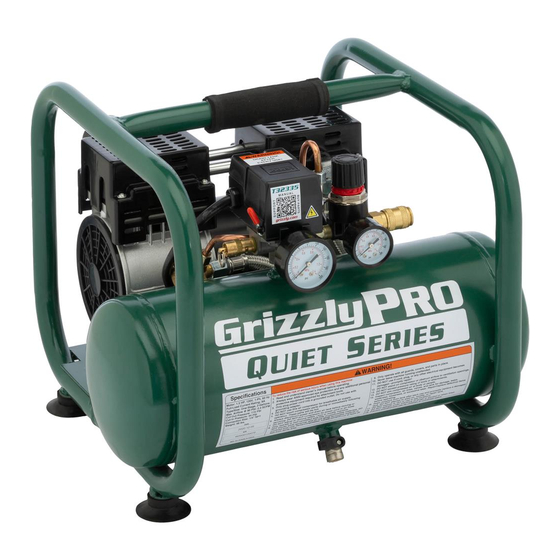
MODEL T32335
2-GALLON OIL-FREE QUIET
SERIES AIR COMPRESSOR
OWNER'S MANUAL
(For models manufactured since 11/20)
COPYRIGHT © MARCH, 2022 BY GRIZZLY INDUSTRIAL, INC.
WARNING: NO PORTION OF THIS MANUAL MAY BE REPRODUCED IN ANY SHAPE
OR FORM WITHOUT THE WRITTEN APPROVAL OF GRIZZLY INDUSTRIAL, INC.
#CS22176 PRINTED IN CHINA
V1.03.22
***Keep for Future Reference***
Advertisement
Table of Contents

Related Manuals for Grizzly QUIET Series


Summary of Contents for Grizzly QUIET Series
- Page 1 (For models manufactured since 11/20) COPYRIGHT © MARCH, 2022 BY GRIZZLY INDUSTRIAL, INC. WARNING: NO PORTION OF THIS MANUAL MAY BE REPRODUCED IN ANY SHAPE OR FORM WITHOUT THE WRITTEN APPROVAL OF GRIZZLY INDUSTRIAL, INC. #CS22176 PRINTED IN CHINA V1.03.22...
- Page 2 This manual provides critical safety instructions on the proper setup, operation, maintenance, and service of this machine/tool. Save this document, refer to it often, and use it to instruct other operators. Failure to read, understand and follow the instructions in this manual may result in fire or serious personal injury—including amputation, electrocution, or death.
-
Page 3: Table Of Contents
Table of Contents INTRODUCTION ..........................2 Contact Info ..........................2 Manual Accuracy ........................2 Identification ..........................3 Controls & Components ......................4 Machine Data Sheet ........................6 SECTION 1: SAFETY ........................8 Safety Instructions for Machinery ....................8 Additional Safety for Air Compressors ..................10 SECTION 2: POWER SUPPLY ...................... -
Page 4: Introduction
ID label. This will help us help you faster. tions, specifications, drawings, and photographs in this manual. Sometimes we make mistakes, but Grizzly Technical Support our policy of continuous improvement also means that sometimes the machine you receive is 1815 W. -
Page 5: Identification
Identification Become familiar with the names and locations of the controls and features shown below to better understand the instructions in this manual. Discharge Filter Line Pressure Switch Regulator Compressor Quick-Connect Pump Port Motor Line Pressure Gauge Roll Cage Safety Suction Tank Relief Valve... -
Page 6: Controls & Components
Controls & D. Pressure Switch Lever: Toggles pressure switch between OFF and AUTO modes. Components Machine is OFF in OFF mode, and will con- tinue to pressurize when in AUTO mode. Air Input To reduce your risk of serious injury, read this entire manual BEFORE... - Page 7 Air Output/Delivery Figure 5. Air output components. Figure 4. Location of pump and exhaust tube. K. Regulator Knob: Adjusts pressure of air delivered to quick-connect port. Turn clock- Dual Compressor Pump: Uses piston to wise to increase pressure and counterclock- draw in and compress air before transferring wise to decrease pressure.
-
Page 8: Machine Data Sheet
Machine Data Sheet Customer Service #: (570) 546-9663 · To Order Call: (800) 523-4777 · Fax #: (800) 438-5901 MODEL T32335 2-GALLON OIL-FREE QUIET SERIES AIR COMPRESSOR Product Dimensions: Weight....................................48.lbs. Width.(side-to-side).x.Depth.(front-to-back).x.Height..................17.x.16.x.14.in. Footprint.(Length.x.Width)............................10.x.13.in. Shipping Dimensions: Type..................................Cardboard.Box Content................................... Machine Weight.................................... - Page 9 Output Port Information Connection Type ............................Quick-Coupler Connection Size ..............................1/4" NPT Number of Connections ..............................1 Hose Included ................................No Construction Information Tank ...................................Steel Valves ................................Brass-Coated Cage/Frame ................................Steel Paint Type/Finish ..............................Enamel Other Specifications: Country of Origin ................................China Warranty ................................... 1 Year Serial Number Location ..............................
-
Page 10: Section 1: Safety
SECTION 1: SAFETY For Your Own Safety, Read Instruction Manual Before Operating This Machine The purpose of safety symbols is to attract your attention to possible hazardous conditions. This manual uses a series of symbols and signal words intended to convey the level of impor- tance of the safety messages. - Page 11 WEARING PROPER APPAREL. Do not wear FORCING MACHINERY. Do not force machine. clothing, apparel or jewelry that can become It will do the job safer and better at the rate for entangled in moving parts. Always tie back or which it was designed. cover long hair.
-
Page 12: Additional Safety For Air Compressors
Additional Safety for Air Compressors Serious impact injury or death can occur from bursting tank, attachment tool, distribution line, or hose. Contact with hot compressor parts can result in burns. Operating this tool in an environment without proper ventilation or near combustible materials can lead to explosions or fires. -
Page 13: Section 2: Power Supply
SECTION 2: POWER SUPPLY Availability Before installing the machine, consider the avail- ability and proximity of the required power supply Serious injury could occur if you connect circuit. If an existing circuit does not meet the machine to power before completing setup requirements for this machine, a new circuit must process. - Page 14 Grounding & Plug Requirements Improper connection of the equipment-grounding wire can result in a risk of electric shock. The This machine MUST be grounded. In the event wire with green insulation (with or without yellow of certain malfunctions or breakdowns, grounding stripes) is the equipment-grounding wire.
-
Page 15: Section 3: Setup
Grizzly or the shipping agent. You MUST have the original pack- Inventory (Figure 7) aging to file a freight claim. -
Page 16: Site Considerations
Site Considerations Assembly Workbench Load The machine must be fully assembled before it can be operated. Before beginning the assembly Refer to the Machine Data Sheet for the weight process, refer to Needed for Setup and gather and footprint specifications of your machine. all listed items. -
Page 17: Test Run
Test Run Move pressure switch lever to OFF position (see Figure 10). Once assembly is complete, test run the machine to ensure it is properly connected to power and safety components are functioning correctly. Pressure Switch If you find an unusual problem during the test run, Lever immediately stop the machine, disconnect it from power, and fix the problem BEFORE operating the... - Page 18 Do not touch compressor Releasing air through safety relief valve head or discharge line can be extremely loud. Protect hearing during use or immediately with ANSI-approved hearing protection in after compressor is active. following step. These hot parts may cause burns.
-
Page 19: Section 4: Operations
Puts on safety glasses. ects. Regardless of the content in this sec- tion, Grizzly Industrial will not be held liable Pulls safety valve ring to test valve and clear for accidents caused by lack of training. -
Page 20: Choosing Air Hose
Choosing Air Hose Fittings Many hoses come with fittings installed. The sim- plest option is to find a hose with two fittings: one that matches the compressor output port, and one There are many options when it comes to hoses. that matches your intended attachment tool. -
Page 21: Connecting Air Tool
Connecting Air Tool Operating Pressure (Pounds/Inch Your second consideration should be the recom- mended or required operating pressure of your tool. An air tool recommended for 70 PSI should There are various air tools that can be connected never be connected to a hose or system set to to your air compressor by means of an air hose, higher than that operating pressure, as the tool or and the setup will vary little across tools, but there... - Page 22 Disconnecting Air Tool Insert air hose male plug into quick-connect coupler (see Figure 19). Note: When plug is fully seated, coupler will Eye injury hazard! Always automatically lock it in place. wear safety glasses when handling pressurized air system. Plug To disconnect air tool: DISCONNECT MACHINE FROM POWER! Releasing air through safety relief valve...
-
Page 23: Section 5: Accessories
T20451—“Kirova” Clear Safety Glasses To reduce this risk, only install accessories T20456—DAKURA Safety Glasses, Black/Clear recommended for this machine by Grizzly. NOTICE T20503 Refer to our website or latest catalog for additional recommended accessories. - Page 24 3.5 lbs., and has a ⁄ " NPT air inlet. Includes a case. Figure 27. T23087 Air Brush Kit. Figure 25. H5527 18-Gauge Brad Nailer Kit. www.grizzly.com 1-800-523-4777 order online at or call -22- Model T32335 (Mfd. Since 11/20)
-
Page 25: Section 6: Maintenance
SECTION 6: MAINTENANCE Daily Maintenance • Open drain valve to drain any condensation. • Test function of safety relief valve and clear Compressor will turn ON any obstructions. automatically when pres- sure switch is set to AUTO. To reduce risk of shock/ accidental startup, always disconnect machine from Releasing air through safety relief valve or... -
Page 26: Draining Tank
Draining Tank Checking Air Filter Some water may accumulate in the tank depend- The air filter helps prevent impurities and dust ing on usage and humidity. Drain water from the from entering the compressor and reduces noise. tank daily to increase the lifespan of the compres- A dirty filter will result in a less efficient system sor and air tools and to prevent tank corrosion. -
Page 27: Machine Storage
Machine Storage To prepare machine for storage: DISCONNECT MACHINE FROM POWER! All machinery will develop serious rust problems and corrosion damage if it is not properly prepared for storage. Use the steps in this section to ensure Releasing air through drain valve can that your machine remains in good condition. -
Page 28: Checking For Leaks
Checking for Leaks Fixing Leaks Item Needed Teflon Tape or Pipe Dope ....As Needed Air leaks will cause low air output and increase To fix leaks: the time the compressor must run. DISCONNECT MACHINE FROM POWER! Checking for Leaks Disconnect tool and hose from compressor. -
Page 29: Section 7: Service
SECTION 7: SERVICE Review the troubleshooting procedures in this section if a problem develops with your machine. If you need replacement parts or additional help with a procedure, call our Technical Support. Note: Please gather the serial number and manufacture date of your machine before calling. Troubleshooting Motor &... - Page 30 Motor & Electrical (Cont.) Symptom Possible Cause Possible Solution Motor runs 1. Machine is undersized. 1. Use a smaller attachment tool or a larger air continuously. compressor. 2. Regulator needs to be adjusted for lower 2. Turn regulator knob counterclockwise to decrease line airflow delivery.
- Page 31 Operation (Cont.) Symptom Possible Cause Possible Solution Air leaks from 1. Check valve components are dirty/damaged. 1. Clean/replace check valve components (Page 30). air filter. 2. Reed valve(s) not sealing. 2. Remove cylinder head and replace reed valve(s). Air tools have 1.
-
Page 32: Examining Check Valve
Examining Remove cap shown in Figure 31 from check valve. Check Valve The check valve pushes compressed air into the Check Valve tank and prevents it from flowing back toward the pump. The diaphragm in the check valve can become damaged, twisted, or dirty and cause the valve to leak or prevent the compressor from pressurizing. -
Page 33: Adjusting Cut-In/Cut-Out Settings
Adjusting Cut-In/ Cut-Out Settings Releasing air through drain valve can be extremely loud. Protect hearing with ANSI-approved hearing protection while performing following step. The pressure switch ensures the compressor will turn ON when the tank pressure drops to approxi- mately 95 PSI (the cut-in pressure), and will turn Use safety relief valve to reduce tank pres- OFF when the tank pressure reaches 115 PSI (the sure to less than 10 PSI. - Page 34 — Turn screw half turn clockwise to increase both settings. — Turn screw half turn counterclockwise to decrease both settings. Install pressure switch cover. Pressure Connect machine to power, start compres- Switch sor, and cycle compressor through cut-in/ Cover cut-out pressures. If compressor does not automatically turn OFF at 115 PSI, turn machine OFF before pressure reaches 120 PSI.
-
Page 35: Section 8: Wiring
Technical Support at (570) 546-9663. The photos and diagrams included in this section are best viewed in color. You can view these pages in color at www.grizzly.com. -33- Model T32335 (Mfd. Since 11/20) -
Page 36: Wiring Diagram
Wiring Diagram MOTOR 120V RUN CAPACITOR CBB60 70uF 250V Neutral 120 VAC Ground PRESSURE SWITCH 5-15 Plug LEFOO LF10-4H Figure 37. Pressure switch wiring. Figure 38. Run capacitor wiring. READ ELECTRICAL SAFETY -34- Model T32335 (Mfd. Since 11/20) ON PAGE 33! -
Page 37: Section 9: Parts
SECTION 9: PARTS To order parts, contact MEGA by phone at (832) 415-6995 or email at CS@megacompressor.com. Main -35- Model T32335 (Mfd. Since 11/20) - Page 38 Main Parts List REF DESCRIPTION PART # REF DESCRIPTION PART # JC800-1 JC800-32 FAN COVER HEX NUT M5-.8 U1003 FAN (RIGHT) ROTOR JC800-34 JC800-3 CRANKCASE (RIGHT) BALL BEARING 6203ZZ JC800-35 JC800-4 CONNECTING ROD PHLP HD SCR M3-.5 X 12 JC800-36 JC800-5 PISTON RING PHLP HD SCR M4-.7 X 8...
-
Page 39: Labels & Cosmetics
Safety labels help reduce the risk of serious injury caused by machine hazards. If any label comes off or becomes unreadable, the owner of this machine MUST replace it in the original location before resuming operations. For replacements, contact (800) 523-4777 or www.grizzly.com. -37-...