Table of Contents
Advertisement
Quick Links
Advertisement
Chapters
Table of Contents

Related Manuals for Delta PhotoVoltaic RPI-C500


Summary of Contents for Delta PhotoVoltaic RPI-C500
- Page 1 PhotoVoltaic Inverter RPI-C500 PV Inverter...
-
Page 2: Table Of Contents
ABLE OF ONTENTS ABLE OF ONTENTS 1. Introduction ..............1 1.1. About This Manual ......................1 1.2. Valid Models ........................... 1 1.3. T arget Group .......................... 1 2. Safety ................. 2 2.1. System Usage ........................2 2.2. Disconnecting ........................2 3. - Page 3 ABLE OF ONTENTS 4.5. Package Contents ......................16 5. Installation ..............17 5.1. Recommended T ools ......................17 5.2. DC Connection ........................17 5.2.1. Dimension of DC Busbar ..................19 5.2.2. Choose Input DC Fuse and Cable Size ............21 5.2.3.
- Page 4 ABLE OF ONTENTS 5.10.3. Fault Ride Through (FRT) ................38 5.11. LCD Flowchart ........................40 5.11.1. Home Page ......................40 5.11.2. Power Meter ......................41 5.11.3. Energy Log ......................41 5.11.4. Event Log ....................... 42 5.11.5. Operation Data ....................43 5.11.6.
- Page 5 7.5. Replacing Surge Protection Device (SPD) ............... 70 Appendix A. Technical Data ......... 72 Appendix B. Cable Combination Table & Hole Size of plate 76 Appendix C. Delta MV Transformer and Auxiliary Power transformer Application Note ..........77 Appendix D. Contact Information ........81 NSTALLATION EFERENCE...
- Page 6 ONVENTIONS Conventions General Conventions The following conventions are used in this manual: Example: Indicates information used to demonstrate or explain an associated concept. Note: Indicates additional information that is relevant to the current process or procedure. WARNING! Warning information appears before the text it references to emphasize that the content may prevent damage to the device or equipment.
-
Page 7: About This Manual
Delta may modify or update the Manual from time to time without any notice. Delta will do its best efforts to keep the Manual updated and maintain the accuracy of the Manual. Delta disclaims any kinds or forms... -
Page 8: Introduction
1.2. Valid Models This user manual describes the installation procedures, maintenance, technical data and safety instruction of the following solar inverter models under Delta brand. ● RPI-C500 PV Inverter 1.3. Target Group The guidelines in this manual provide instructions for a person who is well training and skillful for the installation of the central inverter. -
Page 9: Safety
6%. This external transformer is required to be located between the output of the central inverter and the utility power connection. For the application of MV transformer .Please refer to the Appendix C “ Delta MV transformer application note”. - Page 10 AFETY ISCONNECTING Simply switching off the main AC and DC switches is not sufficient to ensure proper isolation of the device. The main switches only separate the power circuit from the grid and the photovoltaic generator. CAUTION! ISK OF LETHAL ELECTRIC SHOCK Dangerous accidental-contact voltages can be present in the PV Inverter even when the main AC and DC switches are switched off! ...
-
Page 11: Product Overview
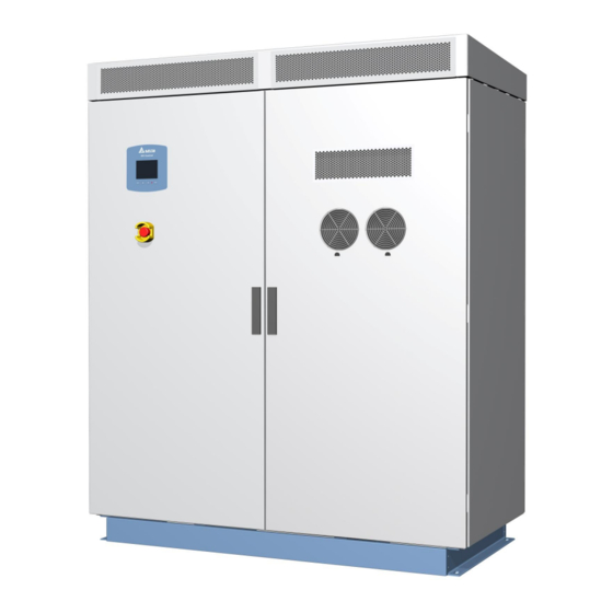
ESCRIPTION 3. Product Overview 3.1. Product Description The Delta RPI inverter models include the RPI-C500. It is manufactured to meet high standards of quality and to maximize the yield of every solar plant (up to 98.7% efficiency). The RPI series include a IP-65 protection level enclosure and corrosion resistant features to ensure the protection of the inverter within an indoor or outdoor environment. - Page 12 RODUCT VERVIEW NTERIOR RONT 3.2.2. Exterior Triangle View Air Filter Figure 3-2. Exterior Rear View NSTALLATION ANUAL...
-
Page 13: Features
RODUCT VERVIEW EATURES 3.3. Features The following are important features of the product(s) described in this manual: ● High efficiency, peak 98.7%, EUR 98.4% ● 3 Phase (3 Lines + PE) 500kVA solar inverter ● Wide input range (420-1000Vdc) ● Wide MPPT range (450-820Vdc) ●... -
Page 14: Transportation & Installation Preparation
& I RANSPORTATION NSTALLATION REPARATION NSTALLATION EQUIREMENTS 4. Transportation & Installation Preparation 4.1. Installation Site Requirements 4.1.1. Site Space Make sure the room for system loading and the destination installation site meet the space requirements described in this section. Figure 4-1. Inverter Space Requirements The loading site should provide enough space to unpack the entire system and release the container. -
Page 15: Preparing The Installation Site
& I RANSPORTATION NSTALLATION REPARATION REPARING THE NSTALLATION 4.2. Preparing the Installation Site Prior to unpacking the system, make sure that you read and understand all environ- mental and space requirements. 4.2.1. Dimensions of trench Prepare a trench for laying cables from DC and AC distribution box safely. The suggested width of trench is 250mm (shaded area in Figure 4-2) and the suggested depth is depended on user. -
Page 16: Fixed Methods
& I RANSPORTATION NSTALLATION REPARATION IXED ETHODS 4.2.3. Fixed Methods You can install the inverter: 1. Install on the ground directly. 2. Install on the base mounted on the ground. Rear Front Rear Front Trench Base Figure 4-4. Fixed Methods 4.2.4. -
Page 17: Delivery Options And Recommended Vehicle
& I RANSPORTATION NSTALLATION REPARATION SING ORKLIFT ALLET RUNK Internal Air Outlet Unit: mm Figure 4-6. Internal air outlet dimensions (top view) 4.3. Delivery Options and Recommended Vehicle Any equipment used for the transport of the central inverter must be suitable for the weight of the central inverter. -
Page 18: Using A Forklift Or Pallet Trunk
& I RANSPORTATION NSTALLATION REPARATION SING RANE 4.3.1. Using a Forklift or pallet trunk The method of moving the central inverter by using a forklift or pallet trunk is the same whether the unit is packed in a shipping crate or not. Follow these steps: 1. - Page 19 & I RANSPORTATION NSTALLATION REPARATION SING RANE If the unit is unpacked in a shipping crate: 1. Open the front and back door of the central inverter. 2. Loosen the screws on the top cover. Figure 4-9. Loosen the Screws on the Top Cover 3.
- Page 20 & I RANSPORTATION NSTALLATION REPARATION SING RANE 4. Attach the hoisting hooks and cables to the steel rings on the inverter. Crane Hook Steel Ring Hoisting Hook Figure 4-11. Attaching the Hoisting Cables 5. Attach the crane hook to the steel ring on the hoisting cables. 6.
-
Page 21: Unpacking
& I RANSPORTATION NSTALLATION REPARATION NPACKING 4.4. Unpacking To unpack the central inverter from shipping crate, follow these steps: 1. Remove top cover of paper case and then remove the paper box in clockwise direction. Figure 4-12. Removing the paper case 2. -
Page 22: Package Contents
& I RANSPORTATION NSTALLATION REPARATION ACKAGE ONTENTS 3. Remove the central inverter from the pallet. Figure 4-14. Removing the Central Inverter from the Pallet 4.5. Package Contents Table 4-1: Package Contents Object Description Central Inverter RPI-C500 Inverter Open/Close the door of the inverter The instruction to provide the information of safety, installation, Installation Manual specification, etc. -
Page 23: Installation
NSTALLATION ECOMMENDED OOLS 5. Installation 5.1. Recommended Tools Only use tools that have been recommended to install the unit. ● Power meter (power analyzer) ● Voltmeter ● Current meter ● Adjustable / Torque / Socket Wrench ● Screwdriver 5.2. DC Connection 1. - Page 24 DC C NSTALLATION ONNECTION 2. Connect the power cables from the DC distribution box to the PV Inverter shown in Figure 5-2. Figure 5-2. DC Connection Maximum No. of conductor (+/-) Screw/Nut size Torque requirement (Nm) DC Terminal Minimum total cable size requirement for DC+/DC- DC Cable 600mm Note:...
-
Page 25: Dimension Of Dc Busbar
Note: For cable size and number other than the default setting. You must consult with manufacturer (Delta Electronics) in advanced for other cable combinations. Please follow these steps when using other cable combinations. 1. Check the terminal lug of the cable whether to match the connection with the terminal of busbar, including the hole size of screw and the width of screw hole on busbar. - Page 26 DC C NSTALLATION ONNECTION Figure 5-4. Dimensions of the DC connection lugs NSTALLATION UIDE...
-
Page 27: Choose Input Dc Fuse And Cable Size
Note: 1. The default setting of fuse is 250A*8 runs. 2. Must consult with Delta in advanced if using other rating type of fuse. 5.2.3. Positive/Negative Grounding The PV array can be grounded using positive grounding or negative grounding. To ground the PV array follow these steps: (Figure 5-5) 1. -
Page 28: Ac Connection
NSTALLATION ONNECTION 5.3. AC Connection 1. Thread the AC power cables through the bottom plate located shown in Figure 5-6. Figure 5-6. AC Power Cable Wiring NSTALLATION UIDE... - Page 29 NSTALLATION ONNECTION 2. Connect the power cables from the AC distribution box to the PV Inverter shown in Figure 5-7. Figure 5-7. AC Connection Maximum No. of conductor for Screw/Nut size Torque requirement (Nm) each phase AC Terminal Minimum total cable size requirement for each phase AC Cable 550mm Note:...
-
Page 30: Dimension Of Ac Busbar
NSTALLATION ONNECTION Note: Need to use moving bushing and silicon rubber for waterproof and dust. The recommended material of movable bushing and silicon rubber is shown as below: Component Part number Vendor Movable bushing KG-020 KANG YANG HARDWARE Silicon rubber RTV162 GE Bayer Silicones 5.3.1. - Page 31 NSTALLATION ONNECTION Figure 5-9. Dimensions of the AC connection lugs NSTALLATION UIDE...
-
Page 32: Pe Connection
PE C NSTALLATION ONNECTION 5.4. PE Connection There are two positions that can be connected to PE. 1. Inverter inside. Connect PE to the busbar in AC or DC side. 2. Inverter outside. Connect PE to the inverter holder. AC side DC side Figure 5-10. -
Page 33: Dimension Of Pe Busbar
PE C NSTALLATION ONNECTION 5.4.1. Dimension of PE Busbar Figure 5-11. Dimensions of the PE connection lugs Maximum No. of conductor (DC/AC) Screw/Nut size Torque requirement (Nm) PE Terminal Minimum total cable size requirement PE Cable 250mm CAUTION! The working temperature of cable should be 105°C. Note: Please follow these steps when using other cable combinations. -
Page 34: Dc Fuse Installation
NSTALLATION NSTALLATION 5.5. DC Fuse Installation 1. Loosen the screws on the busbars, and then take the busbars off. Figure 5-12. Remove screws and busbars 2. The steps of DC+ and DC- are the same, so install busbars and fuses, follow these steps: ●... -
Page 35: Attach/Remove The Plates
TTACH EMOVE LATES NSTALLATION 5.6. Attach/Remove the Plates To attach the plates, follow these steps: 1. Attach the plates to the front and back of the bottom of the central inverter. 2. Tighten the screws on the both side of the plates. Figure 5-14. -
Page 36: Connection Of Communication Modules
NSTALLATION ONNECTION OF OMMUNICATION ODULES 5.7. Connection of Communication Modules The Communication Module provide the function of communication with 2-port RS-485 and 2-port dry contacts. 5.7.1. RS-485 Connection The pin definition of RS-485 is shown as in Table 5-1. Installer should switch ON the terminal resistor when single inverter is installed. -
Page 37: Dry Contact Connection
NSTALLATION ONNECTION OF OMMUNICATION ODULES Figure 5-17. Multi-inverter Connection Illustration Table 5-2: RS-485 Data Format Baud rate 9600 Data bit Stop bit Parity Table 5-3: Terminal Resister Setting Terminal Resistor SW ON SW OFF 5.7.2. Dry Contact Connection Provide 2 set of Dry Contact function for gird and fault respectively. When inverter is on grid, COM &... -
Page 38: Auxiliary Power From External Source
NSTALLATION UXILIARY OWER FROM XTERNAL OURCE 5.8. Auxiliary Power from External Source If the power source of AC auxiliary power is changed from internal to external source, follow these steps: 1. Disconnect the terminal cables from the AC breaker. Note: The external power source should be able to provide with voltage 3P3W - 270Vac/315Vac/380Vac/400Vac ±15%, 50/60Hz, and power rating –... - Page 39 NSTALLATION UXILIARY OWER FROM XTERNAL OURCE 3. Remove the cables from the AC auxiliary power terminal block and AC breaker. Figure 5-20. Removing the Cables 4. Thread the external power cables through the cable gland from external source. Figure 5-21. Auxiliary Power from External Source 5.
-
Page 40: First Time Powering Up
NSTALLATION OWERING P THE NVERTER AND TEST 5.9. First Time Powering Up 5.9.1. Before Powering Up 1. Check the PV array. Note: The PV array open circuit DC voltage must be greater than 500Vdc and less than 1000Vdc. a. Measure the PV array open circuit DC voltage across the DC positive (+) and negative (-) terminals in DC distribution. - Page 41 NSTALLATION OWERING P THE NVERTER AND TEST i. The Main Menu screen is displayed and the setup is complete. EXIT Confirm Country Select Country– 1/1 Select Language 21. Jun 2010 13:50 21. Jun 2010 13:50 21. Jun 2010 13:50 English China Are you sure you to set country Deutsch...
-
Page 42: Active/Reactive Power Control And Fault Ride Through
NSTALLATION CTIVE EACTIVE OWER ONTROL AULT HROUGH 5.10. Active/Reactive Power Control and Fault Ride Through User can only set Active/Reactive power control in Grid System = Germany MV, India, or China (User has to key in password to change these settings). Fault ride through (FRT) can only be set in Grid System = Germany MV, India, or China. -
Page 43: Reactive Power Control
NSTALLATION CTIVE EACTIVE OWER ONTROL AULT HROUGH Figure 5-23. Power vs. frequency characteristic 5.10.2. Reactive Power Control According to BDEW: With active power output, it must be possible to operate the generating plant in any operating point with at least a reactive power output corresponding to a active factor at the network connection point of cos φ... -
Page 44: Fixed Reactive Power
NSTALLATION CTIVE EACTIVE OWER ONTROL AULT HROUGH 5.10.2.3. Fixed Reactive Power Once user enables this method, inverter will deliver reactive power (ie. Q) according to the fixed reactive power setting. The setting range is from Cap 60% to Ind 60%. 5.10.2.4. - Page 45 NSTALLATION CTIVE EACTIVE OWER ONTROL AULT HROUGH Below the blue line shown in Figure 2.5.1.2-2, there are no requirements saying that generating plants have to remain connected to the network. Voltage drops with values above the borderline 1 must not lead to instability or to the disconnection of the generating plant from the network (TC2007;...
-
Page 46: Lcd Flowchart
LCD F NSTALLATION LOWCHART 5.11. LCD Flowchart Press EXIT button will enter menu page (Figure 5-28), E-today is the home page for the following items in this section. Menu 21. Jun 2010 13:50 E-Today Power Meter Energy Log Event Log Operation Data Inverter Information Settings... -
Page 47: Power Meter
NSTALLATION OWER ETER 5.11.2. Power Meter This page shows the information about input and output power. Power Meter – 1/2 Power Meter – 2/2 21. Jun 2010 13:50 21. Jun 2010 13:50 DC Input: AC Output: Input1 Input2 Volt. UV 270 / VW 269 / WU 271 100200 101800 Curr. -
Page 48: Event Log
NSTALLATION VENT 5.11.4. Event Log When entering this page, the display will show all the events (error or fault) and it can show 30 records at most with the latest one on the top. When pressing ENT, user can view all the statistic data. Event Log Event Summary –... -
Page 49: Operation Data
NSTALLATION PERATION 5.11.5. Operation Data Have 4 pages; record the maximum and/or minimum values of history, including volt- age, current, power and temperature. Operation Data – 1/4 Operation Data – 2/4 21. Jun 2010 13:50 21. Jun 2010 13:50 Maximum Input1 Maximum (Vdc) -
Page 50: Inverter Information
NSTALLATION NVERTER NFORMATION 5.11.6. Inverter Information This page has the following information: serial number, firmware version, installation date and inverter ID. If user wants to change inverter ID, please refer to Settings. Inverter Information Inverter Information 21. Jun 2010 13:50 21. -
Page 51: Personal Settings
NSTALLATION ETTINGS 5.11.7.1. Personal Settings User can set Language, Date, Time, Screen Saver, LCD brightness and contrast in Personal Settings. Screen Saver can adjust from 5min-60min. When over the setting time limitation without using button functions, the LDC backlight will turn off automatically. -
Page 52: Install Settings
NSTALLATION ETTINGS 5.11.7.3. Install Settings Correct passwords are requested when entering Install Settings. Install Settings for user and installation technician are different. The password cannot be revised. After confirmation as the general user password, user can set Inverter ID, and Insulation. CAUTION! AUTIONS APPEAR BEFORE THE TEXT IT REFERENCES CAUTIONS APPEAR IN CAPITAL LETTERS... - Page 53 NSTALLATION ETTINGS set country as “Custom”. Return to Factory will turn inverter to default setting and delete all the records of event and energy. Install Settings – 1/2 Install Settings – 2/2 21. Jun 2010 13:50 21. Jun 2010 13:50 Inverter ID 60 s Reconnection Time...
- Page 54 NSTALLATION ETTINGS Table 5-4: Grid Setting Parameters Parameter Description Inverter will be disconnected from grid if the phase voltage of AC rises to Vac High Off this value. Inverter will be reconnected to grid if the phase voltage of AC drops to this Vac High On value.
-
Page 55: Active/Reactive Power Control
NSTALLATION ETTINGS Table 5-4: Grid Setting Parameters (Continued) The function is same as Fac Low Off, but the value must be higher than Fac Low Off Slow former. The function is same as Fac Low On, but the value must be higher than Fac Low On Slow former. -
Page 56: Power Vs. Frequency
NSTALLATION ETTINGS 5.11.7.4.2. Power vs. Frequency Gradient means the slope of power reduction, ie. –xx%/Hz Active Power Control 21. Jun 2010 13:50 Actual/Rated Power Actual Statism 50.30 Start Frequency Stop Frequency Recovery Frequency ] Hz Statism Recovery Time ( Hz ) Mode stop recovery... -
Page 57: Constant Reactive Power
NSTALLATION ETTINGS 5.11.7.4.5. Constant Reactive Power When this Mode is turned on, inverter will maintain reactive power as a constant value. Active/Reactive Power Reactive Power Control 21. Jun 2010 13:50 21. Jun 2010 13:50 Constant cosφ Reactive Power (Q/Sn) cosφ(P) Mode Constant Reactive Power Q(V) -
Page 58: Frt (Fault Ride Through)
NSTALLATION ETTINGS 5.11.7.5. FRT (Fault ride through) Users can refer to the figure below and fine tune the parameters in FRT setting page. FRT – 1/2 21. Jun 2010 13:50 Dead band - Vh Dead band - Vl K factor K factor U/Un Vdrop... -
Page 59: Troubleshooting
ROUBLESHOOTING EASUREMENT NDEX 6. Troubleshooting 6.1. Measurement Index Please refer to the following tables for definition of Measurement Index. E-Today: 1175kWh Power Meter – 1/2 Power Meter – 2/2 21. Jun 2010 13:50 21. Jun 2010 13:50 21. Jun 2010 13:50 DC Input: Runtime: 8.2Hrs Power:... - Page 60 ROUBLESHOOTING EASUREMENT NDEX Operation Data – 1/4 Operation Data – 2/4 21. Jun 2010 13:50 21. Jun 2010 13:50 Maximum Input1 Maximum (Vdc) Voltage Voltage (Vdc) Current 763.0 Current (kW) Power 170.0 Power (kW) 280.0 Voltage (Vdc) Current 758.0 Input2 Power 169.0 (kW)
- Page 61 ROUBLESHOOTING EASUREMENT NDEX Table 6-1: Measurement Index (Continued) Measurement Meaning AC Output - Power Factor Power factor of AC Output Life Energy Total energy generated to present time Life Runtime Accumulated operation time to present time Total CO saved Accumulated CO emission retrenched to present time Total Earning Accumulated the total amount of money earned...
- Page 62 ROUBLESHOOTING EASUREMENT NDEX Table 6-1: Measurement Index (Continued) Measurement Meaning Output Frequency Maximum The maximum Grid frequency from history Inside Max. The maximum inverter inner temperature value Heatsink-R Max. The maximum Heatsink-R temperature value Heatsink-S Max. The maximum Heatsink-S temperature value Heatsink-T Max.
-
Page 63: Error Message And T Rouble-Shooting
ROUBLESHOOTING RROR ESSAGE AND ROUBLESHOOTING 6.2. Error Message and Trouble- shooting Ones can check the Error Message on LCD then make simple and quick trouble shooting according to the following table. Table 6-2: Error Messages Message Possible cause Action 1. Check the utility frequency on the 1. - Page 64 ROUBLESHOOTING RROR ESSAGE AND ROUBLESHOOTING Table 6-2: Error Messages (Continued) Message Possible cause Action 1. Modify the PV array setting, and 1. Actual PV array voltage is over make the Voc less than 1000Vdc 1000Vdc Solar1 High 2. Check the detection circuit inside 2.
- Page 65 ROUBLESHOOTING RROR ESSAGE AND ROUBLESHOOTING Table 6-4: Fault Message Message Possible cause Action 1. Check the installation ambient ° 1. The ambient is over 60 C (The and environment Temperature installation is abnormal) 2. Check the detection circuit inside 2. Detection circuit malfunction the inverter 1.
- Page 66 ROUBLESHOOTING RROR ESSAGE AND ROUBLESHOOTING Table 6-4: Fault Message (Continued) Message Possible cause Action 1. Check the auxiliary circuitry inside 1. Auxiliary power circuitry the inverter HW Red ADC2 malfunction 2. Check the detection circuit inside 2. Detection circuit malfunction the inverter 1.
- Page 67 ROUBLESHOOTING RROR ESSAGE AND ROUBLESHOOTING Table 6-4: Fault Message (Continued) Message Possible cause Action 1. N/A 1. Surge occurs during operation 2. Check the driver circuit in inverter stage 2. Driver for inverter stage is AC Current High defective 3. Check all switching devices in inverter stage 3.
-
Page 68: Maintenance
AINTENANCE EPLACING COMPONENTS 7. Maintenance 7.1. Replacing a Fan Module 1. Pull and rotate the handle and then open the rear panel door Figure 7-1. Pull and rotate the handle NSTALLATION UIDE... - Page 69 AINTENANCE EPLACING A ODULE 2. Disconnect the connectors of the fan modules. Figure 7-2. Disconnecting the Connectors 3. Loosen the screws and nuts securing the bottom fan module to the chassis and remove the module. Figure 7-3. Loosening Bottom Fan Module Screws NSTALLATION UIDE...
- Page 70 AINTENANCE EPLACING A ODULE 4. Loosen the screws securing the top fan module to the chassis and remove the module. Figure 7-4. Loosening Top Fan Module Screws NSTALLATION UIDE...
-
Page 71: Replacing An Air Filter
AINTENANCE EPLACING AN ILTER 7.2. Replacing an Air Filter 1. Pull and rotate the handle and then open the rear panel door Figure 7-5. Pull and rotate the handle 2. Loosen the screws securing the air filter cover to the rear panel door and then open the cover. - Page 72 AINTENANCE EPLACING AN ILTER 3. Loosen the screws securing the air filter to the rear panel door. Figure 7-7. Loosening Air Filter Screws 4. Loosen the filter. Figure 7-8. Loosening the Air Filter NSTALLATION UIDE...
-
Page 73: Clean Air Outlets
AINTENANCE LEAN UTLETS 7.3. Clean Air Outlets 1. Open the front door of the central inverter. 2. Loosen the nuts on the plates of air outlets. Figure 7-9. Loosening the nuts of air outlets 3. Move the plates of air outlets to the right. Figure 7-10. - Page 74 AINTENANCE LEAN UTLETS 4. Remove the plates and air outlets directly. Figure 7-11. Remove the air outlets NSTALLATION UIDE...
-
Page 75: Replacing Dc Fuses
DC F AINTENANCE EPLACING USES 7.4. Replacing DC Fuses 1. Switch AC and DC power off and check no residue voltage exists on DC/AC side. 2. Loosen the screws on the fuses, and then take the old fuses off. 3. Put the new fuses and screws on the busbar, and then tighten the screws. Figure 7-12. -
Page 76: Replacing Surge Protection Device (Spd)
AINTENANCE EPLACING URGE ROTECTION EVICE 7.5. Replacing Surge Protection Device (SPD) Once the inverter encounters voltage spikes (e.g. struck by lightning) SPD will protect the inverter and got damaged. If you find a warning message “DC Surge” or “AC Surge” shown on display panel, please follow the steps below to replace the SPD. 1. - Page 77 AINTENANCE EPLACING URGE ROTECTION EVICE 4. Pull out the damaged unit and replace a new one. Figure 7-15. Pull out the SPD unit NSTALLATION UIDE...
-
Page 78: Appendix A. Technical Data
PPENDIX Appendix A. Technical Data Type of Equipment Outdoor enclosure Grid tied PV inverter Input Absolute maximum PV input 1000Vdc voltage 420/485*Vdc – 1000Vdc Operation voltage range 450/500*Vdc – 820Vdc Maximum power MPPT range MPPT accuracy > 99.9% at rated power Inverter wake up voltage <... - Page 79 PPENDIX Output Output capacity 500kVA Grid Three phase (3P3W-IT) Utility voltage range 243~378VΔ Utility frequency 50/60Hz Domestic regulation (Max 50/60Hz Utility frequency range ± 5Hz) Maximum output current 1080A Anti-islanding Domestic regulation Connect to utility after utility recover Output reconnect and countdown finished Reconnect time Domestic regulation...
- Page 80 PPENDIX Information Communication Port RS-485 Delta Protocol ● Operation: Green (Flashing during countdown) ● Alarm: Red 5” Graphic, 320*240 pixels LCD display Display buttons 4 operational buttons Energy log Day/Month/Year ● 30 events recently Event Log ● Event times for each event...
- Page 81 PPENDIX Environment Vibration ISTA 1E Drop ISTA 1B Mechanical Dimension Width 1600mm Depth 800mm High 1950mm Weight 1300kg Cooling Air cooling with Fans with inlet filter Enclosure rating IP-65 (Electric parts) Note: ” * ” When AC output voltage is 315Vac. NSTALLATION UIDE...
-
Page 82: Appendix B. Cable Combination Table & Hole Size Of Plate
PPENDIX Appendix B. Cable Combination Table & Hole Size of plate DC Side bottom plate Allowable Cable Gland Overall diameter Maximum hole No. of DC bottom plate Model No. of Cable ( mm ) AVC-MGB40-25-SD Ø 26.7 ~ 21.3 Note: “a”... -
Page 83: Appendix C. Delta Mv Transformer And Auxiliary Power Transformer Application Note
PPENDIX Appendix C. Delta MV Transformer and Auxiliary Power transformer Application Note A. Technical requirement of MV transformer A.1 The required insulation voltage of low voltage winding in MV transformer should To endure the pulse mode voltage of inverter with a maximum 1310V to earth. - Page 84 PPENDIX Each inverter require a separate isolated voltage winding. It is forbid to use several inverters in parallel with one low voltage winding. A.3 The MV transformer can be oil-type or dry-type. A.4 It is suggested to have tap changer on the high voltage side to align the voltage level to medium voltage.
- Page 85 PPENDIX B.1 Technical requirement of two-winding transformer - The voltage impedance should line between 4.0-6.0% - The vector grouping of two-winding transformer can be Dy11 or YNd11 * Please use DC+ to earth ground or DC- to earth ground if YNd11 is applied. YNd11 Dy11 B.2 Technical requirement of three-winding transformer...
- Page 86 216V ~ 438V and power rating should be larger than 2.8kVA. The output of transformer can be either Star or Delta connection for the auxiliary power. If the Neutral point of Star connection is brought out, to leave it unconnected. Inverter...
-
Page 87: Appendix D. Contact Information
PPENDIX Appendix D. Contact Information Delta Power Solutions India Pvt Ltd Ozone Manay Tech Park, "A" Block, 3rd Floor, Hosur Road, Hongasandra Village, Bangalore-560068. Tel: +91 80 6716 4777, Fax: +91 80 6716 4784. Website: www.deltaelectronicsindia.com / www.solar-inverter.com Sales Contact (All India) : Email: invertersales@delta.co.in... - Page 88 NSTALLATION UIDE...
- Page 89 光伏逆变器 RPI-C500 光伏逆变器...
- Page 90 目录 目录 1. 前言 ................1 1.1. 关于此手册 ..........................1 1.2. 适用机型 ........................... 1 1.3. 适用对象 ........................... 1 2. 安全规范 ............... 2 2.1. 光伏逆变器系统配置 ....................... 2 2.2. 断电 ............................2 3. 产品外观 ............... 4 3.1. 产品说明 ........................... 4 3.2. 产品检视 ........................... 4 3.2.1.
- Page 91 目录 4.4. 包装拆解 ..........................15 4.5. 物品清单 ..........................16 5. 安装说明 ..............17 5.1. 建议工具 ..........................17 5.2. DC 端连接 ..........................17 5.2.1. DC 端铜排尺寸 ......................19 5.2.2. 如何选择 DC 端保险丝与缆线尺寸 ................21 5.2.3. 正接地与负接地 ......................21 5.3. AC 端连接 ..........................22 5.3.1.
- Page 92 目录 5.10.2.3. 固定无功因素 ....................38 5.10.2.4. 无功功率/电压特性 Q(U) ................38 5.10.3. 故障穿越(FRT) ....................38 5.11. LCD 显示画面及操作 ......................40 5.11.1. Home Page ......................40 5. 11 .2. Power Meter ......................41 5.11.3. Energy Log ......................41 5. 11 .4. Event Log ....................... 42 5.
- Page 93 7.3. 清理排气孔滤网 ........................67 7.4. 更换 DC 保险丝 ........................69 7.5. 更换 Surge Protection Device (SPD) ................. 70 附录 A. 技术数据 ..............72 附录 B. 缆线组合列表与底板开孔尺寸 ........76 附录 C. Delta 中压变压器与辅助电源变压器应用说明 ..... 77 附录 D. 连络我们 ............... 81 安装参照...
- Page 94 图标和字体 图标与字体 一般标示 以下所提到的标志常见于本手册中: 范例: 此图样出现的目的是要解说相关的概念。 说明: 此图样出现的目的是要说明相关的程序或参考步骤。 警告! 此图标出现在某一段文字之前是要强调该段文字陈述的操作内容可能导致机器设备的损毁。 注意! 此图标出现在某一段文字之前是要强调该段文字陈述的操作内容可能导致人身的安全发生危 害。 印刷字体规范 以下所提到的字体规范常见于本手册中。 斜体字 常见于标题,目录,档案,路径和程序中。 屏幕显示 屏幕显示为计算器输出内容,包含操作菜单,开头提示字,响应输入内容 以及错误信息。 粗体字 出现粗体字时表示使用者要在键盘上按下这个字。 安装参照...
- Page 95 著作权 著作权 本安装手册的拥有权和智慧财产权,涵盖的范围包含文字叙述,数据和图样皆属于台 达电子股份有限公司(以下称”台达电子”)拥有。本手册的目的仅在说明本机器的操作 使用方式,没有台达电子的书面同意,对于本手册任何行式的给予或转让、复制、散 拨、再制、修改、翻译、摘录或其它使用行为一律禁止。为了本产品的持续研发或改 良,台达电子将在未通知顾客的情况下,不定期修改或更新手册内容。台达电子将尽 其所能更新手册并维持其正确性。台达电子谨此声明,不负责任何与本手册有关之明 示或默示担保责任。同时,台达电子不会就本手册及其有关文件之准确性、可靠性或 作出任何保证及担保。 Copyright © 2013 Delta Electronics, Inc. All Rights Reserved. 安装参照...
-
Page 96: 关于此手册
关于此手册 前言 1. 前言 1.1. 关于此手册 本手册记载了本机 RPI-C500 光伏逆变器的详细规格、操作步骤和相关的功能设定。 安装技师必须经过合格的光伏逆变器安装训练,在安装时也必须严格遵守安全指示和 操作步骤。 1.2. 适用机型 本手册在本公司的授权下记载了以下光伏逆变器的操作程序、维修方式、技术数据和 安全规范。 ● RPI-C500 光伏逆变器 1.3. 适用对象 本手册所陈列之操作步骤皆需经由良好训练的合格光伏逆变器安装技师来操作。 安装手册... -
Page 97: 光伏逆变器系统配置
安全规范 光伏逆变器系统配置 2. 安全规范 2.1. 光伏逆变器系统配置 光伏逆变器 系统配置如图 2-1。 图 2-1. 光伏逆变器系统配置 外部输出变压器需求 此外接变压器规格必须使用一次侧和二次侧之间的绕线可以承受至少 500kVA,其阻 抗变化最多不能超过 6%。此变压器必须要置于本机和市电之间。 有关于中压系统变压器的应用可以参考附录 C “Delta 中压变压器与辅助电源变压器应 用说明”。 2.2. 断电 任何执行隔离本机的动作必须要在无负载状态下。 注意! 本动作可能触电导致人员伤亡! 断开相关电源之后,方可操作光伏逆变器的动作,而且要遵守下列相关的 VDE 规范: 拆除所有电源连接线 确保所有设备不会重新接上 确保没有任何电压存在 有需要的话将设备短路到地(非DC端)... - Page 98 断电 安全规范 将 DC 和 AC 开关切至 OFF 并不足以将本机和电源隔离,这些开关只会将机器从太 阳能板和市电隔离。 注意! 本动作可能触电导致人员伤亡! 即便将 DC 和 AC 开关切至 OFF,仍然会有误触电压的危险。 要碰触本机请至少在关机五分钟之后进行。 本机隔离 DC 电压的方式是靠外部或内部的 DC 输入保险丝,或是使用外部的断路器 。 要移除 DC 输入保险丝必须要在无负载的状态下进行。 逆变器在 DC 端和 AC 端都有放置电容器,关机时,这些电容器会开始放电,所以在 几分钟之内,碰触机器仍然有触电的危险,尤其当机器出现故障,这些危险电压停留 的时间会更久,所以要开启本机请至少在关机五分钟之后进行。 注意! 本动作可能触电导致人员伤亡! 即便将 DC 和 AC 开关切至 OFF,仍然会有误触电压的危险。 要碰触本机请至少在关机五分钟之后进行。...
-
Page 99: 产品外观
产品外观 产品说明 3. 产品外观 3.1. 产品说明 台达 RPI 系列逆变器机种包含有 RPI-C500。本机的制造符合最高规格的转换效率(最 高可达 98.7%)。 RPI 系列机种的防水防尘等级是 IP-65 再加上抗腐蚀的特性,使得本机器不论在室内或 是室外,都可以达到最完善的保护。 3.2. 产品检视 3.2.1. 外部前三角视图 排气孔 LCD/LED 显示面板和按键 紧急停机按钮 (EPO) 图 3-1. 外部前三角视图 安装手册... -
Page 100: 外部三角视图
产品外观 外部三角视图 3.2.2. 外部三角视图 进气孔 图 3-2. 外部后视图 安装手册... -
Page 101: 逆变器标签
产品外观 特色 3.3. 特色 以下项目为本逆变器重要特色: ● 最高转换效率 98.7%,欧洲转换效率 98.4% ● 三相三线(3 Lines + PE) 500kVA 光伏逆变器 ● 宽的输入电压范围(420-1000Vdc) ● 宽的最大功率追踪范围(450-820Vdc) ● 1 组最大功率追踪器 ● 5 吋图型化液晶显示器 (可调亮度和对比) IP-65 防水防尘等级(电子设备) ● 3.4. 逆变器标签 机器型号的规格请参照下图: 图 3-3. 逆变器标签 安装手册... -
Page 102: 运输和安装准备
运输和安装准备 安装地点需求 4. 运输和安装准备 4.1. 安装地点需求 4.1.1. 地点空间 请确认保留足够的空间来移动或组装本逆变器,相关叙述请参照本章节。 图 4-1. 逆变器空间需求 装货地点的空间必需足够容下本机器的拆卸和释放货柜,详见下列空间数据: ● 逆变器置放于栈板后的总高度:2210 mm (87 inches) ● 逆变器包装后前端长度:1820 mm (72 inches) ● 栈板长度:1090 mm (43 inches) ● 逆变器长度:1600 mm (63 inches) ● 逆变器高度:1950 mm (77 inches) ● 逆变器宽度:800 mm (31 inches) 说明: 1. -
Page 103: 安装地点的准备
运输和安装准备 安装地点的准备 4.2. 安装地点的准备 拆卸包装之前,请确定本手册所有对空间和环境的需求都已阅读并确实了解。 4.2.1. 沟渠尺寸 准备沟渠是为了能够安全地摆放从直流和交流配线箱配接过来的缆线。建议的沟渠宽度 为 250 公厘(如图 4-2 斜线区域所示),建议的沟渠深度则是依照使用者环境决定。 单位:mm 图 4-2. 沟渠尺寸 4.2.1. 安装基座的尺寸和特性 建造安装基座的尺寸请参照下列说明。 安装基座的长度和宽度不应该小于逆变器本体的基座,并且确认基座可以乘载逆变器 的重量。 固定孔 单位:mm 图 4-3. 安装基座尺寸 安装手册... -
Page 104: 固定方式
运输和安装准备 运送方式和建议工具 4.2.3. 固定方式 安装与固定逆变器有以下方法: 1. 直接安装固定在地面上。 2. 先将基座固定在地面上,再将 逆变器 安装在基座上。 后侧 前侧 后侧 前侧 沟渠 基座 图 4-4. 固定方式 4.2.4. 针对室内安装的逆变器尺寸 如果逆变器安装于室内空间,需要配置适当的通风管,一端直接固定于逆变器的顶部, 使得能将机台冷却后的热风排到户外去。 需要做相关配置可参考图 4-5 与图 4-6。 图 4-5. 不含屋顶的尺寸 安装手册... -
Page 105: 运送方式和建议工具
运输和安装准备 运送方式和建议工具 内部空气出风口 Unit: mm 图 4-6. 内部出风口尺寸 4.3. 运送方式和建议工具 任何机具用来搬运逆变器必须要考虑到该机具要可以承载逆变器的重量,下列介绍的 几种设备可以用来搬运逆变器: ● 堆高机或拖板车(建议做法) ● 起重机 ● 钢索 ● 挂勾 ● 钢环 安装手册... -
Page 106: 使用堆高机或拖板车
运输和安装准备 使用起重机 4.3.1. 使用堆高机或拖板车 不管是使用堆高机或是拖板车来搬运其实方法是一样的,你可以把包装拆除直接搬运 逆变器或者是连同包装纸箱(含栈板)一起搬运都可以,搬移时请遵守以下步骤: 1. 堆高机或是拖板车的叉子插入逆变器下方,请注意叉子位置必须置于搬运物体 的重心位置。 图 4-7. 搬运逆变器 2. 抬起逆变器之后就直接运送到安装地点。 4.3.2. 使用起重机 当逆变器有含包装纸箱和栈板或是没包含包装纸箱和栈板在使用起重机搬运时的方 法是不同的,因此请分别遵守以下步骤: 搬运时含包装纸箱和栈板: 1. 使用绳索固定逆变器,确定每条绳索受力平均。 2. 吊起逆变器并稳定的移送到安装地点。 3. 解开绳索。 图 4-8. 使用绳索运送 安装手册... - Page 107 运输和安装准备 使用起重机 搬运时不含包装纸箱和栈板: 1. 将逆变器前门和后门打开。 2. 松开上盖的螺丝。 图 4-9. 松开上盖的螺丝 3. 拆掉逆变器的上盖。 图 4-10. 拆掉逆变器上盖 安装手册...
- Page 108 运输和安装准备 使用起重机 4. 将钢索上的挂勾确实勾在 逆变器 上方四个角落的吊环上。 起重机挂勾 钢环 挂勾 图 4-11. 钢索勾在逆变器上 5. 将连接钢索的钢环挂在起重机的吊钩上。 6. 吊起逆变器并稳定的移送到安装地点。 7. 解开钢索。 安装手册...
-
Page 109: 包装拆解
运输和安装准备 包装拆解 4.4. 包装拆解 要拆开外包装的纸箱请遵循以下步骤: 1. 先拆开纸箱顶盖,然后顺时针方向将纸箱外壳拆除。 图 4-12. 拆除包装纸箱 2. 松开锁附在栈板上和逆变器底部之间的螺丝与螺帽 图 4-13. 松开螺丝与螺帽 安装手册... -
Page 110: 物品清单
运输和安装准备 物品清单 3. 将逆变器从栈板上移开 图 4-14. 将逆变器从栈板上移开 4.5. 物品清单 Table 4-1: 物品清单 物品 数量 说明 光伏逆变器 RPI-C500 光伏逆变器。 钥匙 用来开启或关上逆变器的门。 安装手册 手册内含安全规范、安装说明、产品规格等。 螺丝 (M5) 锁附挡鼠板用。 M10 螺丝组 包含螺丝、开口华司、平滑司和螺帽。预留给直流配线用。 包含 50mm 长的螺丝和螺帽。预留给交流配线用。 包含 45mm 长的螺丝和螺帽。预留给交流配线用。 M12 螺丝组 包含 40mm 长的螺丝和螺帽。预留给交流配线用。 线材 用来设定太阳能板正接地/负接地。... -
Page 111: 安装说明
安装说明 建议工具 5. 安装说明 5.1. 建议工具 安装逆变器时请使用下列建议的工具: ● 功率表 (功率分析仪) ● 电压表 ● 电流表 ● 扭力板手/ 套筒板手/ 开口板手 ● 螺丝起子 5.2. DC 端连接 1. 如图 5-1 所示将连接到 DC 端的电缆穿过电缆接头。 图 5-1. DC 端配线 安装手册... - Page 112 安装说明 DC 端连接 2. 如图 5-2 所示将从 DC 配线盒来的电缆连接到逆变器。 图 5-2. DC 端连接 最大导线数目 (+/-) 螺丝/螺帽尺寸 扭力需求 (Nm) DC 端 DC+/DC-端最小需要的缆线总截面积 DC 端缆线 600mm 说明: DC 侧底板相关信息请参阅附录 B。 注意! 选用的缆线操作温度要有到 105°C。 安装手册...
-
Page 113: Dc 端铜排尺寸
安装说明 DC 端连接 说明: 针对出厂默认配置外的缆线尺寸与数目,关于其他配置组合内容需事先咨询制造商(台达电 子)。 若使用其他配置组合,可以透过下列步骤来进行操作: 1. 先确认使用的缆线端子头是否能够与铜排连接,包含螺丝孔洞大小和铜排上螺丝宽度。 这部分相关尺寸讯息可参考图 5-3 和图 5-4。 2. 请先参阅附录 B 中来确认缆线外径与其对应的端子头是否能够符合对应的电缆接头使用范 围。如果端子头宽度确实超过建议限制,首先必须先将缆线穿过电缆接头,然后再将端子 头压接于缆在线,避免配线中缆线无法穿过电缆接头。 3. 若因未安装环境空间不足而无法使用上述建议的缆线尺寸与数目,可以使用护线环搭配硅 氧树脂来取代电缆接头。以下为活用护线环与硅氧树脂建议的厂商与型号。 零件名称 型号 厂商 活用护线环 (Movable bushing) KG-020 KANG YANG HARDWARE 硅氧树脂 (Silicon rubber) RTV162 GE Bayer Silicones 5.2.1. DC 端铜排尺寸 图... - Page 114 安装说明 DC 端连接 图 5-4. DC 端连接端尺寸图 安装手册...
-
Page 115: 如何选择 Dc 端保险丝与缆线尺寸
安装说明 如何选择 DC 端保险丝与缆线尺寸 5.2.2. 如何选择 DC 端保险丝与缆线尺寸 由于设置场地环境情况不同,逆变器将会依客户需求配接 DC 端保险丝,既然如此,必 须安装适当的 DC 端保险丝来保护逆变器 DC 端的线路以及在短路情况发生时用来保护 DC 端缆线。而且用来保护输入的正端与负端是各自分开的保险丝。 下表提供输入保险丝额定电流对应到逆变器在 DC 端的连接数目。 厂商 DC 端连接数目 输入保险丝额定电流 型号 315A 1000GH-315UL 315A 1000GH-315UL 315A 1000GH-315UL HINODE 250A 1000GH-250UL 250A 1000GH-250UL 说明: 1. 输入保险丝出厂默认配置是 250A*8 路。 2. -
Page 116: Ac 端连接
安装说明 AC 端连接 5.3. AC 端连接 1. 如图 5-6 所示将连接到 AC 端的电缆穿过底板。 图 5-6. AC 端配线 安装手册... - Page 117 安装说明 AC 端连接 2. 如图 5-7 所示将从 AC 配线盒来的电缆连接到逆变器。 图 5-7. AC 端连接 各相最大缆线数目 螺丝/螺帽尺寸 扭力需求 (Nm) AC 端 AC 端最小需要的缆线总截面积 AC 端缆线 550mm 说明: AC 侧底板相关信息请参阅附录 B。 注意! 选用的缆线操作温度要有到 105°C。 安装手册...
-
Page 118: Ac 端铜排尺寸
安装说明 AC 端连接 说明: 需使用护线环搭配硅氧树脂来做到防水防尘功能。以下为活用护线环与硅氧树脂建议的厂 商与型号。 零件名称 型号 厂商 活用护线环 (Movable bushing) KG-020 KANG YANG HARDWARE 硅氧树脂 (Silicon rubber) RTV162 GE Bayer Silicones 5.3.1. AC 端铜排尺寸 图 5-8. AC 端铜排底视图 安装手册... - Page 119 安装说明 AC 端连接 图 5-9. AC 端连接端尺寸图 安装手册...
-
Page 120: Pe 端连接
PE 端连接 安装说明 5.4. PE 端连接 PE 端连接有以下两个地方可以使用。 1. 逆变器内部。可将 PE 连接到内部的 DC 侧或是 AC 侧的铜排上。 2. 逆变器外部。可将 PE 连接到外部的逆变器支撑脚上。 AC 侧 DC 侧 图 5-10. PE 端连接。(a)逆变器内部;(b)逆变器外部 安装手册... -
Page 121: Pe 端铜排尺寸
PE 端连接 安装说明 5.4.1. PE 端铜排尺寸 图 5-11. PE 端连接端尺寸图 最大缆线数目 (DC/AC) 螺丝/螺帽尺寸 扭力需求 (Nm) PE 端 建议铜缆线尺寸 PE 端缆线 250mm 注意! 选用的缆线操作温度要有到 105°C。 说明: 若使用其他配置组合,可以透过下列步骤来进行操作: 1. 先确认使用的缆线端子头是否能够与铜排连接,包含螺丝孔洞大小和铜排上螺丝宽度。 这部分相关尺寸讯息可参考图 5-11。 2. 请先参阅附录 B 中来确认缆线外径与其对应的端子头是否能够符合对应的电缆接头使用范 围。如果端子头宽度确实超过建议限制,首先必须先将缆线穿过电缆接头,然后再将端子 头压接于缆在线,避免配线中缆线无法穿过电缆接头。 3. 若因未安装环境空间不足而无法使用上述建议的缆线尺寸与数目,可以使用护线环搭配硅 氧树脂来取代电缆接头。以下为活用护线环与硅氧树脂建议的厂商与型号。 零件名称 型号... -
Page 122: 安装 Dc 保险丝
安装 DC 保险丝 安装说明 5.5. 安装 DC 保险丝 1. 松开铜排上的螺丝,并将铜排取出。 图 5-12. 取出铜排和螺丝 2. 安装 DC+和 DC-保险丝的步骤是相同的,所以请遵循以下步骤: ● 将铜排与螺丝放置于碍子上,并将螺丝锁紧。 ● 接着将保险丝的两端与螺丝放置于碍子和 DC+/DC-铜排上,并将螺丝锁紧。 For DC+ For DC- 图 5-13. 安装保险丝与铜排 安装手册... -
Page 123: 挡鼠板安装和拆除
挡鼠板安装和拆除 安装说明 5.6. 挡鼠板安装和拆除 要安装挡鼠板时麻烦请遵循以下步骤: 1. 将挡鼠板安装于逆变器底部的前侧与后侧。 2. 把螺丝锁紧在挡鼠板的两侧。 图 5-14. 安装挡鼠板 要拆除挡鼠板时麻烦请遵循以下步骤: 1. 松开位于挡鼠板两侧的螺丝。 2. 拆除逆变器挡鼠板。 图 5-15. 拆除挡鼠板 安装手册... -
Page 124: 通讯接口连接
安装说明 通讯接口连接 5.7. 通讯接口连接 本机提供 2 组 RS-485 接口, 可以串接多台逆变器并同时监控, 并提供两组干接点(Dry Contact)。 5.7.1. RS-485 连接 RS-485 的 PIN 脚定义如表 5-1。只安装单台逆变器时, 安装者须将终端电阻设置为 ON。 多台逆变器串接时如图 5-16 和图 5-17 所示,安装者必须将首台与末台逆变器之 RS- 485 终端电阻设置为 ON,其余机子则设定为 OFF。终端电阻设定方式请参考表 5-3。 表 5-1: RS-485 PIN 脚定义 终端电阻 干接点 RS-485 连接埠... -
Page 125: 干接点连接
安装说明 干接点连接 图 5-17. 多组逆变器的配线说明 表 5-2: RS-485 数据格式 Baud rate 9600 Data bit Stop bit Parity 表 5-3: 终端电阻设定 Terminal Resistor SW ON SW OFF 5.7.2. 干接点连接 本逆变器提供两组干接点以连接外部装置,功能分别是 ON GRID(并网状态)和 FAULT(故障)。当逆变器处于并网状态, COM 和 NO2 会短路;当机器侦测到硬件 故障时则 COM 和 NO1 会短路,这些功能可以由顾客的需求来做设定。 COM Pin FAULT ON GRID... -
Page 126: 外接辅助电源
安装说明 外接辅助电源 5.8. 外接辅助电源 如果 AC 辅助电源想要由内部供应改成外部供应,请依照以下步骤来操作: 1. 将电缆从 AC 断路器拆下。 说明: 外部供应辅助电源应能提供电压规格是:3P3W - 270Vac/315Vac/380Vac/400Vac ±15%, 50/60Hz 且输出容量至少 3kA。 AC 辅助电源端子台 AC 断路器 图 5-19. AC 辅助电源端子台位置 2. 将电缆从 AC 辅助电源端子台拆下。 安装手册... - Page 127 安装说明 外接辅助电源 3. 移除 AC 辅助电源端子台和 AC 断路器之间的电缆。 图 5-20. 移除缆线 4. 从外部电源来的电缆先穿过电缆接头。 图 5-21. 外接电源缆线配置 5. 接着将从外部电源来的电缆接到 AC 辅助电源端子台上。 安装手册...
-
Page 128: 第一次开机
安装说明 有功/无功功率控制与故障穿越 5.9. 第一次开机 5.9.1. 开机前的准备 1. 检查太阳能板。 说明: 太阳能板的 DC 开路电压必须大于 500Vdc 且小于 1000Vdc。 a. 在 DC 配电箱中量测太阳能板 DC 开路电压的正端(+)和负端(-)。 2. 检查 AC 市电电压。 使用 AC 电压表去量测 AC 市电电压,正常电压值应为线电压 270Vac。 5.9.2. 开机和自我测试 1. 配置光伏逆变器的设定 要送电给逆变器请将 DC 开关切换到 ON,液晶显示面板将在 40 秒之后开始 正常显示。... - Page 129 安装说明 有功/无功功率控制与故障穿越 i. 此时画面出现 Menu,整个设定步骤完成。 EXIT Confirm Country Select Language Select Country– 1/1 21. Jun 2010 13:50 21. Jun 2010 13:50 21. Jun 2010 13:50 English China Are you sure you to set country Germany LV Deutsch China Francais Germany MV India Italiano Espanol...
-
Page 130: 有功/无功功率控制与故障穿越
安装说明 有功/无功功率控制与故障穿越 5.10. 有功/无功功率控制与故障穿越 使用者只能在电网系统为 Germany MV、India 以及 China 时才能做有功/无功功率控 制(使用者必须输入密码去更改这些设定)。故障穿越(FRT)只能在电网系统为 Germany MV、India、以及 China 时,才能去做设定。根据电网营运商的要求,有功 功率控制有两个设定项而无功功率控制有四个设定项。使用者可选择要同时开启有功功 率与无功功率控制,或是只开启其中一种,抑或是只开启无功功率控制中的其中一个设 定项。 5.10.1. 有功功率控制 5.10.1.1. 有功限制 根据 2008 年六月版 BDEW 技术指导第 25 页如下: 发电设备必须要能够在降低输出功率的情况下运作。如下列举的情况,电网营运商被授 权要求有暂时的馈入功率或中断设备的限制: 对安全运作的潜在危险 电网营运商的电网过载的拥挤或危险 孤岛效应的危险 对电网稳态或动态稳定度的危险 危害系统稳定度的频率上升 结构量测的修复或实现 在发电管理 馈入管理 电网安全的范围 管理... -
Page 131: 无功功率控制
安装说明 有功/无功功率控制与故障穿越 图 5-23. 功率对应频率特性 5.10.2. 无功功率控制 根据 BDEW: 至少在无功功率输出对应到有功因素在的电网连接点的值为 cos φ = 0.95 欠激至 过 0.95 激,发电厂运作之有功功率输出必须能够操作在任何操作点。上述数值若有偏差必须依 照合同的协议。在消耗叁考系统( 这代表操作在 ) consumer reference arrow system 第二象限 欠激 或第三象限 过激 。有功功率输出,不论是无功功率法规的固定目标值 还是透过远端控制的可调整目标值(或其他控制技术)将会在转换站由电网营运商明确 规定。 这些设定值有 a fixed active factor cosφ a active factor cosφ(P) a fixed reactive power in MVar a reactive power/voltage characteristic Q(U). -
Page 132: 固定无功因素
安装说明 有功/无功功率控制与故障穿越 5.10.2.3. 固定无功因素 一旦使用者开启这个功能,逆变器将会根据固定无功功率的设定提供虚功 (ie. Q)。设定 范围自 Cap 60%至 Ind 60%。 5.10.2.4. 无功功率/电压特性 Q(U) 选择“Q(U) control”之后,使用者能设定下图无功(Q) vs. 市电电压(Grid voltage)操作曲 线。 图 5-25. Q(U)特性 5.10.3. 故障穿越(FRT) 根据 BDEW: 动态电网支援 2.5.1.2 动态电网支援意指在电压骤降事件中的电压控制在高电压和极高电压电网目的是为了避 免在偶然馈入过大的电流造成的市电中断并因此造成电网毁坏。按照连接到中压电网的 发电厂数量不断地增加,这些电厂的结合在动态电网支援的方案中变得越来越重要。因 此,即使在连接到电网时,没有被电网营运商要求,这些电厂通常必须加入动态电网支 援考量。意即,电厂必须能够满足专门术语: 在电网故障事件发生时,不得自电网跳开 在电网故障期间,提供虚功电流进入电网,以稳住电网电压 在故障清除後,不要从中压电网取出比起在故障发生之前还多的电感性虚功... - Page 133 安装说明 有功/无功功率控制与故障穿越 如图 所示蓝线下方,并无要求说明电厂必须维持与电网连接。 2.5.1.2-2 电压骤降的值落在边界 的上方,不得造成不稳定或者导致电厂自电网中断 (TC2007; 3.3.13.5, section 13; extended to asymmetrical voltage drops). 若电压骤降的值落在边界 之上且在边界 之下,发电装置必须能够穿越故障,不从电 网中断。在这段时间馈入的短路电流,必须要与电网营运商达成协议。在与电网营运商 谘询过後,若电厂连接的方式不同,则视需要而定,允许能平移边界 。再者,在与电 网营运商谘询过後,假若发电厂能在最迟发生中断後 秒内再连接,则短时中断是被允 许的。在再连接之後,有功功率必须以每秒至少额定功率的 的斜率增加 (TC2007; 3.3.13.5, section 14). 图 5-26. 连接至电网连接点的 type-2 电厂电压边界的图表 RPI-C500 实现 FRT 的行为如下图: 区域...
-
Page 134: Lcd 显示画面及操作
安装说明 LCD 显示画面及操作 5.11. LCD 显示画面及操作 于首页按 EXIT 键即进入选单(图 5-28)。E-Today 即首页, 其余每一选项的内容及 操作详述于此章节 Menu 21. Jun 2010 13:50 E-Today Power Meter Energy Log Event Log Operation Data Inverter Information Settings 图 5-28. Menu 页面 5.11.1. Home Page 逆变器正常动作时,LCD 显示画面如图 5-29,可以得知 Output Power(目前发电功 率)、Inverter Status(逆变器状态)、Today Energy(今日总发电量)、Today Runtime(今日发电时数)、Today Power Curve(今日发电曲线)、Date-Time (日期-时间)。... -
Page 135: Power Meter
安装说明 OWER ETER 5. 11 .2. Power Meter 此页面会显示输入端与输出端的电压、电流、功率…等资讯。 Power Meter – 1/2 Power Meter – 2/2 21. Jun 2010 13:50 21. Jun 2010 13:50 DC Input: AC Output: Input1 Input2 Volt. UV 270 / VW 269 / WU 271 100200 101800 Curr. -
Page 136: Event Log
安装说明 OWER ETER 5. 11 .4. Event Log 进入此页面会显示发生过的事件(Error or fault), 最多可显示最新的 30 笔事件, 新的事 件置于顶部, 按 ENT 键可检视所有事件的统计资料。 Event Log Event Summary – 1/8 21. Jun 2010 13:50 21. Jun 2010 13:50 Event Count 1. 15/02/2010 17:02 AC Freq High HW DC Injection 2. -
Page 137: Operation Data
安装说明 PERATION 5. 11 .5. Operation Data 共四页, 记录逆变器工作的历史最大数据, 包括输入/出的最大电压、电流与功率;散 热片与逆变器内部最高温度。 Operation Data – 1/4 Operation Data – 2/4 21. Jun 2010 13:50 21. Jun 2010 13:50 Maximum Input1 Maximum (Vdc) Voltage Voltage (Vdc) Current 763.0 Current (kW) Power 170.0 Power (kW) 280.0... -
Page 138: Inverter Information
安装说明 NVERTER NFORMATION 5. 11 .6. Inverter Information 此页面显示以下信息:serial number(产品序号)、firmware version(韧体版本)、 installation date(安装日期)和 inverter ID(逆变器 ID)。使用者要更改 inverter ID, 更改方式请参照下一节 Settings。 Inverter Information Inverter Information 21. Jun 2010 13:50 21. Jun 2010 13:50 Serial Number WE08450003 Pmax (VA) 500000 DSP-Version 1.80 Red.-Version 1.17 Comm.-Version... -
Page 139: Personal Settings
安装说明 ETTINGS 5.11.7.1. Personal Settings 在此可以设定的项目:Language(语言)、Date(日期)、Time(时间)、Screen Saver(屏幕保护程序)、Brightness(屏幕亮度)和 Contrast(屏幕对比度)。屏幕 保护程序可设定 5 分钟到 60 分钟,一旦使用者超过设定时间没有使用按键功能,面板 会自动关闭 LCD 背光并回到首页。屏幕亮度和对比共可设定等级 1-5(从弱到强)。 Personal Settings 21. Jun 2010 13:50 Language English Date 21 / 06 / 2010 (DD/MM/YYYY) Time 13:50 5 min Screen Saver Brightness 3 [ ] 2 [ ] Contrast 图... -
Page 140: Install Settings
安装说明 ETTINGS 5.11.7.3. Install Settings 进入 Install Setting 之前必须要输入正确的密码,密码分为一般使用者与安装人员两种 等级, 两种密码皆不能修改,系统确认为一般使用者密码后可设定 Inverter ID 和 Insulation。 注意! 下面操作仅允许专业安装人员更改设定, 更改这些设定有可能会造成逆变器损坏。 Insulation 逆变器于开机前会检查机器会侦测太阳能板到地之间的阻抗,如果这个阻抗值低于 Insulation Settings(隔离设定)里面的设定值,逆变器将会停止运转,隔离设定共提 供了四种模式:ON(开启)、Positive Ground(正接地)、Negative Ground(负接 地)和 Disable(失能)。安装人员也可以针对实际状况设定不同的阻抗。 Password Install Settings 21. Jun 2010 13:50 21. Jun 2010 13:50 Inverter ID Insulation RCMU Country... - Page 141 安装说明 ETTINGS Install Settings – 1/2 Install Settings – 2/2 21. Jun 2010 13:50 21. Jun 2010 13:50 Inverter ID 60 s Reconnection Time Insulation Ramp-up Power RCMU DC Injection Return to Factory Yes / No ] Country Germany MV Grid Settings 图...
- Page 142 安装说明 ETTINGS 表 5-4: 市电设定参数 参数 功能描述 当 AC 三相电压任何一相的电压值高于此参数值时,逆变器会断开与 AC Vac High Off 的连结,随即进入待机模式。 承上,断开 AC 后,若 AC 电压回复到此参数值时,逆变器会重新连结市 Vac High On 电。 当 AC 电压触动 Vac High Off 时,控制系统会在此参数所设定的时 Vac High Off T 间内断开 AC,以保护逆变器。 当 AC 三相电压任何一相的电压值低于此参数值时,逆变器会断开与 AC 的 Vac Low Off 连结,随即进入待机模式。...
-
Page 143: Active/Reactive Power Control
安装说明 ETTINGS 功能同于 Fac Low Off 参数,可作为第二重保护,但参数值不能低于 Fac Low Off Slow Fac Low Off 的设定值。 功能同于 Fac Low On 参数,可作为第二重保护,但参数值不能低于 Fac Low On Slow Fac Low On 的设定值。 功能同于 Fac Low Off T 参数,但时间不能短于 Fac Low Off T 所设定的 Fac Low Off Slow T 时间。... -
Page 144: Power Vs. Frequency
安装说明 ETTINGS 5.11.7.4.2. Power vs. Frequency Gradient 表示单位频率限制功率的幅度。ie. –xx%/Hz. Active Power Control 21. Jun 2010 13:50 Actual/Rated Power Actual Statism 50.30 Start Frequency Stop Frequency Recovery Frequency ] Hz Statism Recovery Time ( Hz ) Mode stop recovery start 图 5-44. Power vs. Frequency setting 页面 5.11.7.4.3. -
Page 145: Constant Reactive Power
安装说明 ETTINGS 5.11.7.4.5. Constant Reactive Power 启动此功能时,逆变器将会将虚功控制在一定值。 Active/Reactive Power Reactive Power Control 21. Jun 2010 13:50 21. Jun 2010 13:50 Constant cosφ Reactive Power (Q/Sn) cosφ(P) Mode Constant Reactive Power Q(V) EXIT 图 5-47. Constant Reactive Power setting 页面 5.11.7.4.6. Q(U) 使用者也可按照实际需求微调参数。... -
Page 146: Frt (Fault Ride Through)
安装说明 ETTINGS 5.11.7.5. FRT (Fault ride through) 使用者可参考下图微调个参数。 FRT – 1/2 21. Jun 2010 13:50 Dead band - Vh Dead band - Vl K factor K factor U/Un Vdrop K factor grid/ FRT – 2/2 21. Jun 2010 13:50 100% Mode Udrop time... -
Page 147: 故障排除
故障排除 量测项目 6. 故障排除 6.1. 量测项目 量测项目的定义请参考下图 E-Today: 1175kWh Power Meter – 1/2 Power Meter – 2/2 21. Jun 2010 13:50 21. Jun 2010 13:50 21. Jun 2010 13:50 DC Input: Runtime: 8.2Hrs Power: 302.0 kW AC Output: Input1 Input2 Volt. - Page 148 故障排除 量测项目 Operation Data – 1/4 Operation Data – 2/4 21. Jun 2010 13:50 21. Jun 2010 13:50 Maximum Input1 Maximum (Vdc) Voltage Voltage (Vdc) Current 763.0 Current (kW) Power 170.0 Power (kW) 280.0 Voltage (Vdc) Current 758.0 Input2 Power 169.0 (kW) Voltage...
- Page 149 故障排除 量测项目 表 6-1: 量测项目 (接上页) 项目 说明 AC Output 的功率因子 AC Output - Power Factor 累积发电量总和 Life Energy 累积运转时间总和 Life Runtime 开机至今累积 CO Total CO saved 排放节省量总和 开机至今赚取金额的总和 Total Earning 一年中发电量最多那个月的发电量 Peak Month 一年累积发电量总和 E-Year 一年累积 CO 排放节省量总和 Year CO saved 一个月中发电量最多那一天的发电量...
- Page 150 故障排除 量测项目 表 6-1: 量测项目 (接上页) 项目 说明 AC 3 相最大的频率 Output Frequency Maximum 逆变器内部温度最大值 Inside Max. R 散热片温度最大值 Heatsink-R Max. S 散热片温度最大值 Heatsink-S Max. T 散热片温度最大值 Heatsink-T Max. U 散热片温度最大值 Heatsink-U Max. V 散热片温度最大值 Heatsink-V Max. W 散热片温度最大值 Heatsink-W Max. 逆变器内部温度最小值...
-
Page 151: 错误讯息和故障排除
故障排除 错误讯息和故障排除 6.2. 错误讯息和故障排除 根据下表使用者能够确认 LCD 上的错误讯息然后可以做简易且快速的故障排除。 表 6-2: 错误讯息与简易故障排除 讯息显示 可能原因 排除方式 1. 实际的市电频率高过过频率保护设定 1. 检查逆变器端的市电频率 2. 国家设定不正确 2. 检查国家设定 AC Freq High 3. 侦测电路功能异常 3. 检查逆变器端的侦测电路 1. 实际的市电频率低于欠频率保护设定 1. 检查逆变器端的市电频率 2. 国家或电网设定不正确 2. 检查国家与电网设定 AC Freq Low 3. 侦测电路功能异常 3. - Page 152 故障排除 错误讯息和故障排除 表 6-2: 错误讯息与简易故障排除(接上页) 讯息显示 可能原因 排除方式 1. 实际太阳能板电压设定超过 1. 修正太阳能板设定并使得 Voc 小于 1000Vdc Solar1 High 1000Vdc 2. 侦测电路功能异常 2. 检查逆变器内部的侦测电路 1. 太阳能板对大地阻抗不符合面板设定 1. 检查面板设定是否正确 2. 太阳能板受潮后,对地的寄生电容随 2. 必要时擦干太阳能板 Insulation 之增大影响到侦测电路判读的正确性 3. 检查逆变器内部的侦测电路 3. 侦测电路功能异常 表 6-3: 警告讯息与简易故障排除 讯息显示 可能原因...
- Page 153 故障排除 错误讯息和故障排除 表 6-4: 故障讯息与简易故障排除 讯息显示 可能原因 排除方式 1. 环境温度超过 60℃ (装置异常) 1. 检查设备的周遭和环境 Temperature 2. 侦测电路功能异常 2. 检查逆变器内部的侦测电路 1. 环境温度>105℃或<-40℃ 1. 检查设备的周遭和环境 HW NTC1 Fail 2. 侦测电路功能异常 2. 检查逆变器内部的侦测电路(RTM1) 1. 环境温度<-30℃ 1. 检查设备的周遭和环境 Temperature 2. 侦测电路功能异常 2. 检查逆变器内部的侦测电路 1. 检查设备的周遭和环境 1.
- Page 154 故障排除 错误讯息和故障排除 表 6-4: 故障讯息与简易故障排除(接上页) 讯息显示 可能原因 排除方式 1. 辅助电源电路功能异常 1. 检查逆变器内部的辅助电源电路 HW Red ADC2 2. 侦测电路功能异常 2. 检查逆变器内部的侦测电路 1. 检查 Red. CPU 的 reset pin 和晶振 1. Red. CPU 闲置中 功能是否正常 HW COMM2 2. 通讯连接中断 2. 检查 Red. CPU 和 DSP 通讯连接 1.
- Page 155 故障排除 错误讯息和故障排除 表 6-4: 故障讯息与简易故障排除(接上页) 讯息显示 可能原因 排除方式 1. 操作期间突波发生 1. N/A 2. 检查 inverter stage 驱动电路 2. Inverter stage Driver 无效 AC Current High 3. 检查 inverter stage 全部开关装置 3. 开关装置无效 4. 检查逆变器内部的侦测电路 4. 侦测电路功能异常 1. 测试电流回路损坏 1. 检查 CT 传感器的的连接线 HW CT A Fail 2.
-
Page 156: 维修保养
维修保养 更换风扇模块 7. 维修保养 7.1. 更换风扇模块 1. 按拉且扭转把手,之后打开后门。 图 7-1. 按拉扭转把手 安装手册... - Page 157 维修保养 更换风扇模块 2. 将需置换的风扇模块上的电源接头拔除。 图 7-2. 拔除电源接头 3. 松开锁附在下风扇与机壳上的螺丝和螺帽,然后将下风扇移除。 图 7-3. 松开下风扇的螺丝和螺帽 安装手册...
- Page 158 维修保养 更换风扇模块 4. 松开锁附在上风扇与机壳上的螺丝,然后将上风扇移除。 图 7-4. 松开上风扇的螺丝 安装手册...
-
Page 159: 更换进气口滤网
维修保养 更换进气口滤网 7.2. 更换进气口滤网 1. 按拉且扭转把手,之后打开后门。 图 7-5. 按拉扭转把手 2. 松开锁附在滤网盖与后门上的螺丝,之后打开滤网盖。 图 7-6. 松开滤网盖上的螺丝 安装手册... - Page 160 维修保养 更换进气口滤网 3. 松开锁附在滤网上的螺丝。 图 7-7. 松开滤网的螺丝 4. 取出滤网。 图 7-8. 取出滤网 安装手册...
-
Page 161: 清理排气孔滤网
维修保养 清理排气孔滤网 7.3. 清理排气孔滤网 1. 将逆变器前门打开。 2. 松开排气孔滤网挡板上的螺帽。 图 7-9. 松开排气孔滤网的螺帽 3. 把排气孔滤网挡板向右移动 图 7-10. 将挡板向右移动 安装手册... - Page 162 维修保养 清理排气孔滤网 4. 直接取出挡板和排气孔滤网 图 7-11. 取出排气孔滤网 安装手册...
-
Page 163: 更换 Dc 保险丝
维修保养 更换 S URGE ROTECTION EVICE 7.4. 更换 DC 保险丝 1. 关闭所有 DC 和 AC 电源,并确认 DC 与 AC 端没有剩余电源存在。 2.松开保险丝上的螺丝,并将旧的保险丝取出。 3. 放上新的保险丝和螺丝,并将螺丝锁紧。 图 7-12. 取出保险丝 安装手册... -
Page 164: 更换 Surge Protection Device (Spd)
维修保养 更换 S URGE ROTECTION EVICE 7.5. 更换 Surge Protection Device (SPD) 一旦逆变器遭遇到电压突波(如:雷击等),SPD 将会保护逆变器而 SPD 则会损坏。 如果在逆变器屏幕上看到像”DC Surge”或是”AC Surge”的警告讯息,请遵循以下步骤来 更换 SPD。 1. 关闭所有 DC 和 AC 电源,并确认 DC 与 AC 端没有剩余电源存在。 2. 按拉且扭转把手,之后打开前门。 AC 侧 DC 侧 图 7-13. SPD 位置 3. - Page 165 维修保养 更换 S URGE ROTECTION EVICE 4. 退出已损坏的 SPD 并更换新的。 Figure 7-15. 退出已损坏的 SPD 安装手册...
-
Page 166: 附录 A. 技术数据
附录 A 附录 A. 技术数据 设备型式 户外并网型逆变器 输入规格 太阳能板绝对最大输入电压 1000Vdc 420/485*Vdc – 1000Vdc 操作电压范围 450/500*Vdc – 820Vdc 最大功率追踪电压范围 功率追踪正确率 > 99.9% at rated power 可唤醒逆变器电压 < 200Vdc (辅助电源启动) 启动电压 470/500*Vdc 最大功率追踪 输入电流限制 1200A 最大输入短路电流 1500A 输入电压误差率 Input voltage deviation < 2% DC 开关... - Page 167 附录 A 输出规格 输出容量 500kVA 电网 Three phase (3P3W-IT) 市电电压范围 243~378VΔ 市电频率 50/60Hz Domestic regulation (Max 50/60Hz 市电频率范围 ± 5Hz) 最大输出电流 1080A 防孤岛 Domestic regulation Connect to utility after utility recover 输出端重新连接 and countdown finished 重新连接时间 Domestic regulation 输出电流直流成分 < 0.5% at rated current 输出电流谐波失真...
- Page 168 附录 A 一般信息 通讯接口 RS-485 Delta Protocol ● Operation: Green (Flashing during countdown) ● Alarm: Red 5” Graphic, 320*240 pixels LCD 屏幕 屏幕按键 4 operational buttons 能量记录方式 Day/Month/Year ● 30 events recently 故障记录方式 ● Event times for each event 紧急开关...
- Page 169 附录 A 环境 Vibration ISTA 1E Drop ISTA 1B 机构 Dimension Width 1600mm Depth 800mm High 1950mm Weight 1300kg Cooling Air cooling with Fans with inlet filter Enclosure rating IP-65 (Electric parts) 说明: 规格中有标注” * ”的内容是适用于输出电压为 315Vac。 安装手册...
-
Page 170: 附录 B. 缆线组合列表与底板开孔尺寸
附录 B 附录 B. 缆线组合列表与底板开孔 尺寸 DC 侧底板 允许使用缆线外径 电缆接头型号 DC 端底板最多开孔数目 ( mm ) AVC-MGB4025B-SD Ø 26.7 ~ 21.3 说明: 图中的”a”表示为底板开孔的尺寸。a = Ø 41 AC 侧底板 说明: 斜线区域为可穿缆线区域,而且可透过小底板调整可穿缆线区域大小。 安装手册... -
Page 171: 附录 C. Delta 中压变压器与辅助电源变压器应用说明
附录 C 附录 C. Delta 中压变压器与辅助 电源变压器应用说明 A. 中压变压器的技术需求 A.1 在中压变压器中,低压侧绕组所需的绝缘电压要能符合以下条件: 1310V - 要能够承受最大 对大地逆变器的脉冲形式电压 650V - 要能够承受最大有效值电压 对大地 dv/dt 高达 500V/μS - 要能够承受电压变化 Time - 接地用设备应被增加架设在高压绕组与低压绕组之间,此接地用设备是针对 dv/dt(单 位时间电压变化)作为滤波器使用的。 安装手册... - Page 172 附录 C 每一台逆变器都需要有各自分离的隔离电压绕组。 使用多台变压器并联在同一个低 压绕组上是不允许的。 A.3 中压变压器类型可以为油式或是干式。 A.4 建议在高压端持有抽头切换开关以便于校正电压准位至中压。 A.5 中压变压器较高的热应力应该要考虑到国别设定,包括电压与频率。 A.6 中压变压器在额定功率下要有能够抵挡最大 5%的总谐波电流的能力。 A.7 中压变压器需要根据以下逆变器的额定规格来进行设计。 额定电压范围 额定输出电流范围 产品名称 最大输出电流 (线-线) (V) @ 50℃ RPI-C500 243~378 770~1180 1250 B. 逆变器可以透过以下图示来与中压变压器进行连接 对于1台逆变器使用双绕组变压器 对于2台逆变器使用三绕组变压器 安装手册...
- Page 173 附录 C B.1 双绕组变压器的技术需求 - 阻抗电压应在 4.0-6.0%之间。 - 双绕组变压器的向量组合可为 Dy11 or YNd11。 * 如果使用 YNd11 需配合 DC+或 DC-下地使用。 YNd11 Dy11 B.2 三绕组变压器的技术需求 - 在每一个低压绕组与高压绕组之间的阻抗电压应在 4.0-6.0%之间。 - 在两个低压绕组之间的阻抗电压应在 9.0-11.0%之间。 - 三绕组变压器的向量组合可为 Dy11y11 or YNd11d11。 - 假若 Dyn11yn11 真的实施了,让两个低压绕组的中性点不作任何连接。 * 如果使用 YNd11d11 需配合 DC+或 DC-下地使用。 Dy11y11 YNd11d11 安装手册...
- Page 174 附录 C C. 利用变压器作为外部来源供电给辅助电源 透过逆变器输出(默认配置是 3P3W)供电给辅助电源,如此一来就可以省下在案场 上额外电源的安装需求。 假设真的需要透过农场边的市电作为辅助电源的供电来源,那这个三相变压器须被设 计为输出线对线电压在 且额定功率要大于 2.8KVA。 216V ~ 438V 对于辅助电源来说,变压器的输出不是为星形接法就是三角形接法。如果星形接法的 中性点有显露出来,就让此中性点不作任何连接 Inverter MV Transformer 3P3W Aux power Inverter MV Transformer 3P3W Aux power LV Grid Source 3P3W ∆216Vac~∆438Vac 安装手册...
-
Page 175: 附录 D. 连络我们
附录 D 附录 D. 连络我们 Delta Power Solutions India Pvt Ltd Ozone Manay Tech Park, "A" Block, 3rd Floor, Hosur Road, Hongasandra Village, Bangalore-560068. Tel: +91 80 6716 4777, Fax: +91 80 6716 4784. Website: www.deltaelectronicsindia.com / www.solar-inverter.com Sales Contact (All India) : Email: invertersales@delta.co.in... - Page 176 5013209808 Version 01180521...