Table of Contents
Advertisement
S e r v i c e M a n u a l – R 4 1 0 A M o d e l s
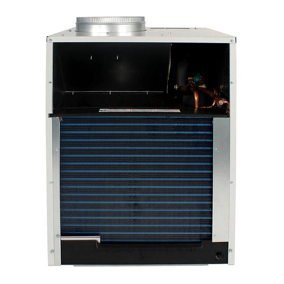
Single Package Vertical Air Conditioning System
L Suffix Models
V(E, H)A09K25L-*
V(E, H)A12K25L-*
V(E, H)A18K25L-*
V(E, H)A24K25L-*
V(E, H)A24K75L-*
VPK-ServMan-L (1-10)
A Series (Electronic Controls)
V(E, H)A09K34L-*
V(E, H)A12K34L-*
V(E, H)A18K34L-*
V(E, H)A24K34L-*
V(E, H)A24K10L-*
V(E, H)A09K50L-*
V(E, H)A12K50L-*
V(E, H)A18K25L-*
V(E, H)A24K50L-*
*Last Digit May Vary
Advertisement
Table of Contents
Troubleshooting

Related Manuals for Friedrich H)A09K25L


Summary of Contents for Friedrich H)A09K25L
- Page 1 S e r v i c e M a n u a l – R 4 1 0 A M o d e l s Single Package Vertical Air Conditioning System L Suffix Models V(E, H)A09K25L-* V(E, H)A12K25L-* V(E, H)A18K25L-*...
- Page 2 (See Unit Identification.) TECHNICAL SUPPORT CONTACT INFORMATION FRIEDRICH AIR CONDITIONING CO. Post Office Box 1540 · San Antonio, Texas 78295-1540 4200 N. Pan Am Expressway · San Antonio, Texas 78218-5212 (210) 357-4400 · 1-800-541-6645 · FAX (210) 357-4490 www.friedrich.com...
-
Page 3: Table Of Contents
Important Safety Information ... Introduction ... Vert-I-Pak Model Number Identification Guide ... Serial Number Identification Guide ... Chassis Specifications ... Extended Cooling Performance ... Electrical Requirements ... Remote Thermostat and Low Voltage Control ... V-PAK Electronic Control Board Features ... Electronic Control Configuration ... -
Page 4: Important Safety Information
IMPORTANT SAFETY INFORMATION The information contained in this manual is intended for use by a qualified service technician who is familiar with the safety procedures required for installation and repair, and who is equipped with the proper tools and test instruments required to service this product. Installation or repairs made by unqualified persons can result in subjecting the unqualified person making such repairs as well as the persons being served by the equipment to hazards resulting in injury or electrical shock which can be serious or even fatal. - Page 5 • Never operate the A/C unit with wet hands. • Use air conditioner on a single dedicated circuit within the specified amperage rating. • Use on a properly grounded outlet only. •...
-
Page 6: Introduction
Failure to follow these instructions can result in fire and minor to serious property damage. WATER DAMAGE HAZARDS: • Improper installation maintenance, or servicing of the air conditioner unit, or not following the above Safety Warnings can result in water damage to personal items or property. •... -
Page 7: Vert-I-Pak Model Number Identification Guide
MODEL NUMBER SERIES V=Vertical Series E=Cooling with or without electric heat H=Heat Pump DESIGN SERIES A = 32" and 47" Cabinet NOMINAL CAPACITY A-Series (Btu/h) 09 = 9,000 12 = 12,000 18 = 18,000 24 = 24,000 VOLTAGE K = 208/230V-1Ph-60Hz VPAK Serial Number Identification Guide SERIAL NUMBER YEAR MANUFACTURED... -
Page 8: Chassis Specifications
Chassis Specifications Model 2010 VEA09K COOLING DATA COOLING BTUh 9400/9000 POWER (W) SENSIBLE HEAT RATIO 0.74 HEAT PUMP DATA HEATING BTUh COP @ 47F HEATING POWER (W) ELECTRICAL DATA VOLTAGE 230/208 (1 PHASE, 60 Hz) VOLT RANGE 253-198 COOLING CURRENT (A) 4.2/4.4 AMPS L.R. -
Page 9: Extended Cooling Performance
Extended Cooling Performance VEA - EXTENDED COOLING PERFORMANCE BTUh 11054 10631 9842 10528 9926 WATTS VEA09 AMPS 0.51 0.69 BTUh 13524 13007 12041 12880 12144 11201 12374 11500 10178 11592 10293 9074 10954 9585 WATTS VEA12 AMPS 0.49 0.67 BTUh 19992 19227 17799 19040 17952 16558 18292 17000 15045 17136 15215 13413 16193 14170 12504 WATTS 1541... -
Page 10: Electrical Requirements
WARNING ELECTRIC SHOCK HAZARD Turn off electric power before service or instal- lation. All electrical connnections and wiring MUST be installed by a qualified electrician and conform to the National Electrical Code and all local codes which have jurisdiction. Failure to do so can result in personal injury and/or death. -
Page 11: Remote Thermostat And Low Voltage Control
CONNeCTIONs RT5 (Two speed fan) Remote Thermostat All Friedrich Vert-I-Pak units are factory configured to be controlled by using a 24V single stage remote wall mounted thermostat. The thermostat may be auto or manual changeover as long as the control configuration matches that of the Vert-I-Pak unit. - Page 12 210-357-4400. Desk Control Terminals The Friedrich VERT-I-PAK has built-in provisions for connection to an external switch to control power to the unit. The switch can be a central desk control system or even a normally open door switch.
-
Page 13: V-Pak Electronic Control Board Features
CONTROL BOARD FeATURes The new Friedrich Vert-I-Pak has state of the art features to improve guest comfort and conserve energy. Through the use of specifically designed control software, Friedrich has accomplished what other Manufacturer’s have only attempted – a quiet, dependable, affordable and easy to use Vert-I-Pak. -
Page 14: Electronic Control Configuration
Electronic Control Configuration The adjustable control dip switches are located at the lower left hand portion of the digital Smart Center. The inputs are only visible and accessible with the front cover removed from the Unit. Factory Dip Switch Configuration Dip Switch Setting Switches 1-4 ON Switch 5-7 OFF... -
Page 15: Electronic Control Error Code Diagnostics/Test Mode
electronic Control error Code Diagnostics Error Code Extreme low voltage condition exists (<198V for 230V units and <239V for 265V units). Return air thermistor sensor open or short circuit Indoor coil thermistor sensor open or short circuit Outdoor coil thermistor sensor open or short circuit Outdoor coil Temperature >... -
Page 16: Electronic Control Features
VPAk eLeCTRONIC CONTROL FeATURes Thermostat Compatibility: The VPAK Electronic Control is compatible with Friedrich RT4 and RT5 Thermostats. The VPAK Electronic control is also compatible with most standard Single Stage Heat/Cool Thermostats. NOTE: Field supplied Thermostats MUST energize the fan circuit on a call for Heating or Cooling, and (when used with a Heat Pump Unit) MUST energize the “B”... -
Page 17: Checking External Static Pressure
External Static Pressure External Static Pressure can best be defi ned as the pressure difference (drop) between the Positive Pressure (discharge) and the Negative Pressure (intake) sides of the blower. External Static Pressure is developed by the blower as a result of resistance to airfl... -
Page 18: Checking Approximate Airflow
Correct CFM (if needed): Chart B – Correction Multipli Explanation of charts Chart A is the nominal dry coil VERT-I-PAK CFMs. Chart B is the correction factors beyond nominal conditions. 1 ½ TON SYSTEM ( 18,000 Btu) Operating on high speed @ 230 volts with dry coil measured external static pressure .10 Air Flow = 450 CFM In the same SYSTEM used in the previous example but... -
Page 19: Components Testing
COMPONeNTs TesTINg BLOWER / FAN MOTOR A single phase permanent split capacitor motor is used to drive the evaporator blower and condenser fan. A self-resetting overload is located inside the motor to protect against high temperature and high amperage conditions. WARNING ELECTRIC SHOCK HAZARD Disconnect power to the unit before... - Page 20 COMPONeNTs TesTINg (Continued) HEATER ELEMENTS AND LIMIT SWITCHES’ SPECIFICATIONS All heat pumps and electric heat models are equipped with a heating element and a limit switch (bimetal ther- mostat). The limit is in series with the element and will interrupt the power at a designed temperature. Should the blower motor fail, filter become clogged or air- flow be restricted etc., the high limit switch will open and interrupt the power to the heater before reaching an un-...
-
Page 21: Refrigeration Sequence Of Operation
ReFRIgeRATION seQUeNCe OF OPeRATION A good understanding of the basic operation of the refrigeration system is essential for the service technician. Without this understanding, accurate troubleshooting of refrigeration system problems will be more difficult and time consuming, if not (in some cases) entirely impossible. The refrigeration system uses four basic principles (laws) in its operation they are as follows: 1. -
Page 22: Service
seRVICe WARNING ELECTRIC SHOCK HAZARD Turn off electric power before service or installation. Extreme care must be used, if it becomes necessary to work on equipment with power applied. Failure to do so could result in serious injury or death. CAUTION CUT/SEVER HAZARD Be careful with the sharp edges and corners. -
Page 23: Sealed Refrigeration System Repairs
seALeD ReFRIgeRATION sYsTeM RePAIRs ANY SEALED SYSTEM REPAIRS TO COOL-ONLY MODELS REQUIRE THE INSTALLATION OF A LIQUID LINE DRIER. ALSO, ANY SEALED SYSTEM REPAIRS TO HEAT PUMP MODELS REQUIRE THE INSTALLATION OF A SUCTION LINE DRIER. EQUIPMENT REQUIRED: 1. Voltmeter 2. -
Page 24: Method Of Charging
Method Of Charging / Repairs The acceptable method for charging the RAC system is the Weighed in Charge Method. The weighed in charge method is applicable to all units. It is the preferred method to use, as it is the most accurate. The weighed in method should always be used whenever a charge is removed from a unit such as for a leak repair, compressor replacement, or when there is no refrigerant... -
Page 25: Overcharged Refrigerant Systems
After the unit has run 10 to 15 minutes, check the gauge pressures. Gauges connected to system with an undercharge will have low head pressures and substantially low suction pressures. Overcharged Refrigerant systems Compressor amps will be near normal or higher. Noncondensables can also cause these symptoms. -
Page 26: Capillary Tube Systems/Check Valve
heRMeTIC COMPONeNTs CheCk WARNING BURN HAZARD Proper safety procedures must be followed, and proper protective clothing must be worn when working with a torch. Failure to follow these procedures could result in moderate or serious injury. MeTeRINg DeVICe Capillary Tube systems All units are equipped with capillary tube metering devices. -
Page 27: Reversing Valve Description/Operation
ReVeRsINg VALVe DesCRIPTION/OPeRATION WARNING ELECTRIC SHOCK HAZARD Disconnect power to the unit before servicing. Failure to follow this warning could result in serious injury or death. The Reversing Valve controls the direction of refrigerant flow to the indoor and outdoor coils. It consists of a pressure- operated, main valve and a pilot valve actuated by a solenoid plunger. -
Page 28: Reversing Valve
When sluggish or stuck in the mid-position, part of the discharge gas from the compressor is directed back to the suction side, resulting in excessively high suction pressure. Should the valve fail to shift from coooling to heating, block the air flow through the outdoor coil and allow the discharge pressure to build in the system. -
Page 29: Compressor Checks
6. Protect new valve body from heat while brazing with plastic heat sink (Thermo Trap) or wrap valve body with wet rag. Fit all lines into new valve and braze lines into new valve. WARNING EXPLOSION HAZARD The use of nitrogen requires a pressure regulator. -
Page 30: External Overload
WARNING BURN HAZARD Certain unit components operate at temperatures hot enough to cause burns. Proper safety procedures must be followed, and proper protective clothing must be worn. Failure to follow this warning could result in moderate to serious injury. external Overload VPAk 9, 12, 18 k Btus With power off, remove the leads from compressor termi- nals. -
Page 31: Compressor Replacement
COMPRessOR RePLACeMeNT Recommended procedure for compressor replacement WARNING RISK OF ELECTRIC SHOCK Unplug and/or disconnect all electrical power to the unit before performing inspections, maintenances or service. Failure to do so could result in electric shock, serious injury or death. Be certain to perform all necessary electrical and refrigeration tests to be sure the compressor is actually defective before replacing. -
Page 32: Routine Maintenance
SPECIAL PROCEDURE IN THE CASE OF MOTOR COMPRESSOR BURNOUT WARNING ELECTRIC SHOCK HAZARD Turn off electric power before service or installation. Failure to do so may result in personal injury, or death. WARNING HIGH PRESSURE HAZARD Sealed Refrigeration System contains refrigerant and oil under high pressure. -
Page 33: Electrical Troubleshooting Chart - Cooling
eLeCTRICAL TROUBLeshOOTINg ChART - COOLINg 9k BTU, 12k BTU, & 18k BTU Compressor runs but Fan runs but Blower/Fan doesn't Compressor doesn't Defective t-stat 24V at t-stat and defective control wiring control wiring? or transformer Problems indicated Is Line Voltage present in Blower Relay at Motor Leads? of board... -
Page 34: 2-Ton Electrical Troubleshooting Chart - Cooling
eLeCTRICAL TROUBLeshOOTINg ChART - COOLINg Compressor and outdoor Indoor blower runs but fan motor run but indoor outdoor fan motor and blower does not run compressor do not run 24V at t-stat and 24V at t-stat and defective control wiring control wiring? control wiring? Problems indicated... -
Page 35: Electrical Troubleshooting Chart Heat Pump
eLeCTRICAL TROUBLeshOOTINg ChART heAT PUMP HEAT PUMP MODE SYSTEM COOLS WHEN HEATING IS DESIRED. Is Line Voltage Present at Solenoid Valve? Is the Solenoid Coil Good? Reversing Valve Stuck Replace Reversing Valve Is Selector Switch set for Heat? Replace Solenoid Coil... -
Page 36: Refrigerant System Diagnosis Cooling
TROUBLeshOOTINg ChART - COOLINg REFRIGERANT SYSTEM DIAGNOSIS COOLING PROBLEM LOW SUCTION PRESSURE Low Load Conditions Low Air Flow Across Indoor Coil Refrigerant System Restriction Undercharged Moisture in System TROUBLeshOOTINg ChART - heATINg REFRIGERANT SYSTEM DIAGNOSIS HEATING PROBLEM LOW SUCTION PRESSURE Low Air Flow Across Outdoor Coil Refrigerant System... -
Page 37: Electrical And Thermostat Wiring Diagrams
COOL wITh eLeCTRIC heAT eLeCTRICAL & TheRMOsTAT wIRINg DIAgRAM VeA 09/12/18 with 2.5 kw, 3.4 kw or 5kw eLeCTRIC heAT NOTE: THE DIAGRAM ABOVE, ILLUSTRATES THE TYPICAL THERMOSTAT WIRING FOR TWO SPEED FAN OPERATION. SEE THE UNIT CONTROL PANEL FOR THE ACTUAL UNIT WIRING DIAGRAM AND SCHEMATIC. -
Page 38: Electric Heat
heAT PUMP wITh eLeCTRIC heAT eLeCTRICAL & TheRMOsTAT wIRINg DIAgRAM VhA 09/12/18 with 2.5 kw, 3.4 kw or 5kw eLeCTRIC heAT NOTE: THE DIAGRAM ABOVE, ILLUSTRATES THE TYPICAL THERMOSTAT WIRING FOR TWO SPEED FAN OPERATION. SEE THE UNIT CONTROL PANEL FOR THE ACTUAL UNIT WIRING DIAGRAM AND SCHEMATIC. - Page 39 COOL wITh eLeCTRIC heAT eLeCTRICAL & TheRMOsTAT wIRINg DIAgRAM VeA 24 with 2.5 kw, 3.4 kw or 5kw eLeCTRIC heAT...
- Page 40 heAT PUMP wITh eLeCTRIC heAT eLeCTRICAL & TheRMOsTAT wIRINg DIAgRAM VhA 24 with 2.5 kw, 3.4 kw or 5kw eLeCTRIC heAT...
- Page 41 COOL wITh eLeCTRIC heAT eLeCTRICAL & TheRMOsTAT wIRINg DIAgRAM VeA 24 with 7.5 kw and 10 kw eLeCTRIC heAT...
-
Page 42: Electrical And Thermostat Wiring Diagrams
heAT PUMP wITh eLeCTRIC heAT eLeCTRICAL & TheRMOsTAT wIRINg DIAgRAM VhA 24 with 7.5 kw and 10kw eLeCTRIC heAT... -
Page 43: Technical Service Data
TeChNICAL seRVICe DATA INDOOR COIL ELECTRICAL TEMPERATURE RATINGS SERVICE DATA º F Cooling¹ Temperature Voltage Amps Supply Air VEA09K**RTL 230/208 VEA12K**RTL 230/208 VEA18K**RTL 230/208 VEA24K**RTL 230/208 10.0 VHA09K**RTL 230/208 VHA12K**RTL 230/208 VHA18K**RTL 230/208 VHA24K**RTL 230/208 10.6 ¹Test Conditions: 80º F, Room Air Temperature with 50% Relative Humidity, and 95º F, Outdoor Air Temperature with 40% Relative Humidity **Denotes Heater KW - Numbers Vary TECHNICAL SERVICE DATA OUTDOOR COIL... - Page 44 TECHNICAL SUPPORT CONTACT INFORMATION FRIEDRICH AIR CONDITIONING CO. Post Office Box 1540 · San Antonio, Texas 78295-1540 4200 N. Pan Am Expressway · San Antonio, Texas 78218-5212 (210) 357-4400 · 1-800-541-6645 · FAX (210) 357-4490 www.friedrich.com Printed in the U.S.A.
- Page 45 FRIEDRICH AIR CONDITIONING CO. Post Office Box 1540 · San Antonio, Texas 78295-1540 4200 N. Pan Am Expressway · San Antonio, Texas 78218-5212 (210) 357-4400 · FAX (210) 357-4490 www.friedrich.com Printed in the U.S.A. VPK-ServMan-L (1-10)