Table of Contents
Advertisement
Quick Links
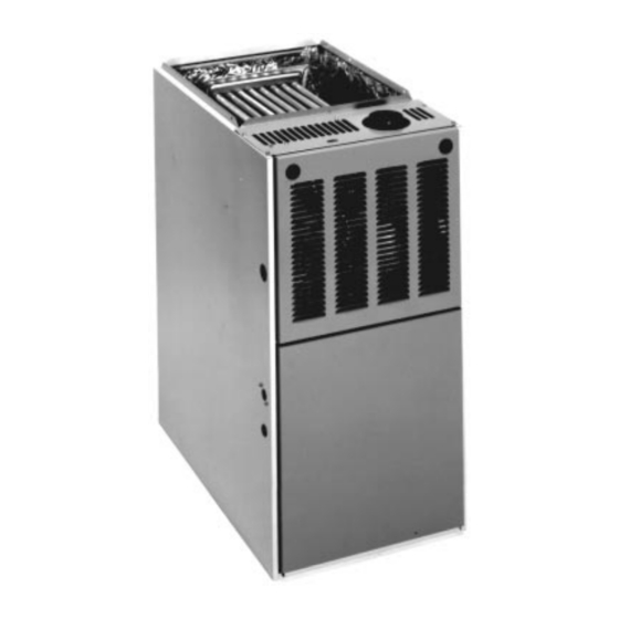
INSTALLATION INSTRUCTIONS
FOR UPFLOW/HORIZONTAL (RGPK) AND DOWNFLOW
(RGLK) TWO STAGE INDUCED DRAFT GAS FURNACES
!
Recognize this symbol as an indication of Important Safety Information!
WARNING
!
If the information in these instructions is not followed exactly, a
fire or explosion may result, causing property damage, personal
injury or death.
WARNING
!
PROPOSITION 65: THIS FURNACE CONTAINS FIBERGLASS
INSULATION. RESPIRABLE PARTICLES OF FIBERGLASS ARE
KNOWN TO THE STATE OF CALIFORNIA TO CAUSE CANCER.
EXHAUST GAS FROM THIS FURNACE CONTAINS CHEMICALS,
INCLUDING CARBON MONOXIDE, KNOWN TO THE STATE OF
CALIFORNIA TO CAUSE BIRTH DEFECTS OR OTHER REPRO-
DUCTIVE HARM.
WARNING
!
THESE INSTRUCTIONS ARE
INTENDED AS AN AID TO
QUALIFIED SERVICE
PERSONNEL FOR PROPER
INSTALLATION, ADJUSTMENT
AND OPERATION OF THIS
UNIT. READ THESE
INSTRUCTIONS THOROUGHLY
BEFORE ATTEMPTING
INSTALLATION OR
OPERATION. FAILURE TO
FOLLOW THESE
INSTRUCTIONS MAY RESULT
IN IMPROPER INSTALLATION,
ADJUSTMENT, SERVICE OR
MAINTENANCE, POSSIBLY
RESULTING IN FIRE,
ELECTRICAL SHOCK, CARBON
MONOXIDE POISONING,
EXPLOSION, PROPERTY
DAMAGE, PERSONAL INJURY
OR DEATH.
Do Not Destroy this Manual.
Please read carefully and keep
in a safe place for future
reference by a serviceman.
FOR YOUR SAFETY
!
— Do not store or use gasoline or other
flammable vapors and liquids, or other
combustible materials in the vicinity of this
or any other appliance.
— WHAT TO DO IF YOU SMELL GAS
• Do not try to light any appliance.
• Do not touch any electrical switch; do not
use any phone in your building.
• Immediately call your gas supplier from a
neighbor's phone. Follow the gas
supplier's instructions.
• If you cannot reach your gas supplier,
call the fire department.
• Do not return to your home until
authorized by the gas supplier or fire
department.
— DO NOT RELY ON SMELL ALONE TO
DETECT LEAKS. DUE TO VARIOUS
FACTORS, YOU MAY NOT BE ABLE TO
SMELL FUEL GASES.
• U.L. recognized fuel gas and CO
detectors are recommended in all
applications, and their installation should
be in accordance with the manufacturer's
recommendations and/or local laws,
rules, regulations, or customs
— Improper installation, adjustment, alteration,
service or maintenance can cause injury,
property damage or death. Refer to this
manual. Installation and service must be
performed by a qualified installer, service
agency or the gas supplier.
92-23531-88-00
Advertisement
Table of Contents

Related Manuals for Rheem RGPK


Summary of Contents for Rheem RGPK
-
Page 1: Safety Precautions
INSTALLATION INSTRUCTIONS FOR UPFLOW/HORIZONTAL (RGPK) AND DOWNFLOW (RGLK) TWO STAGE INDUCED DRAFT GAS FURNACES Recognize this symbol as an indication of Important Safety Information! WARNING If the information in these instructions is not followed exactly, a fire or explosion may result, causing property damage, personal injury or death. -
Page 2: Installation Check List
Before beginning any troubleshooting procedure, complete the following installation checklist. A furnace malfunction is sometimes caused by an improper installation. By completing this checklist, the problem may be found and corrected. Make copies of the checklist and complete one for every Low Profile Furnace service call for your records. INSTALLATION CHECKLIST (Refer to this manual for specifics.) GAS SUPPLY... -
Page 3: Table Of Contents
CONTENTS Safety Precautions ....................1 Installation Check List ....................2 Location Requirements and Considerations ............4 Combustion and Ventilation Air................10 Vent Pipe Installation....................13 Gas Supply and Piping...................16 Electrical Wiring......................19 Accessories ......................20 Air Flow........................26 Maintenance......................29 Troubleshooting......................31 Wiring Diagram.......................34 Installation Instructions are updated on a regular basis. This is done as product changes occur or if new information becomes available. -
Page 4: Location Requirements And Considerations
GENERAL INFORMATION The RGPK and RGLK series two stage This furnace should be installed in Installation of Air Conditioning and furnaces are designed certified to accordance with the American National Ventilating Systems 1985 or latest operate at full input and at 70% of full Standard Z223.1 - latest edition booklet... - Page 5 ⁄ CLEARANCE TO COMBUSTIBLE MATERIAL (INCHES) BOTTOM UPFLOW AND UPFLOW/HORIZONTAL MODELS REDUCED CLEARANCE (IN.) Left Right Ship. Model Back Front Vent Side Side Wgts. ⁄ ⁄ ⁄ 85 lbs. ⁄ ⁄ ⁄ 105 lbs. ⁄ ⁄ ⁄ ⁄ ⁄ 10(A) 115 lbs.
- Page 6 CLEARANCE TO COMBUSTIBLE MATERIAL (INCHES) DOWNFLOW MODELS REDUCED CLEARANCE (IN.) Left Right Ship. BOTTOM Model Back Front Vent Side Side Wgts. ⁄ ⁄ ⁄ 85 lbs. ⁄ ⁄ ⁄ ⁄ 105 lbs. ⁄ ⁄ ⁄ ⁄ 10(A) 115 lbs. ⁄ ⁄...
- Page 7 CLEARANCE TO COMBUSTIBLE MATERIAL (INCHES) HORIZONTAL “ONLY” MODELS REDUCED CLEARANCE (IN.) Left Right Ship. Model Back Front Vent Side Side Wgts. ⁄ ⁄ ⁄ 85 lbs. ⁄ TOP VIEW ⁄ ⁄ ⁄ 105 lbs. 10(A) ⁄ ⁄ ⁄ 115 lbs. ⁄...
- Page 8 EXPLOSION OR FIRE RESULTING IN NEVER USE A DOOR AS A PART OF TABLE 1 PROPERTY DAMAGE, PERSONAL THE RETURN AIR PLENUM. THE FURNACE BASE BASE INJURY OR DEATH. THE FLOOR OR PLATFORM MUST WIDTH PLATE NO. PLATE SIZE HOMEOWNER SHOULD BE PROVIDE SOUND PHYSICAL ⁄...
- Page 9 NUMBER MUST BE IN PLACE DOWNFLOW UNITS 6. Be sure to have adequate space WHEN THE FURNACE IS for the unit filter. 1. Position the unit to minimize long INSTALLED WITH SIDE OR REAR NOTE: DO NOT take return air from runs or runs with many turns and AIR RETURN DUCTS.
-
Page 10: Combustion And Ventilation Air
Exposure to the following substances FIGURE 5 in the combustion air supply may also HORIZONTAL RETURN AIR DUCT require OUTDOOR AIR for combustion: • Permanent wave solutions • Chlorinated waxes and cleaners • Chlorine-based swimming pool chemicals • Water softening chemicals •... - Page 11 Combustion air must be free of acid FIGURE 7 forming chemicals; such as sulphur, AIR FROM ATTIC/CRAWL SPACE fluorine and chlorine. These elements are found in aerosol sprays, detergents, bleaches, cleaning solvents, air fresheners, paint and varnish removers, refrigerants and many other commercial and household products.
- Page 12 FIGURE 8 OUTSIDE AIR USING A HORIZONTAL INLET & OUTLET CONSULT LOCAL CODES FOR b. Not less than the sum of the areas Btuh Free Area Round Pipe Input Each Opening Size SPECIAL REQUIREMENTS. of all vent connectors in the confined space.
-
Page 13: Vent Pipe Installation
VENTING FIGURE 9 ATTACHING TO DRAFT INDUCER COLLAR GENERAL INFORMATION Vent the furnace in accordance with these instructions, National Fuel Gas Code, ANSI Z223.1 and/or the Natural Gas Installation Code, CAN/CGA- B149.1 & .2 and requirements or codes of the local utility or other authority having jurisdiction. - Page 14 The entire length of the vent FIGURE 10 connector shall be readily TYPICAL VENTING WITH “B-1” VENT accessible for inspection, cleaning and replacement. “B-1” VERTICAL VENTING Install type “B-1” vents in accordance with the terms of their listings and the vent manufacturer’s instructions.
- Page 15 FIGURE 11 DEDICATED VENTING THROUGH CHIMNEY WITH “B-1” VENT EXISTING VENT SYSTEMS 3. Insofar as is practical, close all 6. After it has been determined that each appliance that remains building doors, windows and all IMPORTANT RETROFIT connected to the common venting doors between the space where the VENTING INSTRUCTIONS system properly vents (when tested...
-
Page 16: Gas Supply And Piping
GAS SUPPLY AND PIPING GAS SUPPLY FIGURE 12 GAS PIPING INSTALLATION WARNING UPFLOW & DOWNFLOW THIS FURNACE IS EQUIPPED AT MANUAL GAS UNION THE FACTORY FOR USE ON VALVE NATURAL GAS ONLY. CONVER- GAS VALVE SION TO LP GAS REQUIRES A SPECIAL KIT SUPPLIED BY THE DISTRIBUTOR OR MANU- FACTURER. - Page 17 SETTING GAS PRESSURE The maximum gas supply pressure 4. Note or adjust the line gas WARNING to the furnace should be 10.5 w.c. pressure to give: NEVER PURGE A GAS LINE INTO natural gas, or 13 w.c. LP gas. The A.
- Page 18 LP CONVERSION ORIFICE SIZING CHART RATING PLATE ELEVATION The gas valve is not field convertible for INPUT use with LP gas. LP conversion kit no. BTU/HR 0 TO 7,999 FT. 8,000 FT. AND ABOVE RXGJ-FP09 is required. The kit HEATING VALUE @ 1,000 BTU/FT , SPECIFIC GRAVITY 0.62 includes a LP gas valve, burner orifices NATURAL GAS...
-
Page 19: Electrical Wiring
ELECTRICAL WIRING FIGURE 14 ISOLATION RELAY WARNING TURN OFF ELECTRIC POWER AT THE FUSE BOX OR SERVICE PANEL BEFORE MAKING ANY ELECTRICAL CONNECTIONS. ALSO, THE GROUND CONNECTION MUST BE COMPLETED BEFORE MAKING LINE VOLTAGE CONNECTIONS. FAILURE TO DO SO CAN RESULT IN ELECTRICAL SHOCK, SEVERE PERSONAL INJURY OR DEATH. -
Page 20: Accessories
FIGURE 15 LINE VOLTAGE CONNECTIONS UTEC 1095-100 CONTROL BOARD ST-A0761-01 FIELD INSTALLED OPTION FURNACE TWINNING ACCESSORIES INSTALLATIONS HIGH ALTITUDE KIT ELECTRONIC AIR CLEANER Twinning operation of two furnaces, 1. Electronic air cleaner line voltage installed side-by-side, connected by a Models with inputs over 50,000 btu/hr power can be supplied from the common duct system with main power installed at altitudes of 5,000 feet and... - Page 21 FIGURE 16 UTEC NO. 1095-100 CONTROL BOARD TWINNING CONNECTION SINGLE STAGE OPERATION I685...
- Page 22 FIGURE 17 UTEC NO. 1095-100 CONTROL BOARD TWINNING CONNECTION TWO STAGE OPERATION I684...
- Page 23 DIRECT SPARK IGNITION b. When there is a call for heat, the “R” c. To reset the lockout, make and and “W2” contacts close and the IFC break power either at the thermostat LIGHTING INSTRUCTIONS runs a self check routine to verify or at the unit disconnect switch for 5 that the pressure switch contacts to 10 seconds.
- Page 24 FAN CONTROL GAS FURNACE (DIRECT Reconnect the unused lead to the M1 or M2 terminal. Check motor lead for DRIVE) INSTRUCTIONS FOR The furnace is equipped with an speed designation. Do not reduce the CHANGING BLOWER SPEED integrated furnace control which heating speeds where it could cause automatically starts the main blower 30 the furnace air temperature rise to...
- Page 25 A properly calibrated manometer or ORIFICE SIZING CHART gauge is required for accurate gas RATING PLATE ELEVATION pressure readings. INPUT BTU/HR 0 TO 7,999 FT. 8,000 FT. AND ABOVE 1. When adjusting the furnace input, the high fire input should be HEATING VALUE @ 1,000 BTU/FT , SPECIFIC GRAVITY 0.62 checked.
-
Page 26: Air Flow
AIR FLOW FIGURE 20 TEMPERATURE RISE MEASUREMENT The importance of proper air flow over the heat exchanger cannot be over emphasized. One of the most common causes of heat exchanger failure is overheating due to low air flow. An air flow table is located inside the blower door and on the following pages. - Page 27 BLOWER PERFORMANCE DATA – RGPK UPFLOW/HORIZONTAL MODELS CFM AIR DELIVERY BLOWER MOTOR BLOWER EXTERNAL STATIC PRESSURE INCHES WATER COLUMN MODEL (BTU) SIZE H.P. SPEED MED-LO 50,000 11 x 6 MED-HI 1115 1090 1070 1040 1015 1270 1250 1225 1200 1165...
- Page 28 LUBRICATION FIGURE 22 The blower motor and induced draft DOWNFLOW BLOWER REMOVAL motor are permanently lubricated by the manufacturer and do not require further attention. The motor must be cleaned periodically by a qualified installer, service agency, or the gas supplier to prevent the possibility of overheating due to an accumulation of dust and dirt on the windings or on the motor...
-
Page 29: Maintenance
MAINTENANCE FIGURE 23 RESIZING FILTERS & FRAME WARNING DISCONNECT MAIN ELECTRICAL POWER TO THE UNIT BEFORE ATTEMPTING ANY MAINTENANCE. FAILURE TO DO SO CAN CAUSE ELECTRICAL SHOCK RESULTING IN SEVERE PERSONAL INJURY OR DEATH. FILTERS Keep the air filters clean at all times. Vacuum dirt from filter, wash with detergent and water, air dry thoroughly and reinstall. - Page 30 FIGURE 25 FILTER RETAINING RODS (SIDE RETURN) FIGURE 26 DOWNFLOW FILTER INSTALLATION...
-
Page 31: Troubleshooting
IMPORTANT: Do not operate the 12. Flush each heat exchanger tube WARNING system for extended periods without with water from a hose and blow HOLES IN THE VENT PIPE OR HEAT filters. A portion of the dust entrained out with air to remove excessive EXCHANGER CAN CAUSE TOXIC in the air may temporarily lodge in the moisture. - Page 32 FIGURE 27 INTEGRATED FURNACE CONTROL (IFC) TROUBLESHOOTING GUIDE FOR UTEC 1095-100...
- Page 34 FIGURE 28 UTEC 1095-100 INTEGRATED FURNACE CONTROL...
- Page 36 Rheem Manufacturing Company Air Conditioning Division CM 997 Fort Smith, Arkansas...