Lochinvar Knight XL 100 Series Installation & Operation Manual
Hide thumbs
Also See for Knight XL 100 Series:
- User's information manual (12 pages) ,
- Service manual (52 pages)
Table of Contents
Advertisement
100329949_2000586636_Rev F
Installation & Operation Manual
Models: 400 - 1000
Series 100 & 101
⚠ WARNING
This manual must only be used
by a qualified heating installer
/ service technician. Read all
instructions,
manual and the Knight XL
Service Manual, before installing.
Perform steps in the order given.
Failure to comply could result in
severe personal injury, death, or
substantial property damage.
Save this manual for future reference.
including
this
Advertisement
Table of Contents

Related Manuals for Lochinvar Knight XL 100 Series


Summary of Contents for Lochinvar Knight XL 100 Series
- Page 1 100329949_2000586636_Rev F Installation & Operation Manual Models: 400 - 1000 Series 100 & 101 ⚠ WARNING This manual must only be used by a qualified heating installer / service technician. Read all instructions, including this manual and the Knight XL Service Manual, before installing.
-
Page 2: Table Of Contents
Contents 6. OUTDOOR INSTALLATIONS ....... 36-37 HAZARD DEFINITIONS ..........2 7. HYDRONIC PIPING PLEASE READ BEFORE PROCEEDING ..... 3 THE KNIGHT XL -- HOW IT WORKS ......4-6 System Water Piping Methods ......... 38 Low Water Cutoff Device ..........38 RATINGS ................ -
Page 3: Please Read Before Proceeding
Installation & Operation Manual Please read before proceeding The California Safe Drinking Water and ⚠ WARNING Installer – Read all instructions, including ⚠ WARNING Toxic Enforcement Act requires the this manual and the Knight XL Service Governor of California to publish a list of Manual, before installing. -
Page 4: The Knight Xl - How It Works
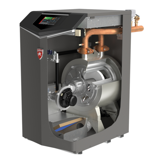
Installation & Operation Manual The Knight XL - How it works... 1. Stainless steel heat exchanger 19. Boiler drain port Allows system water to flow through specially designed Location from which the heat exchanger can be drained. coils for maximum heat transfer, while providing protection 20. - Page 5 Installation & Operation Manual The Knight XL - How it works... (continued) Model 400 - 500 Front View - Model 400 Rear View - Model 400 Left Side (inside unit) - Model 400 Right Side (inside unit) - Model 400...
- Page 6 Installation & Operation Manual The Knight XL - How it works... Model 650 - 1000 DIR #2000582923 DIR #2000582923 DIR #2000582923 DIR #2000582924 Front View - Model 1000 Left Side (inside unit) - Model 1000 DIR #2000582937 DIR #2000582932 Rear View - Model 1000 Left Side (inside unit) - Model 1000...
-
Page 7: Ratings
Installation & Operation Manual Ratings Knight XL Boiler Other Specifications AHRI Rating Input Model Number Gross AHRI Boiler Output Ratings Water Water Vent Size Water, (Note 2) Content Connections Connections Size Note: Change “N” to Gallons “L” for L.P. gas models. (Note 1) (Note 2) (Note 3) -
Page 8: Determine Boiler Location
Installation & Operation Manual Determine boiler location Installation must comply with: DO NOT install the boiler in a room likely to freeze. • Local, state, provincial, and national codes, laws, Unless specified as an outdoor boiler, this ⚠ WARNING regulations, and ordinances. appliance is certified as an indoor appliance. - Page 9 Installation & Operation Manual Determine boiler location (continued) Figure 1-1 Closet Installation - Minimum Required Clearances For closet installations, CPVC, ⚠ WARNING polypropylene or stainless steel vent material MUST BE used in a closet structure due to elevated temperatures. Failure to follow this warning could result in fire, personal injury, or death.
-
Page 10: Provide Air Openings To Room
Installation & Operation Manual Determine boiler location Provide air openings to room: Residential garage installation Knight XL alone in boiler room Precautions Take the following precautions when installing the appliance 1. No air ventilation openings into the boiler room are in a residential garage. -
Page 11: Corrosive Contaminants And Sources
Installation & Operation Manual Determine boiler location (continued) Table 1A Corrosive Contaminants and Sources When using an existing vent system to install a new boiler: Products to avoid: Failure to follow all instructions can result ⚠ WARNING Spray cans containing chloro/fluorocarbons in flue gas spillage and carbon monoxide emissions, causing severe personal injury Permanent wave solutions... -
Page 12: Removing A Boiler From Existing Common Vent
Installation & Operation Manual Determine boiler location When removing a boiler from existing common vent system: Do not install the Knight XL into a ⚠ DANGER g. Any improper operation of the common venting common vent with any other appliance. system should be corrected so the installation conforms with the National Fuel Gas Code, ANSI Z223.1/ This will cause flue gas spillage or appliance... -
Page 13: Prepare Boiler
Installation & Operation Manual Prepare boiler Remove boiler from wood pallet Models 400-1000 (Venturi w/ LP Orifices) 1. Remove the front access panel from the unit (no tools 1. After removing the outer shipping carton from the boiler, required for removal). remove the parts box. - Page 14 Installation & Operation Manual Prepare boiler 10. For Models 400-500: Remove the front panel from the Figure 2-4 Gas Valve Adjustment - Models 650 - 1000 unit (no tools required for removal). COVER For Models 650-1000: Remove the top access cover from the unit (no tools required for removal).
-
Page 15: General Venting
Installation & Operation Manual General venting Direct venting options - Sidewall Vent DIR #2000583014 00 DIR #2000583013 00 Two Pipe Sidewall PVC/CPVC Concentric Sidewall Models 400 - 500 Only Direct venting options - Vertical Vent DIR #2000583016 00 DIR #2000583017 00 DIR #2000583015 00 Two Pipe Vertical PVC/CPVC... -
Page 16: Install Vent And Combustion Air Piping
Installation & Operation Manual General venting Install vent and combustion air piping The Knight XL boiler must be vented and ⚠ DANGER The Knight XL boiler vent and air piping can be installed supplied with combustion and ventilation through the roof or through a sidewall. Follow the procedures air as described in this section. -
Page 17: Requirements For Installation In Canada
45° elbow. material to comply with this requirement. The 4" Concentric Vent Kit available from Lochinvar (see EXAMPLE: 20 feet (6 m) of PVC pipe + (3) 90° elbows + Section 4 – Sidewall Termination – Optional Concentric (3) 45°... -
Page 18: Materials
Type “B” double-wall vent with joints and seams sealed as 3. Each Knight XL boiler must have a Lochinvar supplied flue specified in this section. damper installed (see Table 3E). AL29-4C, stainless steel material to be sealed to specification of its manufacturer. -
Page 19: Optional Room Air
Installation & Operation Manual General venting (continued) Common venting CAT II: Table 3G Optional Room Air Kit Flues of multiple appliances may be combined by incorporating a vent increaser to change the Category IV appliance to a Model Description Kit Number Category II vent system which can be common vented using 400 - 1000 90°... - Page 20 Installation & Operation Manual General venting Table 3H PVC/CPVC Vent Pipe and Fittings Dry fit vent or air piping to ensure proper fit up before assembling any joint. The pipe should go Approved PVC/CPVC Vent Pipe and Fittings a third to two-thirds into the fitting to ensure Item Material Standard...
-
Page 21: Polypropylene
Installation & Operation Manual General venting (continued) Polypropylene Installation of a polypropylene vent system NOTICE should adhere to the vent manufacturer’s This product has been approved for use with polypropylene installation instructions supplied with the vent with the manufacturers listed in Table 3H. vent system. -
Page 22: Stainless Steel Vent
Installation & Operation Manual General venting Stainless steel vent Figure 3-5 Near Boiler Stainless Steel Venting Models This product has been approved for use with stainless steel 400 - 1000 using the manufacturers listed in Table 3K. Use only the materials, vent systems, and ⚠... -
Page 23: Sidewall Direct Venting Vent/Air Termination - Sidewall
Installation & Operation Manual Sidewall direct venting Vent/air termination – sidewall Figure 4-1A PVC/CPVC/Polypropylene Sidewall Termination of Air and Vent Follow instructions below when ⚠ WARNING TO BOILER determining vent location to avoid INTAKE AIR CONNECTION possibility of severe personal injury, death, or substantial property damage. - Page 24 Installation & Operation Manual Sidewall direct venting Vent/air termination – sidewall Do not terminate closer than 4 feet (1.2 m) horizontally from any electric meter, gas meter, Figure 4-2A Alternate PVC/CPVC/ Polypropylene regulator, relief valve, or other equipment. Never Sidewall Termination w/Field Supplied Fittings terminate above or below any of these within 4 feet (1.2 m) horizontally.
-
Page 25: Prepare Wall Penetrations
Installation & Operation Manual Sidewall direct venting (continued) Vent/air termination – sidewall For Polypropylene Only: Install the vent and air intake Figure 4-4A Clearance to Forced Air Inlets sidewall adapters from Table 3H into the vent plate. Slide IF LESS the sidewall retaining bracket down the sidewall adapters THAN 10’... -
Page 26: Multiple Vent/Air Terminations
Installation & Operation Manual Sidewall direct venting Multiple vent/air terminations Figure 4-5B Polypropylene Sidewall Termination Assembly SIDEWALL 1. When terminating multiple Knight XL’s terminate ADAPTER each vent/air connection as described in this manual (AIR) WALL PLATE (FIG. 4-6A). SIDEWALL ⚠ WARNING All vent pipes and air inlets must terminate RETAINING PLATE... -
Page 27: Sidewall Termination - Optional Concentric Vent
Sidewall termination – optional concentric vent: Models 400 - 500 Only Description and usage Lochinvar offers an optional concentric combustion air 3. Cut one (1) hole 7 inch (178 mm) diameter for #100140484 and vent pipe termination kit (#100140484 for 4" (102 mm) installations into the structure to install the termination kit. - Page 28 Installation & Operation Manual Sidewall direct venting Sidewall termination – optional concentric vent: Models 400 - 500 Only Figure 4-9 Concentric Vent Dimensional Drawing - Models 400 - 500 "A" "B" DIA. "C" DIA. "D" 3" (76 MM) "E" "G" "H"...
- Page 29 Installation & Operation Manual Sidewall direct venting (continued) Sidewall termination – optional concentric vent: Models 400 - 500 Only Figure 4-11 Concentric Vent Sidewall Attachment STRAP (FIELD SUPPLIED) ELBOW (FIELD SUPPLIED) COMBUSTION AIR COMBUSTION AIR VENT VENT Multiventing sidewall terminations DO NOT use field-supplied couplings CAUTION to extend pipes.
-
Page 30: Vertical Direct Venting Vent/Air Termination - Vertical
Installation & Operation Manual Vertical direct venting Vent/air termination – vertical Follow instructions below when ⚠ WARNING Figure 5-1A PVC/CPVC/Polypropylene Vertical determining vent location to avoid Termination of Air and Vent possibility of severe personal injury, death or substantial property damage. ALTERNATE INTAKE LOCATIONS: INTAKE PIPES MAY BE LOCATED ANYWHERE WITHIN 24"... -
Page 31: Prepare Roof Penetrations
Installation & Operation Manual Vertical direct venting (continued) Vent/air termination – vertical Prepare roof penetrations Air pipe penetration: Cut a hole for the air pipe. Size the air pipe hole as Figure 5-2 Vertical Terminations with Multiple Boilers close as desired to the air pipe outside diameter. 12"... -
Page 32: Vertical Termination - Optional Concentric Vent
Description and usage 2. Cut one (1) hole (7 inch (178 mm) diameter for #100140484 Lochinvar offers an optional concentric combustion air and installations) into the structure to install the termination vent pipe termination kit. Both combustion air and vent kit. - Page 33 Installation & Operation Manual Vertical direct venting (continued) Vertical termination – optional concentric vent: Models 400 - 500 Only Do not operate the appliance with ⚠ WARNING DO NOT use field-supplied couplings CAUTION the rain cap removed or recirculation to extend pipes. Airflow restriction will of combustion products may occur.
-
Page 34: Alternate Vertical Concentric Venting
Installation & Operation Manual Vertical direct venting Alternate vertical concentric venting This appliance may be installed with a concentric vent Figure 5-8 Concentric Vent Example 1 arrangement where the vent pipe is routed through an existing unused venting system; or by using the existing FLUE EXHAUST unused venting system as a chase for vent and combustion air routing. - Page 35 Installation & Operation Manual Vertical direct venting (continued) Existing vent as a chase Follow all existing termination and clearance requirements and allowable pipe lengths. Use only approved venting materials listed in the General Venting Section of this manual. Figure 5-10 Existing Vent as a Chase AIR INLET FLUE EXHAUST SEAL...
-
Page 36: Outdoor Installations
Installation & Operation Manual Outdoor installations Outdoor venting Outdoor vent / air inlet location • In order to properly install the appliance in an outdoor Keep venting areas free of obstructions. Keep area clean and free configuration, the appropriate outdoor ready model (ex. of combustible and flammable materials. - Page 37 Installation & Operation Manual Outdoor installations (continued) Outdoor venting Before installing a venting system, follow all requirements found in the General Venting section. NOTICE Units are self-venting and can be used outdoors when installed with the optional outdoor kit. Combustion air supply must be free of contaminants (see Combustion and Ventilation Air, page 10). To prevent recirculation of the flue products into the combustion air inlet, follow all instructions in this section.
-
Page 38: Hydronic Piping
Installation & Operation Manual General piping information Hydronic piping All boiler piping must contain an oxygen IMPORTANT System water piping methods barrier. This will help prevent any excess oxygen from entering the system. The Knight XL is designed to function in a closed loop Basic steps are listed below along with illustrations on the pressurized system not less than 12 psi (83 kPa) (Non- following pages (FIG.’s 6-7 through 6-11), which will guide you... - Page 39 Installation & Operation Manual Hydronic piping (continued) A magnetic separator is recommended NOTICE when a unit is installed in a retrofit system or a system containing steel and/or cast iron pipe. See the piping illustrations included in this section, FIG.’s 7-4 thru 7-8 for suggested guidelines in piping the Knight XL.
-
Page 40: Near Boiler Piping Components
4 - 90° elbows, and 2 - fully ported ball valves. 13. System temperature sensor: 2. Boiler system circulating pump: Lochinvar supplies a system temperature sensor. The Field supplied. The boiler circulating pump should be sensor is to be installed in the heating loop downstream... -
Page 41: Circulator Sizing
To help aid with this protection, PRESSURE STRAINER / FILTER AIR SEPARATOR DRAIN PORT REDUCING VALVE Lochinvar offers the Multi- Temperature Loop Control LEGEND BACKFLOW PRESSURE RELIEF TEMPERATURE & EXPANSION TANK PREVENTER... - Page 42 Installation & Operation Manual Hydronic piping Figure 7-3 Pressure Drop vs. Flow PRESSURE DROP VS FLOW (HEAT EXCHANGER ONLY) 1000 FLOW RATE (GPM) Table 7A Sizing Information for Temperature Rise Applications_20°F, 25°F, 30°F and 35°F TEMPERATURE RISE APPLICATIONS 20°F 25°F 30°F 35°F MINIMUM...
- Page 43 Installation & Operation Manual Hydronic piping (continued) Figure 7-4 Single Boiler - Multiple Temperatures WIRES TO TEMP TEMP TEMP LOOP SENSORS LOOP 1 LOOP 2 LOOP 3 SENSOR 1 SENSOR 2 SENSOR 3 SENSOR 1 SENSOR 2 SENSOR 3 120VAC TO PUMPS PUMP 1 PUMP 2...
- Page 44 Installation & Operation Manual Hydronic piping Figure 7-5 Single Boiler - Primary/Secondary Piping MAY SUBTITUTE LOW LOSS HEADER FROM SYSTEM SYSTEM MAKE UP WATER NOT TO EXCEED 4 PIPE DIA OR MAX OF 12” APART INDIRECT DHW HOT WATER OUT BOILER TANK COLD...
- Page 45 Installation & Operation Manual Hydronic piping (continued) Figure 7-6 Multiple Boilers - Multiple Temperatures Number of Units Model Required Pipe Sizes in NPT (Based on 30°△) 1000 WIRES TO TEMP TEMP TEMP LOOP SENSORS LOOP 1 LOOP 2 LOOP 3 SENSOR 1 SENSOR 2 SENSOR 3...
- Page 46 Installation & Operation Manual Hydronic piping Figure 7-7 Multiple Boilers - Primary/Secondary Piping Number of Units Model Required Pipe Sizes in NPT (Based on 30°△) 1000 MAY SUBTITUTE LOW LOSS HEADER FROM SYSTEM SYSTEM MAKE UP NOT TO EXCEED 4 PIPE DIA OR WATER MAX OF 12”...
- Page 47 Installation & Operation Manual Hydronic piping (continued) Figure 7-8 Single Boiler - Multiple Temperatures with DHW Piped as a Zone WIRES TO TEMP TEMP TEMP LOOP SENSORS LOOP 1 LOOP 2 LOOP 3 SENSOR 1 SENSOR 2 SENSOR 3 SENSOR 1 SENSOR 2 SENSOR 3 120VAC...
-
Page 48: Gas Connections Connecting Gas Supply Piping
Installation & Operation Manual Gas connections Connecting gas supply piping 3. Support piping with hangers, not by the boiler or its accessories. 1. Remove the top access panel and refer to FIG.’s 8-1 thru The gas valve and blower will not support ⚠... -
Page 49: Natural Gas
Installation & Operation Manual Gas connections (continued) Natural gas: ⚠ WARNING Failure to apply pipe sealing compound as detailed in this manual can result Pipe sizing for natural gas in severe personal injury, death, or substantial property damage. 1. Refer to Table 8A for pipe length and diameter. Based on rated boiler input (divide by 1,000 to obtain cubic feet per Use two wrenches when tightening gas ⚠... -
Page 50: Check Inlet Gas Supply
Installation & Operation Manual Gas connections Table 8A Natural Gas Pipe Size Chart Capacity of Schedule 40 Metallic Pipe in Cubic Feet of Natural Gas Per Hour (based on .60 specific gravity, 0.30" w.c. pressure drop) Pipe Length of Pipe in Straight Feet Size (Inches) 1 1/4... -
Page 51: Gas Pressure
Installation & Operation Manual Gas connections (continued) When re-tightening the set screw, be sure ⚠ WARNING Figure 8-5 Inlet Gas Supply Check - Models 650 - 1000 to tighten securely to prevent gas leaks. Do not check for gas leaks with an open flame -- use the bubble test. -
Page 52: Field Wiring
Installation & Operation Manual Field wiring Installation must comply with: ELECTRICAL SHOCK HAZARD – For ⚠ WARNING your safety, turn off electrical power supply before making any electrical 1. National Electrical Code and any other national, state, connections to avoid possible electric provincial, or local codes, or regulations. - Page 53 Connect this The tank sensor included with the Lochinvar Squire® indirect output to the 0 - 10V input on the boiler pump speed control.
-
Page 54: Wiring Of The Cascade
Installation & Operation Manual Field wiring Modbus / BACnet Alarm contacts When the optional ModBus / BACnet interface module is The SMART TOUCH control closes another set of contacts installed, the RS-485 ModBus / BACnet cable is connected whenever the boiler is locked out or the power is turned off. to these terminals. - Page 55 Installation & Operation Manual Field wiring (continued) Figure 9-3 Low Voltage Field Wiring Connections...
-
Page 56: Condensate Disposal
Installation & Operation Manual Condensate disposal Condensate drain 1. This boiler is a high efficiency appliance that produces Use materials approved by the authority NOTICE condensate. having jurisdiction. In the absence of other authority, PVC and CPVC pipe must comply 2. -
Page 57: Start-Up
Installation & Operation Manual Start-up Pre-Commissioning Cleaning Boiler water 1. Prior to fill and start-up, flush the entire heating system. Do not use petroleum based cleaning or CAUTION sealing compounds in the boiler system. 2. Clean the entire heating system with an approved pre- Gaskets and seals in the system may be commissioning cleaner (comparable to Sentinel X300 damaged. - Page 58 Installation & Operation Manual Start-up Fill and test water system Use glycol only if needed for freeze protection fluid. Propylene glycol is the recommended freeze protection 1. Fill system only after ensuring the water meets the fluid. requirements of this manual. Make sure to flush the boiler system before adding glycol.
- Page 59 Installation & Operation Manual Start-up (continued) Check for gas leaks Propane boilers only – Your propane ⚠ WARNING supplier mixes an odorant with the propane Before starting the boiler, and during ⚠ WARNING to make its presence detectable. In some initial operation, smell near the floor and instances, the odorant can fade, and the around the boiler for gas odorant or any...
- Page 60 Installation & Operation Manual Start-up Condensate drain Use materials approved by the authority NOTICE having jurisdiction. In the absence of other 1. This boiler is a high efficiency appliance that produces authority, PVC and CPVC pipe must comply condensate. with ASTM D1785 or D2845. Cement and primer must comply with ASME D2564 or 2.
- Page 61 Installation & Operation Manual Start-up (continued) Final checks before starting the boiler q Check vent piping and air piping 1. Check for gastight seal at every connection, seam of air q Read the Knight XL Boiler Service Manual to familiarize piping, and vent piping.
- Page 62 Installation & Operation Manual Start-up Figure 11-2 Operating Instructions FOR YOUR SAFETY READ BEFORE OPERATING WARNING: If you do not follow these instructions exactly, a fire or explosion may result causing property damage, personal injury, or loss of life. • Immediately call your gas supplier from a A.
- Page 63 Installation & Operation Manual Start-up (continued) Check flame and combustion Set space heating operation (continued) Determine controlling sensor 4. Navigate to the Setup Screen from the Home Screen by pressing the SETUP button along the left side of the For space heating systems, the temperature control can be screen.
- Page 64 Installation & Operation Manual Start-up Adjust set point temperature(s) During normal operation, set point temperatures can be adjusted from the Home Screen by pressing the DETAILS button on the bottom of the screen (see FIG. 11-3). To change a set point, use the set point slider feature PLUS MINUS buttons...
- Page 65 DHW pump output, and raise the system temperature set point to the DHW boiler set Press the SETTINGS button under the Lochinvar logo (see point (if higher). The boiler pump will be turned on. The FIG.
- Page 66 Installation & Operation Manual Start-up Configuration of the cascade NOTE: The APPLY CHANGES button must be pressed to complete programming of the controls. Failure to press the NOTE: For more detailed instructions, please refer to the APPLY CHANGES button will result in an unprogrammed Knight XL Service Manual.
-
Page 67: Operating Information General
(3) separate loops, based on the settings for the three DHW is programmed for Zone Mode. It will continue to run (3) heat/loop demands (reference Lochinvar kit 100167843). for a short time after the end of the heat demand or the Freeze Protection Mode. - Page 68 Installation & Operation Manual Operating information Temperature control Protection features Modulation Outlet temperature, flue temperature, and temperature The Knight XL is capable of modulating its firing rate rise limiting from a minimum of 10% to a maximum of 100%. The firing rate is dictated by the call for heat (i.e., space heating The outlet temperature is monitored by the boiler outlet or domestic hot water), the heating load, ramp delay (if...
- Page 69 Installation & Operation Manual Operating information (continued) Error logging Freeze protection (continued) Neither this feature, the boiler control module, nor the use of The control will hold in memory the last 10 lockouts as well as glycol eliminates the possibility of freezing. The installation the last 10 blockings.
-
Page 70: Cascade
Installation & Operation Manual Operating information Low water cutoff protection Sequence of the cascade The SMART TOUCH control module uses temperature To equalize the run time of all boilers on the Cascade, the firing sensing of both supply and return areas of the heat sequence will automatically be changed at set intervals. -
Page 71: Sequence Of Operation
Installation & Operation Manual Operating information (continued) Sequence of operation OPERATION 1. Upon a call for heat, the gas pressure switch(es) must be closed. 2. Once the gas pressure switch(es) are closed, the control turns on the appropriate pumps (system and boiler pumps for space heating, DHW pump for DHW). -
Page 72: Knight Xl Control Module
(i.e. Off, screen. There are five (5) sections located below the Stand-by, Blocking, and Lockout) including: current Lochinvar icon: Home, View, Setup, Information driving demand, the next Hot Water Setback scheduled, (About), and Settings. The Home Section is the screen the reason for any blocking or lockout, and a power button. -
Page 73: Maintenance Maintenance And Annual Startup
Installation & Operation Manual Maintenance Maintenance and annual startup Table 13A Service and Maintenance Schedules Owner maintenance Service technician (see the Knight XL User’s Information Manual for (see the following pages for instructions) instructions) General: • Address reported problems • Inspect interior; clean and vacuum if •... - Page 74 Installation & Operation Manual Maintenance Follow the Service and maintenance procedures given throughout this manual and in component literature ⚠ WARNING shipped with the boiler. Failure to perform the service and maintenance could result in damage to the boiler or system. Failure to follow the directions in this manual and component literature could result in severe personal injury, death, or substantial property damage.
- Page 75 Installation & Operation Manual Maintenance (continued) Test boiler water Check all piping for leaks Eliminate all system or boiler leaks. ⚠ WARNING 1. Test boiler water. Reference the Knight XL Installation Continual fresh makeup water will and Operation Manual for guidelines. When test indicates, reduce boiler life.
- Page 76 Installation & Operation Manual Maintenance Inspect ignition and flame sense Figure 13-2 Burner Assembly - Model 400 - 1000 electrodes 1. Remove the ignition and flame sense electrodes from the boiler heat exchanger access cover. 2. Remove any deposits accumulated on the ignition/flame sense electrode using sandpaper.
- Page 77 Installation & Operation Manual Maintenance (continued) 6. Use a vacuum cleaner to remove any accumulation on the Check flame signal boiler heating surfaces. Do not use any solvent. 1. At high fire the flame signal shown on the display should 7.
-
Page 78: Diagrams
SHIELD COMMUNICATION LOUVER 0-10V CONTROL BOARD WIFI PROVING SWITCH DONGLE SYS PUMP CN5-4 X4-4 0-10V J3 J11 X5-2 Installation & Operation Manual BLR PUMP BLOCKED 0-10V X5-10 DRAIN SWITCH OPTIONAL USB/WIFI EXTENSION CABLE RATE 0-10V AIR PRESSURE X5-11 SWITCH OPTIONAL ETHERNET CABLE Diagrams SHIELD... -
Page 79: Ladder Diagram
Installation & Operation Manual Diagrams (continued) Figure 14-2 Ladder Diagram JUNCTION BOX 120VAC NEUTRAL TERMINAL STRIP TERMINAL STRIP 120V SUPPLY "L" 120V SUPPLY "N" BLOWER RELAY GROUND SYSTEM ON / OFF PUMP INTEGRATED CONTROL BLOWER SWITCH CONTACTS X1-1 X1-6 LOW VOLTAGE 120 VAC 3.15A BLOWER... -
Page 80: Revision Notes
Revision Notes: Revision A (TLA #3000042117 / CN #500030025) initial release. Revision B (PCP #3000042688 / CN # 500030426) reflects an update from SMART SYSTEM to SMART TOUCH. Revision C (PCP #3000043071 / CN #500030823) reflects an update to the high altitude verbiage.