Advertisement
Quick Links
Series Temperature Controller
Instruction Sheet
Thank you very much for choosing Delta DTE series temperature controller. Please read this instruction sheet carefully before
using your DTE to ensure proper operation. Keep this instruction sheet handy for quick reference.
Warning
DANGER! CAUTION! ELECTRIC SHOCK!
DTE is an OPEN-TYPE device and therefore should be installed in an enclosure free of airborne dust,
humidity, electric shock and vibration. The enclosure should prevent non-maintenance staff from
operating the device (e.g. key or specific tools are required for opening the enclosure) in case danger and
damage on the device may occur.
1. Prevent dust or metallic debris from falling into the device and cause malfunctions. DO NOT modify or uninstall the circuit
board of DTE without being permitted. DO NOT use empty terminals.
2. Keep away from high-voltage and high-frequency environment during the installation in case of interference. Prevent using
the device in premises which contain:
(a) dust or corrosive gas; (b) high humidity and high radiation; (c) shock and vibration.
3. The power has to be switched off when wiring or changing the temperature sensor.
4. When installing the circuit board of the accessory, please make sure the power of the main unit is switched off and insert
the accessory into the correct slot on the main unit.
5. Make sure to use compensation wire which matches the thermocouple or platinum resistance when extending or
connecting the thermocouple or platinum resistance.
6. Keep the wire as short as possible when wiring a sensor to the controller. Separate the power cable and load wire in order
to prevent interference and induced noise.
7. Make sure the power cables and signal device are installed correctly before switching on the power; otherwise serious
damage may occur.
8. DO NOT touch the terminal or repair the device when the power is on; otherwise an electric shock may occur.
9. Please wait for 1 minute after the power is switched off to allow the capacitor to discharge and DO NOT touch the internal
wiring within this period.
10. DO NOT touch the internal terminal when DTE is either switched on or off in case you may damage the circuit.
11. Please place DTE with other heating objects (e.g. power supply) within proper distance while installing DTE.
Ordering Information
Series name
DTE: Delta E series temperature controller
1
Device type
1: main unit
2: accessory
0T: 4-channel TC
0P: 4-channel PT
0V: 4 channels of voltage pulse output
0C: 4 channels of linear current output
0T: 4-channel TC
2
3
0P: 4-channel PT
0R: 4 channels of relay output
0L: 4 channels of linear voltage output
CT: 4 channels of current transformer sensors
DS: Display and setup module
Functions & Electrical Specifications
Power input
DC 24V, isolated switching power supply
Voltage range
90% ~ 110% rated voltage
Power consumption
Max. 10W + 3W × number of DTC2000 controllers connected in parallel (Max. 7)
Thermocouple: K, J, T, E, N, R, S, B, L, U, TXK
Input sensor
Platinum resistance: Pt100, JPt100, Cu50
Sampling cycle
Thermocouple or platinum resistance: 1.0 second/all input
Control method
PID, PID programmable, manual, ON/OFF
Relay output: SPST, Max. AC 250V load, 3A resistive load
Voltage pulse output: DC 24V, Max. 40mA current output
Output accessories
(optional)
Current output: DC 4 ~ 20mA output (resistive load < 500Ω); for OUT1 and OUT2 only
Analog voltage output: 0 ~ 10V (resistive load > 1,000Ω); for OUT1 and OUT2 only
Control output, alarm output or proportional output (proportional output is only applicable in
Output functions
the model with linear voltage and current output for OUT1, OUT2)
Alarm modes
12 alarm modes available
Communication
RS-485 digital communication; supports baud rate 2,400bps ~ 115,200bps
Communication
Supports Modbus ASCII/RTU
protocol
The extension port transmits 24V power supply and communication signals to extension
Extension port
module DTC2000.
2
Vibration resistance
10 ~ 55Hz 10m/s
3 axes 10mins
2
Shock resistance
Max. 300m/s
3 axes 6 directions, 3 times each
Ambient temperature
0°C ~ +50°C
Storage temperature
-20°C ~ +65°C
Operation altitude
< 2,000m
Ambient humidity
35% to 85% RH (non-condensing)
Pollution degree
2
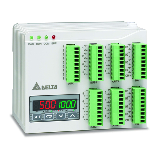
Product Profile & Outline
Panel Layout
Input
The standard DTE main unit is attached with 4 channels of inputs. You can purchase additional DTE20T or DTE20P to expand
the number of input channels. DTE supports maximum 8 channels of inputs which belong to group INA and group INB. Each
group possesses 4 input channels.
DTE series supports the following input sensors:
Input Sensor Type
Register Value
For DTE10P / DTE20P
Temperature measurement resistance (Cu50)
13
Platinum resistance (Pt100)
12
Platinum resistance (JPt100)
11
For DTE10T / DTE20T
Thermocouple TXK type
10
Thermocouple U type
9
Thermocouple L type
8
Thermocouple B type
7
Thermocouple S type
6
Thermocouple R type
5
Thermocouple N type
4
Thermocouple E type
3
Thermocouple T type
2
Thermocouple J type
1
Thermocouple K type
0
Note: The default setting in DTE10T is "thermocouple K type". The default setting in DTE10P is "Pt100".
Communication address: Input sensor types at H10A0 ~ H10A7; input upper limits at H1010 ~ H1017; input lower limits at
H1018 ~ H101F.
Output
DTE supports maximum 16 channels of outputs, belonging to output groups OUT1, OUT2, SUB1 and SUB2, each group with 4
channels. See the explanations below for how input channels correspond to output groups.
Without group INB (4 channels of input): Every channel corresponds to 2 groups of output and 2 groups of alarms. OUT1 and
SUB1 are for control output, and OUT1 can be used for proportional output. OUT2 and SUB2 are fixed for alarm output.
With group INB (8 channels of input): Every channel is paired with 2 groups of outputs. OUT1 and OUT2 are used for control
output or proportional output of CH1 ~ CH8. SUB1 and SUB2 are used for control output or alarm output.
See Table 1 for the relations between input and output.
4 channels of input
Output Group
INA (CH1 ~ CH4)
INA (CH1 ~ CH4)
Main control output or
Main control output or proportional
OUT1
proportional output
output
OUT2
Alarm 1 output
No corresponding output
SUB1
Control output
Control output or alarm output
SUB2
Alarm 2 output
No corresponding output
Table 1
Note: SUB1 and SUB2 do not support DTE20L and DTE20C. Please install the optional output modules you purchase into
the correct slot.
Communication Address of Output & How to Set up Parameters:
See Table 2 for the communication addresses of output and Table 3 for the definition of the value in the address.
OUT1, OUT2
SUB1, SUB2
DTE10T/P
1
I/O terminals
2
Status LED
3
Display and setup unit
OUT1, OUT2**
4
DIN rail clip
SUB1, SUB2**
5
Power input port
6
RS-485 communication port
*
7
Extension module fixing clip
When there are only 4 channels of inputs, SUB1 cannot be used for alarm output but heating/cooling control only.
8
Extension port
**
When there are only 4 channels of inputs, OUT2 and SUB2 cannot be set up by the user but set up automatically as "alarm
output" by the controller.
Control Output:
DTE offers PID control, ON/OFF control, manual control and programmable PID control. Control output methods are set at
address H10B8 ~ H10BF (default = 0: PID), PID parameters at H1028 ~ H105F, ON/OFF parameters at H1058 ~ H106F, and
manual control parameters at H1070 ~ H107F.
Alarm Output:
DTE offers 12 alarm modes. The alarm modes are set up at address H10C0 ~ H10C7, upper limits at H1080 ~ H1087 and
lower limits at H1088 ~ H108F.
SV
0
No alarm
Alarm output is enabled when the temperature reaches upper and lower
1
limits: The alarm will be enabled when PV exceeds SV + AL-H or falls below
SV – AL-L.
Alarm output will be enabled when the temperature reaches the upper limit:
2
The alarm will be enabled when the PV exceeds SV + AL-H.
Alarm output will be enabled when the temperature reaches the lower limit:
3
The alarm will be enabled when the PV falls below SV – AL-L.
Alarm output will be enabled when the PV is between SV + AL-H and SV –
4
AL-L.
Range
Alarm output will be enabled when the temperature reaches the absolute
5
value of the upper and lower limits: The alarm will be enabled when the PV
-50 ~ 150°C
exceeds AL-H or falls below AL-L.
-200 ~ 600°C
Alarm output will be enabled when the temperature reaches the absolute
6
value of the upper limit: The alarm will be enabled when the PV exceeds
-20 ~ 400°C
AL-H.
Alarm output will be enabled when the temperature reaches the absolute
-200 ~ 800°C
7
value of the lower limit: The alarm will be enabled when the PV falls below
-200 ~ 500°C
AL-L.
-200 ~ 850°C
Upper/lower limit standby alarm: The alarm will be enabled when the PV
8
100 ~ 1,800°C
reaches SV and further exceeds SV + AL-H or falls below SV – AL-L.
0 ~ 1,700°C
Upper limit standby alarm: The alarm will be enabled when the PV reaches
0 ~ 1,700°C
9
SV and further exceeds SV + AL-H.
-200 ~ 1,300°C
0 ~ 600°C
Lower limit standby alarm: The alarm will be enabled when the PV reaches
10
SV and further falls below SV – AL-L.
-200 ~ 400°C
-100 ~ 1,200°C
Upper limit hysteresis alarm: The alarm will be enabled when the PV exceeds
-200 ~ 1,300°C
11
SV + AL-H. The alarm will be disabled when the PV falls below SV + AL-L.
Lower limit hysteresis alarm: The alarm will be enabled when the PV falls
12
below SV – AL-H. The alarm will be disabled when the PV exceeds SV –
AL-L.
LED Display
PWR: On
DTE is powered.
RUN: On
Any of the channel is executing.
COM: Flashing
ERR: Indicating errors (red)
ERR LED is on indicates one of the following errors occur, and the output has to be disabled.
1. Memory EEPROM error.
2. Any of the input points is not connected.
8 channels of input
3. Any of the input points exceeds the setup range.
INB (CH5 ~ CH8)
4. Any of the input temperatures has not been stabilized.
No corresponding output
Synchronous Communication Protocol & Auto ID Setup
Main control output or proportional
This function allows the auto setup of communication protocol in extension module DTC2000 and DTC2001 following the
output
communication protocol set in the DTE main unit. The station IDs of DTC decrease. See below for the steps.
No corresponding output
1. Set the auto communication ID of DTE as "1" (communication address: H10F8).
Control output or alarm output
2. Switch off DTE. Connect DTE with extension module DTC2000, DTC2001 and switch on DTE again.
3. Default communication protocol: 9,600bps, 7 bits, Even, 1 stop bit, communication address = 01.
INA
CH1
CH2
CH3
CH4
CH5
CH6
H10A8
H10A9
H10AA
H10AB
H10AC
H10AD
H10B0
H10B1
H10B2
H10B3
H10B4
H10B5
Table 2
Value = 0
Value = 1
Value = 2
Heating control
Cooling control
Proportional output
Heating control
Cooling control
Alarm output*
Table 3
Alarm Mode
Communication in progress
INB
CH7
CH8
H10AE
H10AF
H10B6
H10B7
Value = 3
Disable output
Disable output
Alarm Output Operation
Off
ON
OFF
AL-L
SV
AL-H
ON
OFF
SV
AL-H
ON
OFF
AL-L
SV
ON
OFF
AL-L
SV
AL-H
ON
OFF
AL-L
AL-H
ON
OFF
AL-H
ON
OFF
AL-L
ON
OFF
AL-L
SV
AL-H
ON
OFF
SV
AL-H
ON
OFF
AL-L
SV
ON
OFF
AL-L
AL-H
ON
OFF
AL-H
AL-L
Advertisement

Related Manuals for Delta Electronics Temperature Controller DTE


Summary of Contents for Delta Electronics Temperature Controller DTE
- Page 1 1. Set the auto communication ID of DTE as “1” (communication address: H10F8). 2. Switch off DTE. Connect DTE with extension module DTC2000, DTC2001 and switch on DTE again. 3. Default communication protocol: 9,600bps, 7 bits, Even, 1 stop bit, communication address = 01.
- Page 2 4. This function will consume 3 ~ 5 seconds more when you switch on DTE. RS-485 Communication 1. DTE supports baud rates 2,400/4,800/9,600/19,200/38,400/57,600/115,200 bps and does not support communication format 7, N, 1/8, E, 2/8, O, 2. Communication protocol = Modbus ASCII or RTU.