Table of Contents
Advertisement
Quick Links
Advertisement
Table of Contents

Related Manuals for Delta Electronics CANopen Communication Module DVPCOPM-SL


Summary of Contents for Delta Electronics CANopen Communication Module DVPCOPM-SL
- Page 1 DVPCOPM-SL CANopen Communication Module Application Manual...
-
Page 3: Table Of Contents
Data Mapping in CANopen Network ...10 How to Configure Network by Delta CANopenBuilder Software ... 11 Saving the Configuration Data ...19 CANopen Network Control ...19 DVP-PLC Application Manual CANopen Communication Module DVPCOPM-SL is correctly grounded in order to prevent electromagnetic interference. - Page 4 CANopen Communication Module DVPCOPM-SL SENDING SDO, NMT AND READING EMERGENCY BY LADDER DIAGRAM ... 20 The Principle... 20 Structure of SDO Request Message... 20 Structure of NMT Service Message ... 21 Structure of Emergency Request Message ... 22 Application Examples ... 23 LED INDICATOR &...
-
Page 5: Introduction
Able to indicate Emergency messages in slave from digital display. Able to read Emergency message through the ladder diagram in PLC. SYNC producer; Range: 0 ~ 65,535ms. DVP-PLC Application Manual CANopen Communication Module DVPCOPM-SL Data type BOOL SINT USINT BYTE... -
Page 6: Functions
CANopen Communication Module DVPCOPM-SL As the interface between Delta CANopenBuilder software and CANopen network. The software can configure the network directly through DVPCOPM-SL. In the auto data exchange with DVP-SV, the user only has to program the D register mapped in DVP-SV without applygin FROM/TO instructions. -
Page 7: Product Profile & Outline
1. Model name 2. Extension port DVP-PLC Application Manual CANopen Communication Module DVPCOPM-SL 0ºC ~ 55ºC (temperature); 50 ~ 95% (humidity); pollution degree 2 -25ºC ~ 70ºC (temperature); 5 ~ 95% (humidity) International standard: IEC 61131-2, IEC 68-2-6 (TEST Fc)/IEC 61131-2 & IEC... -
Page 8: Canopen Connection Port
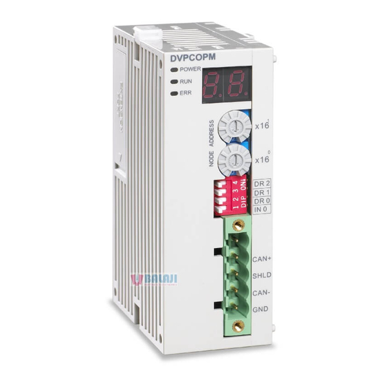
CANopen Communication Module DVPCOPM-SL 3. POWER, RUN, ERR indicators 4. DIN rail clip 5. Digital display CANopen Connection Port The connector is used on the connection to CANopen network. Wire by using the connector enclosed with DVPCOPM-SL. Address Switch The switch is used on setting up the node address of DVPCOPM-SL on CANopen network. Range: 1 ~ 7F (0, 88 ~ FF are forbidden). -
Page 9: Digital Indicator
Open the DIN rail clip on DVP-SV and DVPCOPM-SL. Insert DVP-SV and DVPCOPM-SL onto the DIN rail. Clip up the DIN rail clips on DVP-SV and DVPCOPM-SL to fix DVP-SV and DVPCOPM-SL on the DIN rail, as shown below. DVP-PLC Application Manual CANopen Communication Module DVPCOPM-SL DVPCOPM DVP28SV POWE R D R 2... -
Page 10: Connecting To Canopen Connection Port
CANopen Communication Module DVPCOPM-SL Connecting to CANopen Connection Port Please wire following the PIN definition of the connection port. There are two communication interfaces on DVP-SV to communicate with the PC. COM1 is the standard RS-232 interface, and COM2 RS-485. Both interfaces comply with Modbus protocol. The PC communicates directly to PLC through COM1. - Page 11 P3-00 P3-01 P3-02 P3-06 Constructing the CANopen network following the figure below. ASD-B DVP-PLC Application Manual CANopen Communication Module DVPCOPM-SL CANopen configuration software for DVPCOM-SL master Node address 02 (connected to ASD-B) 03 (connected to DVP-12SA) Set value 100 (rpm)
-
Page 12: Data Mapping In Canopen Network
CANopen Communication Module DVPCOPM-SL About the connection between IFD9503 and PLC, IFD9503 and ASD-B, or IFD9503 and other equipment, please refer to Chapter 13. For the electrical specifications of ASD-B, please refer to ASD-B user manual. Data Mapping in CANopen Network... -
Page 13: How To Configure Network By Delta Canopenbuilder Software
(3) Set up the communication parameters in the PC and DVP-SV, e.g. the communication port, address, baud rate and communication format. Item COM Port DVP-PLC Application Manual CANopen Communication Module DVPCOPM-SL 15 14 13 12 11 10 9 Multi-function digital output Multi-function digital input Function... - Page 14 CANopen Communication Module DVPCOPM-SL Item Address Baud rate Data Bits Parity Stop Bit Mode Click on “OK” and return to the main page. (4) Select “Network” => ”Online”, and the “Select Communication Channel” dialog box will appear. In this example, if the connection with DVP-SV is in normal status, you will see the screen as below.
- Page 15 CANopen Communication Module DVPCOPM-SL (6) In normal condition, after the scan is over, you will find the master and all the slaves displayed in CANopen network, as below. Setting up parameters in CANopen master Select “Network” => ”Master Parameter”, and you will see the dialog box as below.
- Page 16 CANopen Communication Module DVPCOPM-SL Work Mode: The work mode of DVPCOPM-SL. You can select either “Master Mode” or “Slave Mode”. Cycle Period: The period of sending synchronous information. Master’s heartbeat time: Time for DVPCOPM-SL to send out heartbeat. After all the parameters are set up, click on “OK".
- Page 17 Auto SDO cannot be longer than 8 bytes, and every slave is able to posses maximum 20 auto SDOs. PDO mapping: In the “Node Configuration…” page, select a TxPDO or RxPDO in “Configured DVP-PLC Application Manual CANopen Communication Module DVPCOPM-SL...
- Page 18 CANopen Communication Module DVPCOPM-SL PDO” and click on “PDO Mapping”, and you will enter the “PDO Mapping…” page as below. You can add the parameters in “Available Objects from EDS file” into “Mapped Objects”. The total length of the parameters added in each PDO cannot exceed 8 bytes. After the configuration is completed, click on “OK”.
- Page 19 D registers in DVP-SV from the Output Table and Input Table below. (3) Add also Node 002 into the node list, and you will be able to see how the I/O data correspond to D DVP-PLC Application Manual CANopen Communication Module DVPCOPM-SL > to add this node into...
- Page 20 CANopen Communication Module DVPCOPM-SL registers in DVP-SV from the Output Table and Input Table below. Click on “OK” to complete setting up the node list. Downloading the data to the master Select “Network“ => “Download” to download the configuration data to DVPCOPM-SL master. If the PLC is in RUN status at this moment, you will be given a warning saying that you have to stop the operation before the download.
-
Page 21: Saving The Configuration Data
(Multi-Function Digital Output, mapped on D6036 of DVP-SV) to D0 in DVP-SA (mapped on D6282 of DVP-SV). The program in DVP-SA MPU (slave): M1002 DVP-PLC Application Manual CANopen Communication Module DVPCOPM-SL D6032 D6286 D6286 D6036... -
Page 22: Sending Sdo, Nmt And Reading Emergency By Ladder Diagram
CANopen Communication Module DVPCOPM-SL Program explanations: 1. The first 3 rows of the program set up the communication format between DVP-SA and IFD9503, which is 115,200bps, 7E1-ASCII; communication port is COM2. 2. When M0 = On, send the input status of X20 ~ X28 on DVP-08ST to D256, and send the data in b0 ~ b15 of D0 to M10 ~ M25. -
Page 23: Structure Of Nmt Service Message
Structure of NMT Service Message You can send the NMT request message to D6250 ~ D6281, and the slave will not respond with a message. DVP-PLC Application Manual CANopen Communication Module DVPCOPM-SL Editing area Request Message 15 14 13 12 11 10 9... -
Page 24: Structure Of Emergency Request Message
CANopen Communication Module DVPCOPM-SL PLC device D6250 D6251 Message Header D6252 D6253 D6254 Command: Fixed to “01Hex”. ReqID: The request ID. Whenever an NMT request message is sent out, the message will be given a ReqID for the CANopen master to identify. For the next NMT request message to be sent out, you have to change the ID number. -
Page 25: Application Examples
IFD9503. DVPCOPM C A N+ S H LD C A N- G N D Node 1 DVP-PLC Application Manual CANopen Communication Module DVPCOPM-SL Response Message 15 14 13 12 11 10 9 DVP28SV STOP Master CANopen Node 2... - Page 26 CANopen Communication Module DVPCOPM-SL Required settings in DVPCOPM-SL: Parameter Node address Baud rate Required settings in IFD9503: Parameter Node address Baud rate Required settings in VFD-B AC motor drive: Parameter 02-00 02-01 09-00 09-01 09-04 Devices in PLC: PLC device...
- Page 27 When M0 = On, set the content in index 2047, sub index 2 (i.e. the control word of the target temperature) in IFD9503 to 0104Hex (i.e. 26.0°C). Please note that you have to write 0401Hex into D6255 of the PLC. Node 1 DVP-PLC Application Manual CANopen Communication Module DVPCOPM-SL H0101 D6250 H0004 D6251...
- Page 28 CANopen Communication Module DVPCOPM-SL Required settings in DVPCOPM-SL: Parameter Node address Baud rate Required settings in IFD9503: Parameter Node address Baud rate Required settings in DTA temperature controller: Parameter Devices in PLC PLC device SDO request message editing area SDO response...
-
Page 29: Led Indicator & Trouble-Shooting
DVPCOPM-SL is normal. RUN LED and ERR LED display the current operational status. The digital display shows the node address of DVPCOPM-SL and error messages from the slave. DVP-PLC Application Manual CANopen Communication Module DVPCOPM-SL ZRST D6000 D6031... -
Page 30: Power Led
CANopen Communication Module DVPCOPM-SL POWER LED LED status Power is abnormal. Green light On Power is normal. RUN LED LED status No power Green light single DVPCOPM-SL in STOP status flash Green light DVPCOPM-SL in pre-operational blinking status Green light steady... - Page 31 The sending buffer in DVPCOPM-SL is full. The receiving buffer in DVPCOPM-SL is full. DVP-PLC Application Manual CANopen Communication Module DVPCOPM-SL Indication Check and make sure the power of DVPCOPM-SL works normally. Re-power DVPCOPM-SL. Make sure the bus works normally and re-power DVPCOPM-SL.
- Page 32 CANopen Communication Module DVPCOPM-SL MEMO DVP-PLC Application Manual...