Table of Contents
Advertisement
Quick Links
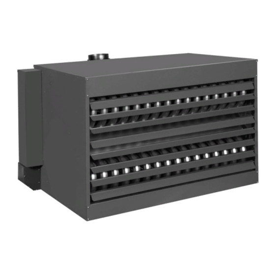
Installation, Operation and Maintenance
Separated Combustion Tubular
Gas Fired Blower Style Unit Heater
Model:
GKNE
Only qualified personnel should install and service the equipment. The installation, starting up, and servicing of
heating, ventilating, and air-conditioning equipment can be hazardous and requires specific knowledge and training.
Improperly installed, adjusted or altered equipment by an unqualified person could result in death or serious injury.
When working on the equipment, observe all precautions in the literature and on the tags, stickers, and labels that are
attached to the equipment.
August 2020
SAFETY WARNING
GKNE-SVX001B-EN
J30-09411
Advertisement
Table of Contents

Related Manuals for Trane GKNE


Summary of Contents for Trane GKNE
- Page 1 Installation, Operation and Maintenance Separated Combustion Tubular Gas Fired Blower Style Unit Heater Model: GKNE J30-09411 SAFETY WARNING Only qualified personnel should install and service the equipment. The installation, starting up, and servicing of heating, ventilating, and air-conditioning equipment can be hazardous and requires specific knowledge and training.
- Page 2 PRIOR to Practices servicing the unit. NEVER PERFORM ANY Trane believes that responsible refrigerant practices are SWITCHING, DISCONNECTING, OR VOLTAGE TESTING WITHOUT PROPER ELECTRICAL PPE AND important to the environment, our customers, and the air conditioning industry.
- Page 3 Copyright This document and the information in it are the property of Trane, and may not be used or reproduced in whole or in part without written permission. Trane reserves the right to revise this publication at any time, and to make changes to its content without obligation to notify any person of such revision or change.
-
Page 4: Table Of Contents
....38 Equipment Start-Up ..... 40 GKNE-SVX001B-EN... -
Page 5: Description
1. Open windows. combustion, which can cause death or serious illness. 2. Don't touch electrical switches. The state of California has determined that these substances may cause cancer, birth defects, or other 3. Extinguish any open flame. reproductive harm. GKNE-SVX001B-EN... -
Page 6: Model Number Description
Two-Stage, Direct Spark Ignition Electronic Modulating w/Duct Sensing & Room Override Stat Digit 10 — Design Sequence First Design Digit 11 — Heat Exchanger Material Standard (Aluminized Steel) 409 Stainless Steel Digit 12, 13, 14 — Reserved for Future Use Not Used GKNE-SVX001B-EN... -
Page 7: General Safety Information
All precautions must be taken to perform requirements of the unit heater, or damage to the unit this operation in a safe manner! will result! Follow installation instructions CAREFULLY to avoid creating unsafe conditions. All wiring should be done and GKNE-SVX001B-EN... - Page 8 "H" Depth to Centerline Flue (121) (130) 25-1/4 37-1/4 55-1/4 "M" Overall Unit Width (641) (946) (1403) 49-3/4 49-3/8 56-1/8 53-3/8 56-1/8 "P" Overall Unit Depth (1264) (1254) (1426) (1356) (1426) Flue Size Diameter - in (mm) (127) (152) GKNE-SVX001B-EN...
- Page 9 (610 to 1372m), the unit must be field derated to 90% of the normal altitude rating, and be so marked in accordance with the ETL certification. See Table 10 for field deration information. (b) LEGEND: SPH = SPLIT PHASE, CAP. START = CAPACITOR START (c) Flue collar is factory supplied with unit; to be field installed per included instructions. GKNE-SVX001B-EN...
-
Page 10: Installation
8 feet (2.4m) above the floor in shops, offices calculations where the unit heater output equals or and other sections of the hangar where aircraft are not exceeds heat loss. stored or housed. Refer to current ANSI/NFPA No. 409, Aircraft Hangars. In Canada, installation is suitable in GKNE-SVX001B-EN... - Page 11 (19.8) (21.3) (22.9) (24.1) (25.3) (29.0) (33.2) (35.1) (36.6) 60° (3.7) (18.3) (19.5) (20.7) (21.9) (23.2) (25.6) (30.5) (31.4) (32.9) (4.6) (15.2) (16.5) (17.1) (18.6) (19.8) (21.6) (25.9) (26.8) (28.7) (6.1) (14.9) (15.8) (16.8) (18.0) (19.8) (23.5) (24.7) (25.9) GKNE-SVX001B-EN...
- Page 12 Failure to heed this warning may result in property damage or personal injury! GKNE-SVX001B-EN...
-
Page 13: Gas Piping
These valves may not be completely shut off, exposing the gas valve to excessive pressure and damage. Pipe Sizing To provide adequate gas pressure to the gas unit heater, size the gas piping as follows: GKNE-SVX001B-EN... -
Page 14: Pipe Installation
5. Standard Unit Heaters, optional two-stage units are Use pipe joint sealant resistant to the action of supplied with a combination valve which includes: liquefied petroleum gases regardless of gas conducted. a. Manual "A" valve b. Manual "B" valve c. Solenoid valve GKNE-SVX001B-EN... - Page 15 (0.9 kPa) (2.5 kPa) 14.0 inch WC Max. 14.0 inch WC Max. (3.5 kPa) (3.5 kPa) Supply Inlet Pressure 5.0 inch WC Min. 11.0 inch WC Min. (1.2 kPa) (2.7 kPa) (a) For single stage application only at normal altitudes. GKNE-SVX001B-EN...
-
Page 16: Blower Set Up And Adjustment
2 BEARINGS. FOR 300/400 UNITS THE BLOWER ASSEMBLY CONSISTS OF 2 WHEELS, 2 HOUSINGS, 1 SHAFT AND 3 BEARINGS. CAUTION Never operate the unit beyond the specified limits or severe damage to, and or premature failure of, the unit will result! GKNE-SVX001B-EN... -
Page 17: Motor And Pulley
AL74 7.0 AL84 8.0 AL104 10.0 Turns Open 4-1/2 3-1/2 2-1/2 1-1/2 1027 4-1/2 1064 1101 3-1/2 1137 1028 1174 1061 2-1/2 1211 1094 1247 1127 1-1/2 1284 1161 1006 1321 1194 1035 1357 1227 1064 1394 1260 1093 GKNE-SVX001B-EN... -
Page 18: Electrical Connections
Should any high limit wires have to be replaced, they 3. Dead Areas - Areas where the air cannot circulate must be replaced with wiring material having a freely, such as behind doors or in corners. temperature rating of 200°C minimum. GKNE-SVX001B-EN... - Page 19 Electrical Connections Figure 10. Separated combustion tubular blower units 100-150 with single stage ignition, natural gas and propane (LP) gas GKNE-SVX001B-EN...
- Page 20 Electrical Connections Figure 11. Separated combustion tubular blower units 100-150 with two stage ignition, natural gas and propane (LP) GKNE-SVX001B-EN...
- Page 21 Electrical Connections Figure 12. Separated combustion tubular blower units 175-400 with single stage ignition, natural gas and propane (LP) gas GKNE-SVX001B-EN...
- Page 22 Electrical Connections Figure 13. Separated combustion tubular blower units 175-400 with two stage ignition, natural gas and propane (LP) GKNE-SVX001B-EN...
-
Page 23: Venting
Failure to open such a damper prior to operating gas unit will result in the spillage of flue gas into the occupied space. Vertically Vented Unit Heaters (Category I) Observe the following precautions when venting the unit: GKNE-SVX001B-EN... -
Page 24: Horizontally Vented Unit Heaters (Category Iii)
1 foot 1 foot (0.3m) (a) Above maximum anticipated snow depth. NOTICE Combustion and exhaust venting instructions below describe two-pipe venting. If venting concentrically, a Combustion Air Inlet Kit is required and instructions included in the kit should be followed. GKNE-SVX001B-EN... -
Page 25: Combustion Air Venting And Piping
To do so may result in pipes downward 1/4-inch. per foot (21mm/m) toward serious damage to the unit and or severe personal the inlet cap to facilitate drainage. Vertical combustion injury or death! air pipes should be piped as depicted in Figure GKNE-SVX001B-EN... - Page 26 1). The opening must be insulated and flashed in accordance with applicable installation codes. See Figure A HORIZONTAL section of an exhaust vent system that passes through a combustible wall must be constructed and insulated as shown in Figure Figure GKNE-SVX001B-EN...
- Page 27 Venting Figure 15. Vertical arrangement - Single wall vent system to single wall termination CAT-3619C Figure 16. Horizontal intake/Vent locations CAT-2765C Figure 17. Horizontal arrangement - Single wall vent system to single wall termination CAT-3620F GKNE-SVX001B-EN...
- Page 28 1. Installation must conform with local building codes, or in the absence of local codes, with current CSA B149.1, Installation Codes for Natural Gas Burning Appliances and Equipment, or CSA B149.2, Installation Codes for Propane Gas Burning Appliances and Equipment. GKNE-SVX001B-EN...
-
Page 29: Operation
The thermostat must be mounted on a vertical, vibration-free surface free from air currents and in accordance with the furnished instructions (also refer to Electrical Section). GKNE-SVX001B-EN... -
Page 30: Gas Input Rate
Once the proper adjustments are follow steps "a" through "d" above. If the unit is not so made in the field, attach label #J17-06459 to the unit, and GKNE-SVX001B-EN... - Page 31 1 Clogged main burners. 2. Replace manifold assembly. 2. Misaligned orifices. 3. Refer to "Installation - Clearances" and 3. Insufficient combustion air. "Venting" to ensure unit is properly mounted and vented. 4. Possibly over fired. 4. Check gas input and manifold pressures. GKNE-SVX001B-EN...
- Page 32 Refer to "Electrical Connections." 2. Excessive thermostat heat anticipator 3. Check for proper air supply across heat setting. exchanger and proper gas supply. 3. Unit cycling on high limit. 4. Relocate thermostat away from outside wall or 4. Thermostat located improperly. drafts. GKNE-SVX001B-EN...
- Page 33 Q. Cold air is delivered during heater operation. 1. Incorrect manifold pressure or input. 1. Test and reset manifold pressure (see Table 4 - "Gas Piping Requirements"). 2. Air throughput too high. 2. Check Blower and Motor pulleys. Replace or tighten as necessary. GKNE-SVX001B-EN...
- Page 34 Table 13. Separated combustion tubular blower troubleshooting with LED indicator assistance LED STATUS INDICATES CHECK/REPAIR Slow Flash Control OK, no call for heat. Not Applicable Fast Flash Control OK, call for heat present. Not Applicable GKNE-SVX001B-EN...
- Page 35 Limit or rollout switch is open. 3. Incorrect airflow due to blockage or motor not operating. 5. Flashes Flame sensed while gas valve is off. Flame probe miswired or shortened. 6. Flashes On-board microprocessors disagree. Thermostat is interfering with control board. GKNE-SVX001B-EN...
-
Page 36: Maintenance
3. To clean or replace the burners, remove burner cover. Remove top strip from above burners. Lift burners up and pull away from manifold to remove. 4. With the burners removed, wire brush the inside surfaces of the heat exchanger. GKNE-SVX001B-EN... -
Page 37: Limited Warranty
5. THIS LIMITED WARRANTY IS IN LIEU OF ALL WARRANTIES, EITHER EXPRESS OR IMPLIED, AND ALL SUCH OTHER WARRANTIES, INCLUDING WITHOUT LIMITATION IMPLIED WARRANTIES OF MERCHANTABILITY OR FITNESS FOR A PARTICULAR PURPOSE, ARE HEREBY DISCLAIMED AND EXCLUDED FROM THIS LIMITED WARRANTY. IN NO GKNE-SVX001B-EN... -
Page 38: Identification Of Parts Separated Combustion Blower Unit Heaters
Assembly Connection Motor Belt Guard Blower Transformer Fan Motor Connection Electrical Control Flame Sensor Panel Assembly Manifold Burner Assembly Bracket Assembly Control Board Ignitor Base Burner Cover Panel Hinge Terminal Block D9049 Sight Glass D9064 Electrical Control Panel Door GKNE-SVX001B-EN... - Page 39 D4780 How To Order Replacement Parts Please send the following information to your local representative: if further assistance is needed, contact the manufacturer's customer service department. • Unit Number • Serial Number • Part Description and Number as shown GKNE-SVX001B-EN...
-
Page 40: Equipment Start-Up
Check rotation of main blower(s). External static pressure _________ in. W.C. Check motor amps. L1_____ L2_____ L3_____ Cycle by thermostat or operating control. Combustion readings: Carbon Monoxide:______ PPM Carbon Dioxide:________% Remarks:_____________________________________________________________________________________________ ________________________________________________________________________________________________________________ ________________________________________________________________________________________________________________ ________________________________________________________________________________________________________________ GKNE-SVX001B-EN... - Page 44 For more information, please visit trane.com or tranetechnologies.com. Trane has a policy of continuous product and product data improvement and reserves the right to change design and specifications without notice. We are committed to using environmentally conscious print practices.