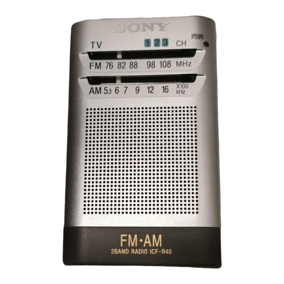
Summary of Contents for Sony ICF-R40
- Page 1 ICF-R40 SERVICE MANUAL Tourist Model Ver 1.0 1999. 03 SPECIFICATIONS FM/AM RADIO MICROFILM...
-
Page 2: Section 1 General
SECTION 1 GENERAL HOW TO CHANGED THE CERAMIC FILTERS This section is extracted from This model is used two ceramic filters of CF2 and CF3. instruction manual. You must used same type of color marked ceramic filters in order to meet same specifications. Therefore, the ceramic filter must changed two pieces together since it’s supply two pieces in one package as a spare parts. -
Page 3: Section 2 Disassembly
SECTION 2 DISASSEMBLY Note: Follow the disassembly procedure in the numerical order given. CABINET (REAR) 2 Open the “lid, battery case” in the direction of arrows A to B . 1 Pull out the ear receiver. 3 two screws (DIA. 1.4 × 4) 9 claw !¡... - Page 4 REEL ASSY 2 three screws (B1.4 × 3) 4 reel assy 1 blind plate 3 Draw the ear receiver in the direction of the arrow. – 4 –...
-
Page 5: Section 3 Dial Pointer Setting
SECTION 3 DIAL POINTER SETTING Note: Follow the assembly procedure in the numerical order given. 4 knob (tune) 1 Insert the pointer in the groove of cabinet (front) assy and slide in the direction of the arrow A . 3 gear (midway) pointer 2 Set the tip of pointer to the marking... -
Page 6: Section 4 Electrical Adjustments
SECTION 4 ELECTRICAL ADJUSTMENTS FM FREQUENCY COVERAGE ADJUSTMENT 0 dB=1 µV Adjust for a maximum reading on level meter. [FM] 75 MHz Setting: CT1-3 109.5 MHz POWER switch: AUTO OFF Band switch: FM FM TRACKING ADJUSTMENT Output select switch: @ (earphone) Adjust for a maximum reading on level meter. - Page 7 ICF-R40 SECTION 5 DIAGRAMS 5-1. BLOCK DIAGRAM • SIGNAL PATH : FM : AM CT1-4, L2 FM TRACKING FM RF (EARPHONE) CT1-4 FM/AM FRONT-END, CV1-4 FM/AM IF AMP, DET, AGC, AF AMP (EARPHONE) TUNE FM RF 10.7MHz BAND-PASS FM IF...
-
Page 8: Printed Wiring Board
ICF-R40 5-2. PRINTED WIRING BOARD • Semiconductor Note on Printed Wiring Board: • X : parts extracted from the component side. Location • Y : parts extracted from the conductor side. Ref. No. Location W : indicates side identified with part number. -
Page 9: Schematic Diagram
ICF-R40 5-3. SCHEMATIC DIAGRAM • IC Block Diagrams IC1 CXA1280N 30 29 28 27 26 21 20 18 17 16 AF POWER AM IF AMP, DET, AGC TUNING FM IF METER FRONT-END DISCRIMINATOR FRONT-END 8 9 10 12 13 14 15... -
Page 10: Section 6 Exploded View
SECTION 7 SECTION 6 MAIN EXPLODED VIEW ELECTRICAL PARTS LIST NOTE: NOTE: • -XX and -X mean standardized parts, so they • Items marked “*” are not stocked since they • Due to standardization, replacements in the • Items marked “*” are not stocked since they When indicating parts by reference number, please include the board. -
Page 11: Accessories And Packing Materials
MAIN Ref. No. Part No. Description Remark Ref. No. Part No. Description Remark 1-216-805-11 METAL CHIP 1/16W 1-216-833-11 METAL CHIP 1/16W 1-216-825-11 METAL CHIP 2.2K 1/16W 1-216-839-11 METAL CHIP 1/16W 1-216-837-11 METAL CHIP 1/16W 1-216-845-11 METAL CHIP 100K 1/16W 1-216-829-11 METAL CHIP 4.7K 1/16W 1-216-829-11 METAL CHIP... - Page 12 ICF-R40 Sony Corporation 99C05031-1 Printed in Japan © 1999. 3 9-926-942-11 Parsonal A&V Products Company Published by Quality Engineering Dept. – 16 – (Shinagawa)


