Viessmann Vitocrossal Installation Instructions Manual
Hide thumbs
Also See for Vitocrossal:
- Service instructions manual (112 pages) ,
- Installation instructions manual (44 pages) ,
- Installation instructions for contractors (40 pages)

Related Manuals for Viessmann Vitocrossal


Summary of Contents for Viessmann Vitocrossal
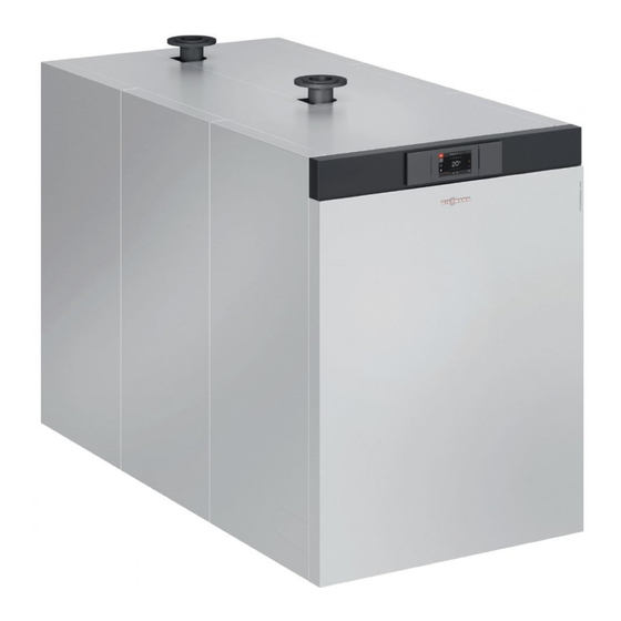
- Page 1 VIESMANN Installation instructions for contractors Vitocrossal Type CRU, 800 to 1000 kW Gas condensing boiler VITOCROSSAL Dispose after installation. 6151133 GB 1/2020...
- Page 2 Safety instructions Please follow these safety instruc- tions closely to prevent accidents and material losses. Safety instructions explained Danger Note This symbol warns against the risk Details identified by the word "Note" of injury. contain additional information. Please note This symbol warns against the risk of material losses and environmen- tal pollution.
- Page 3 Repair work Please note Repairing components that fulfil a safety function can compromise the safe operation of the system. Replace faulty components only with genuine Viessmann spare parts.
-
Page 4: Table Of Contents
Index Information Disposal of packaging ................Symbols ....................Intended use ..................Product information ................Burner ....................■ System examples ................■ Preparing for installation Clearances and dimensions ..............Anti-vibration boiler supports .............. ■ Thermal insulation components ............. Thermal insulation, pack 1 ..............■... -
Page 5: Disposal Of Packaging
Disposal of packaging Please dispose of packaging waste in line with statu- tory regulations. Symbols Symbol Meaning Reference to other document containing further information Step in a diagram: The numbers correspond to the order in which the steps are carried out. Warning of material losses and environ- mental pollution Live electrical area... -
Page 6: Product Information
E and natural gas LL ■ Permissible operating pressure for the heating sys- tem: 6 bar/0.6 MPa. Burner Information for the installation of the burner "MatriX-Disk burner" installation instructions System examples Available system examples: See www.viessmann- schemes.com. -
Page 7: Clearances And Dimensions
Clearances and dimensions Note Vertical flue gas pipework The stated clearances are recommended clearances. (300) Minimum clearances are indicated in brackets. (300) Fig. 2 Note If routing the flue gas vertically, allow space for work- ing on the control unit. (100) Fig. -
Page 8: Anti-Vibration Boiler Supports
Clearances and dimensions (cont.) Anti-vibration boiler supports Fig. 3 Permissible load 2970 Boiler front Length ■ Quantity ■ Boiler back Length ■ Quantity ■ Boiler front ■ Boiler back ■ Spring elements, unloa- ■ Spring elements, loa- 38-39 ■ Thermal insulation components The thermal insulation and casing are supplied in two packs. -
Page 9: Thermal Insulation, Pack 1
Control unit cover 0019 Side panel, front left 0036 Back panel, centre 0027 Front panel 0037 Back panel, bottom 0028 Control unit panel 0038 Viessmann logo 0029 Top panel, front 0039 Vitocrossal logo 0030 Top panel, left 0031 Top panel, right... -
Page 10: Thermal Insulation, Pack 2
Thermal insulation components (cont.) Thermal insulation, pack 2 0011 0009 0013 0014 0013 0013 0012 0008 0013 0007 0010 0006 0005 0008 0041 0021 0020 0007 0022 0006 0005 0041 0017 0015 0025 0026 0002 0024 0001 0023 0040 0016 0018 Fig. - Page 11 Thermal insulation components (cont.) Pos. Part Pos. Part 0024 Centre side panel 1, right 0040 Fixings: Spring hooks, edge protection, vari- ous screws and washers, ball studs, links/ 0025 Centre side panel 2, right joints and gas springs 0026 Side panel, back right 0041 Support plate...
-
Page 12: Siting The Combustion Chamber Module
Siting the combustion chamber module Installation without anti-vibration boiler supports 1. Position a plate, e.g. a flat steel strip, underneath the adjusting screws to distribute the load evenly. Fig. 6 Installation with anti-vibration boiler supports To ensure that the spring elements are uniformly loa- 4. -
Page 13: Attaching The Heat Exchanger Module To The Combustion Chamber Module
Attaching the heat exchanger module to the combustion chamber module Please note 1. Lift the heat exchanger module by the lifting eyes. Scratches inside the combustion chamber or on components that come into contact with flue gas can lead to corrosion damage. Never place tools or other objects inside the combustion chamber. -
Page 14: Fitting The Foot Supports To The Heat Exchanger Module
Attaching the heat exchanger module to the… (cont.) Fitting the foot supports to the heat exchanger module Note Foot supports are included with the heat exchanger module. Fig. 8... -
Page 15: Levelling The Combustion Chamber And Heat Exchanger Module Horizontally
Levelling the combustion chamber and heat exchanger module horizontally Fig. 9 Connections on the heating water side Note The boiler is only suitable for fully pumped hot water heating systems. - Page 16 Connections on the heating water side (cont.) Fig. 10 Female connection for control equipment: R ½ Boiler flow: PN 6, DN 100 with sensor well for boiler water temperature sensor Female connection for pressure limiter: R ½ Safety connection (safety valve): R 2 Boiler return 2: PN 6, DN 100 Boiler return 1: PN 6, DN 100 Drain outlet: R 1...
-
Page 17: Fitting The Thermal Insulation
Only fill the boiler with water that complies Please note with the "Water quality requirements": See Mechanically loaded hydraulic connections "Vitocrossal, type CRU" service instructions lead to leaks, vibrations and appliance dam- age. 5. Thermally insulate the hydraulic lines. Connect on-site lines so that they are free of load and torque stress. -
Page 18: Mounting The Burner
Mounting the burner "MatriX-Disk burner" installation instructions Attach rails, top and bottom M 6 x 10 Fig. 12 Rail, top (long) Rail, bottom (short) Rail, top (short) Support plate Rail, bottom (long) -
Page 19: Lay Electrical Cables On The Rails
Lay electrical cables on the rails Fig. 13 Cables 230 V~/400 V~ Boiler water temperature sensor Extra low voltage (ELV) leads Cables with plugs for connection to Vitotronic con- Cables with plugs for the burner and programming trol unit unit Please note Please note Damage to the connecting cables and sensor... -
Page 20: Fit The Tie-Bars
Fit the tie-bars Ø 4.8 Ø 3.5 Ø 4.8 Fig. 14 Burner electrical connection "MatriX-Disk burner" installation instructions... -
Page 21: Fitting The Side Panels
Fitting the side panels Ø 4.8 Ø 4.8 Fig. 15... -
Page 22: Fitting The Control Unit To The Top Back Panel
Fitting the control unit to the top back panel Note Edge protectors are supplied in pack 2 of the ther- mal insulation. Fig. 16... -
Page 23: Fitting The Back Panels
Fitting the back panels Ø 3.5 Fig. 17 Plug for the flue gas dampers Flue gas temperature sensor LAN socket... -
Page 24: Connecting The Control Unit
Connecting the control unit 400 V~ Fig. 18 Power supply for the control unit Power cable 400 V~ to the external power supply Danger Please note Incorrect wiring can lead to serious injury from Damage to the cables/leads causes malfunction. electrical current and result in appliance dam- The cables/leads must not come into contact age. -
Page 25: Inserting Cables And Applying Strain Relief
Connecting the control unit (cont.) Inserting cables and applying strain relief 8. 8. 1. Fig. 19 Cables with moulded strain relief On-site cables; strip up to 100 mm insulation. On-site connection to the Vitotronic control unit Installation and service instructions for the Vitotronic control unit... -
Page 26: Overview Of Burner Control Unit Connections
Connecting the control unit (cont.) Overview of burner control unit connections Fig. 20 Junction box Fuel valve BV2 Mains connection to main MCB/fuse 400 V/50 Hz, Display and programming unit see the following chapter Gas pressure switch GDW2 Burner control unit VUC 310 Air pressure switch 1 Flame monitor (ionisation current) Gas pressure switch GDW1... -
Page 27: Power Supply
Connecting the control unit (cont.) Power supply Danger Danger Incorrectly executed electrical installations can Incorrect core assignment can result in serious result in injuries from electrical current and dam- injury and damage to the appliance. age to the appliance. Never interchange cores "L" and "N". Connect the power supply and implement all Danger safety measures (e.g. - Page 28 Connecting the control unit (cont.) Overview of electrical connections for the mains connection box 400 V/50 Hz L2 L3 PE PE PE L1 L1 L2 L3 4 N N N 1L1 3L2 5L3 2T1 4T2 6T3 400V~ 100A 100A Base I Fig.
-
Page 29: Fitting The Top Panels And Control Unit Cover
Fitting the top panels and control unit cover Ø 4,8 Ø 4,8 Ø 4,8 Ø 4,8 M 5 x 16 Fig. 22 Danger The absence of system component earthing can lead to serious injury from electric current if an electrical fault occurs. The appliance and the pipework must be con- nected to the equipotential bonding of the build- ing. -
Page 30: Fitting The Front Top Panel For The Control Unit
Fitting the front top panel for the control unit Ø 4.8 Fig. 23 Fitting the top front panel Note Links , ball studs and gas springs are sup- plied in pack 2 of the thermal insulation. - Page 31 Fitting the top front panel (cont.) M 6 x 20 Fig. 24...
-
Page 32: Connecting The Programming Unit
Connecting the programming unit Fig. 25 LAN cable Data cable to the control unit Power supply for programming unit (230 V~) -
Page 33: Fitting The Trap
Fitting the trap Fig. 26 Danger If the trap is not full, flue gas can escape. Escaping flue gas can cause life threatening carbon monoxide poisoning. Always fill the trap with water before commis- sioning. Connecting the neutralising system Neutralising system installation instructions 1. -
Page 34: Connections On The Flue Gas Side
Connections on the flue gas side It is essential that a boiler flue connection (accesso- ries) is used for connecting the flue outlet. 1. Fit the boiler flue connection as shown in the dia- gram. 2. Route the flue pipe with the shortest possible run, maintaining a slight rise to the chimney. -
Page 35: Fitting The Front Side Panels
Fitting the front side panels M6 x 10 Fig. 29 Connections on the gas side "MatriX-Disk burner" installation instructions Conversion to alternative gas types: See "MatriX-Disk burner" service instructions. -
Page 36: Fitting The Front Panel
Fitting the front panel M 5 x 25 M 5 x 25 Fig. 30 Type plate 3. Insert screws only loosely. 4. Tilt the front panel slightly and screw in the screws fully. Latch the front panel into the location studs. - Page 37 Commissioning ■ "Vitocrossal, type CRU" service instructions ■ "MatriX-Disk burner" service instructions...
- Page 40 Viessmann Werke GmbH & Co. KG Viessmann Limited D-35107 Allendorf Hortonwood 30, Telford Telephone: +49 6452 70-0 Shropshire, TF1 7YP, GB Fax: +49 6452 70-2780 Telephone: +44 1952 675000 www.viessmann.com Fax: +44 1952 675040 E-mail: info-uk@viessmann.com...